EP0425960A2 - Vakuumsauger für Platinenentstapeleinrichtung - Google Patents
Vakuumsauger für Platinenentstapeleinrichtung Download PDFInfo
- Publication number
- EP0425960A2 EP0425960A2 EP90120222A EP90120222A EP0425960A2 EP 0425960 A2 EP0425960 A2 EP 0425960A2 EP 90120222 A EP90120222 A EP 90120222A EP 90120222 A EP90120222 A EP 90120222A EP 0425960 A2 EP0425960 A2 EP 0425960A2
- Authority
- EP
- European Patent Office
- Prior art keywords
- piston
- vacuum
- air cylinder
- piston rod
- cylinder head
- Prior art date
- Legal status (The legal status is an assumption and is not a legal conclusion. Google has not performed a legal analysis and makes no representation as to the accuracy of the status listed.)
- Granted
Links
Images


Classifications
-
- B—PERFORMING OPERATIONS; TRANSPORTING
- B65—CONVEYING; PACKING; STORING; HANDLING THIN OR FILAMENTARY MATERIAL
- B65H—HANDLING THIN OR FILAMENTARY MATERIAL, e.g. SHEETS, WEBS, CABLES
- B65H3/00—Separating articles from piles
- B65H3/08—Separating articles from piles using pneumatic force
- B65H3/0808—Suction grippers
- B65H3/0883—Construction of suction grippers or their holding devices
Definitions
- the invention relates to a device for separating and removing boards from a board stack according to the preamble of claim 1.
- Piston-air cylinder units with attached suction cups of various types are used for separating, removing and forwarding boards from a board stack.
- All vacuum suction cups are mounted on a common lifting and lowering device.
- the suction cup suspension is designed so that the vacuum cups that are not required can be withdrawn via additional piston-air cylinder units.
- the compressed air is switched on and off to the individual Venturi nozzles via a central solenoid valve, whereby all nozzles are always activated, although depending on the shape of the circuit board, only a portion of the suction devices in the system are required.
- Another disadvantage is the large weight of the device that has to be moved.
- the device according to the invention consists of a number of piston-air cylinder units on whose piston rod vacuum suction devices are directly mounted.
- the piston air cylinders are firmly attached to a frame.
- the vacuum is supplied to the suction cup by the telescopic tube attached to the cylinder head and immersed in the piston rod.
- the entire lifting movement of the device is only carried out by the piston rods with a vacuum suction device itself, without the entire device being moved.
- the otherwise necessary hose lines to the suction cups or to the piston-cylinder unit can be omitted.
- the vacuum connection on the cylinder head also does not move and the Venturi nozzle for vacuum generation can be integrated into the cylinder head.
- a valve piston is provided in the cylinder head, which interrupts the compressed air supply to the Venturi nozzle when the piston of the piston rod is in the upper end position.
- the vacuum supply for the vacuum cup is switched on during the lowering and lifting movement without further control effort and switched off again shortly before reaching the upper end position. Only the Venturi nozzles with the associated vacuum suction cups are used.
- the valve piston is provided with a signal pin, which means that the upper end position of the piston can be checked electrically using a commercially available proximity switch.
- the invention Compared to a piston-air cylinder unit with a continuous piston rod, the invention has the further advantage that different piston forces are available for the lifting and lowering movement due to the differently sized area on the top and bottom of the piston, with the same pressure setting. H. there is a small force when placing the suction cups on the stack and a large force when lifting the board.
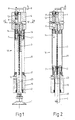
- the individual piston-air cylinder units essentially consist of the cylinder base 10, cylinder tube 11, cylinder head 4, piston 7, piston rod 2 and vacuum suction device 1 (FIGS. 1, 2).
- connection "a" in the cylinder base 10 is pressurized with compressed air and the connection "b" in the cylinder head 4 is depressurized, so that the piston 7 is held in its upper end position (FIGS. 1, 2).
- connection "b" If the connection "b" is now connected to the connection "a", the piston 7 moves downward due to its larger surface area on its upper side, and the vacuum cups 1 rest on the board stack 13. Due to the small difference in the piston areas, the force exerted by the suction cups on the stack is low (FIG. 4).
- the valve piston 6 and the signal pin 8 are moved downward by the compression spring 12, so that the compressed air present at the connection "c" of the cylinder head 4 can flow to the Venturi nozzle 5.
- the Venturi nozzle 5 now sucks air from the vacuum cup 1 via the telescopic tube 3 and the bore 20 in the piston rod 2 (FIG. 3).
- the telescopic tube is sealed off from the central bore by means of a seal 21.
- connection "b" If the connection "b" is now vented again, the piston 7 with the piston rod 2 and the vacuum suction device 1 moves upward, the uppermost board 15 being lifted off the board stack 13 by the negative pressure prevailing in the vacuum suction device 1.
- valve piston 6 Shortly before reaching the upper end position, the valve piston 6 is pushed upwards by the actuating pin 14 against the compression spring 12 and closes the air supply to the Venturi nozzle 5, so that the vacuum in the vacuum suction device 1 is released and the latter is released from the circuit board 15.
- the circuit board is now held by the magnetic tape conveyor 14.
- the signal pin 8 With the valve piston 6, the signal pin 8 is also moved upward, whereby the proximity switches 9 mounted on the cylinder head 4 are damped (FIGS. 4, 5).
- the two elastic buffers 16 and 17 serve to damp the end position of the piston 7 in both end positions.
- the cylinder head 4 is connected to the Venturi nozzle 5 available as a unit via a screw connection 22 and provided with corresponding connection bores 23, 24.
- a flanged connection piece 25 is used for connection as a compressed air supply from connection "c" to the Venturi nozzle 5.
- the screw connections 26, 27 also serve to guide the compressed air to the Venturi nozzle 5.
Landscapes
- Engineering & Computer Science (AREA)
- Mechanical Engineering (AREA)
- Sheets, Magazines, And Separation Thereof (AREA)
Abstract
Description
- Die Erfindung bezieht sich auf eine Einrichtung zum Vereinzeln und Entnehmen von Platinen von einem Platinenstapel nach dem Oberbegriff des Anspruchs 1.
- Zum Vereinzeln, Entnehmen und Weitergeben von Platinen von einem Platinenstapel werden Kolben-Luftzylindereinheiten mit angebauten Vakuumsaugern in verschiedener Art verwendet.
- Hierbei sind alle Vakuumsauger an einer gemeinsamen Hub- und Senkeinrichtung montiert. Dabei ist die Saugeraufhängung so konstruiert, daß die nicht benötigten Vakuumsauger über zusätzliche Kolben-Luftzylindereinheiten zurückgezogen werden können.
- Schwierigkeiten bestanden darin, daß zur Erzeugung des Vakuums im Sauger eine Schlauchleitung parallel zur Kolbenstange verlegt werden mußte oder daß die Einheit mit einer hohlgebohrten, durchgehenden Kolbenstange versehen wurde, an deren hinterem Ende sich der Anschluß für das Vakuum befand. In beiden Fällen muß dabei die Hubbewegung des Saugers durch eine Schlaufe in der Schlauchleitung ausgeglichen werden und die Kolbenstange mußte gegen Verdrehen gesichert werden, was aufwendig ist, viel Platz benötigt und eine Anlage, in der z. T. über dreißig Sauger im Einsatz sind, unübersichtlich macht. Das Zu- und Abschalten der Druckluft zu den einzelnen Venturidüsen erfolgt bei herkömmlichen Anlagen über ein zentrales Elektromagnetventil, wobei immer alle Düsen angesteuert werden, obwohl je nach Platinenform immer nur ein Teil der in der Anlage befindlichen Sauger benötigt werden. Ein weiterer Nachteil ist das große Gewicht der Einrichtung, welches bewegt werden muß.
- Die erfindungsgemäße Einrichtung besteht aus einer Anzahl Kolben-Luftzylindereinheiten auf deren Kolbenstange Vakuumsauger direkt montiert sind. Dabei sind die Kolben-Luftzylinder fest an einem Rahmen angebaut. Die Vakuumversorgung des Saugers erfolgt durch das im Zylinderkopf befestigte und in die Kolbenstange eintauchende Teleskoprohr. Hierdurch wird die gesamte Hubbewegung der Einrichtung nur noch durch die Kolbenstangen mit Vakuumsauger selbst durchgeführt, ohne daß die gesamte Einrichtung bewegt wird. Die sonst notwendigen Schlauchleitungen zu den Saugern bzw. zur Kolben-Zylindereinheit können entfallen.
- In den Unteransprüchen sind weitere vorteilhafte Ausgestaltungen der Erfindung angegeben.
- Dadurch daß der Zylinderkopf ortsfest ist, macht der Vakuumanschluß am Zylinderkopf ebenfalls keine Bewegung und die Venturidüse zur Vakuumerzeugung kann in den Zylinderkopf integriert werden.
- Desweiteren ist im Zylinderkopf ein Ventilkolben vorgesehen, welcher die Druckluftzufuhr zur Venturidüse unterbricht, wenn der Kolben der Kolbenstange in der oberen Endstellung ist. Somit wird ohne weiteren Steuerungsaufwand die Vakuumversorgung für den Vakuumsauger bei der Senk- und Hubbewegung eingeschaltet und kurz vor Erreichen der oberen Endstellung wieder ausgeschaltet. Es werden immer nur die Venturidüsen mit Druckluft beaufschlagt, deren zugeordnete Vakuumsauger im Einsatz sind.
- Der Ventilkolben ist mit einem Signalstift versehen, wodurch die obere Endstellung des Kolbens durch einen handelsüblichen Annäherungsschalter elektrisch abgefragt werden kann.
- Gegenüber einer Kolben-Luftzylindereinheit mit durchgehender Kolbenstange hat die Erfindung den weiteren Vorteil, daß durch die unterschiedlich große Fläche an der Unter- und Oberseite des Kolbens bei gleicher Druckeinstellung für die Hub- und Senkbewegung verschiedene Kolbenkräfte zur Verfügung stehen, d. h. es besteht eine kleine Kraft beim Aufsetzen der Sauger auf den Stapel und eine große Kraft beim Anheben der Platine.
- Die Erfindung wird anhand eines Ausführungsbeispieles näher erläutert.
- Es zeigen:
- Fig. 1 einen Längsschnitt durch eine Kolben-Luftzylindereinheit bei eingefahrener Kolbenstange,
- Fig. 2 dieselbe Einheit bei ausgefahrener Kolbenstange,
- Fig. 3 einen Schnitt nach der Linie A-B der Fig. 1,
- Fig. 4 eine vereinfachte Darstellung der Entstapeleinrichtung beim Aufsetzen der Sauger auf den Platinenstapel und
- Fig. 5 dieselbe Einrichtung nach der Übergabe der Platine an den Magnetbandförderer.
- Die einzelnen Kolben-Luftzylindereinheiten bestehen im wesentlichen aus dem Zylinderboden 10, Zylinderrohr 11, Zylinderkopf 4, Kolben 7, Kolbenstange 2 und Vakuumsauger 1 (Fig. 1, 2).
- In der Ausgangsstellung ist der Anschluß "a" im Zylinderboden 10 mit Druckluft beaufschlagt und der Anschluß "b" im Zylinderkopf 4 ist drucklos, so daß der Kolben 7 in seiner oberen Endstellung gehalten wird (Fig. 1, 2).
- Wird nun der Anschluß "b" mit dem Anschluß "a" verbunden, bewegt sich der Kolben 7, bedingt durch seine größere Fläche an seiner oberen Seite, nach unten und die Vakuumsauger 1 setzen auf den Platinenstapel 13 auf. Durch den geringen Unterschied der Kolbenflächen ist die Kraft, die die Sauger auf den Stapel ausüben gering (Fig. 4).
- Gleichzeitig mit dem Ausfahren des Kolbens wird der Ventilkolben 6 und der Signalstift 8 durch die Druckfeder 12 nach unten bewegt, so daß die am Anschluß "c" des Zylinderkopfes 4 anliegende Druckluft zur Venturidüse 5 strömen kann. Die Venturidüse 5 saugt nun über das Teleskoprohr 3 und die Bohrung 20 in der Kolbenstange 2 Luft aus dem Vakuumsauger 1 (Fig. 3). Das Teleskoprohr ist gegenüber der Zentralbohrung mittels einer Dichtung 21 abgedichtet.
- Wird nun der Anschluß "b" wieder entlüftet, bewegt sich der Kolben 7 mit der Kolbenstange 2 und dem Vakuumsauger 1 nach oben, wobei durch den im Vakuumsauger 1 herrschenden Unterdruck die oberste Platine 15 vom Platinenstapel 13 abgehoben wird.
- Kurz vor Erreichen der oberen Endstellung wird der Ventilkolben 6 durch den Betätigungsstift 14 gegen die Druckfeder 12 nach oben geschoben und verschließt die Luftzufuhr zur Venturidüse 5, so daß sich das Vakuum im Vakuumsauger 1 abbaut und dieser sich von der Platine 15 löst. Die Platine wird nun vom Magnetbandförderer 14 gehalten. Mit dem Ventilkolben 6 wird auch der Signalstift 8 nach oben verschoben, wodurch die am Zylinderkopf 4 angebauten Annäherungsschalter 9 bedämpft werden (Fig. 4, 5).
- Haben alle Kolben der Einrichtung die obere Endlage erreicht (alle Annäherungsschalter sind gedämpft), wird die Platine 15 durch den Magnetbandförderer 14 abtransportiert.
- Zur Endlagendämpfung des Kolbens 7 in beiden Endlagen dienen die beiden elastischen Puffer 16 und 17 (Fig. 1).
- In Fig. 3 ist der Zylinderkopf 4 mit der als Baueinheit lieferbaren Venturidüse 5 über eine Schraubverbindung 22 verbunden und mit entsprechenden Anschlußbohrungen 23, 24 versehen. Ein aufgeflanschtes Verbindungsstück 25 dient zur Verbindung als Druckluftzuführung von Anschluß "c" zur Venturidüse 5. Die Schraubverbindungen 26, 27 dienen gleichzeitig der Druckluftführung zur Venturidüse 5.
Claims (5)
Applications Claiming Priority (2)
| Application Number | Priority Date | Filing Date | Title |
|---|---|---|---|
| DE3936506 | 1989-11-02 | ||
| DE3936506A DE3936506A1 (de) | 1989-11-02 | 1989-11-02 | Vakuumsauger fuer platinenentstapeleinrichtung |
Publications (3)
| Publication Number | Publication Date |
|---|---|
| EP0425960A2 true EP0425960A2 (de) | 1991-05-08 |
| EP0425960A3 EP0425960A3 (en) | 1991-07-31 |
| EP0425960B1 EP0425960B1 (de) | 1994-07-06 |
Family
ID=6392735
Family Applications (1)
| Application Number | Title | Priority Date | Filing Date |
|---|---|---|---|
| EP90120222A Expired - Lifetime EP0425960B1 (de) | 1989-11-02 | 1990-10-22 | Vakuumsauger für Platinenentstapeleinrichtung |
Country Status (2)
| Country | Link |
|---|---|
| EP (1) | EP0425960B1 (de) |
| DE (2) | DE3936506A1 (de) |
Cited By (6)
| Publication number | Priority date | Publication date | Assignee | Title |
|---|---|---|---|---|
| ES2155354A1 (es) * | 1999-10-30 | 2001-05-01 | Marmoles Bempe S L | Perfeccionamientos introducidos en cargadores/descargadores provistos de ventosas de absorcion. |
| US7175176B2 (en) * | 2001-12-10 | 2007-02-13 | Heidelberger Druckmaschinen Ag | Device for feeding suction air or blowing air in a sheet-processing machine |
| EP2019075A2 (de) | 2007-07-24 | 2009-01-28 | J. Schmalz GmbH | Vorrichtung zum Spannen und/oder Halten von Werkstücken |
| CN102471038A (zh) * | 2010-06-03 | 2012-05-23 | 三明公司 | 真空吸附移动装置 |
| US9546050B2 (en) | 2013-01-30 | 2017-01-17 | Lisec Austria Gmbh | Method and device for stacking and unstacking panel-shaped objects |
| CN115924533A (zh) * | 2023-02-21 | 2023-04-07 | 天津金海通半导体设备股份有限公司 | 一种给气伸缩及拾取装置 |
Families Citing this family (5)
| Publication number | Priority date | Publication date | Assignee | Title |
|---|---|---|---|---|
| DE102016203171B3 (de) * | 2016-02-29 | 2017-06-29 | Festo Ag & Co. Kg | Saughaltevorrichtung |
| CN112320331A (zh) * | 2018-10-29 | 2021-02-05 | 浙江厚达智能科技股份有限公司 | 内固定双盘同移式光纤转移机构及光纤转移方法 |
| CN111410038B (zh) * | 2018-10-29 | 2021-07-27 | 浙江厚达智能科技股份有限公司 | 内侧固定式光纤转移装置 |
| CN109367943B (zh) * | 2018-12-03 | 2023-09-01 | 上海金自天正信息技术有限公司 | 一种机器人手持式钢坯贴标装置、系统以及方法 |
| DE202021003145U1 (de) | 2021-10-07 | 2021-11-04 | Dürrschmidt GmbH Handhabungssysteme | Vakuumsauger |
Family Cites Families (9)
| Publication number | Priority date | Publication date | Assignee | Title |
|---|---|---|---|---|
| US3567043A (en) * | 1968-08-05 | 1971-03-02 | Sun Chemical Corp | Transfer assembly for use with container printing machines |
| US3568959A (en) * | 1969-04-09 | 1971-03-09 | Leland F Blaff | Vacuum cup type work gripping means |
| USRE27224E (en) * | 1969-04-16 | 1971-11-09 | Fluid feed lines | |
| US3978991A (en) * | 1973-09-03 | 1976-09-07 | Uwe Kochanneck | Storage installation with automatic pick-up device |
| FR2265659A1 (en) * | 1974-03-29 | 1975-10-24 | Barbe Gaston | Suction-type sheet handling equipment - has valves actuated by pressure difference between housing and compartments |
| DE2526441A1 (de) * | 1975-06-13 | 1976-12-23 | Mey Ohg Geb | Vorrichtung zum abheben einzelner etiketten |
| DE2805377C3 (de) * | 1978-02-09 | 1981-10-22 | Mannesmann AG, 4000 Düsseldorf | Verfahrbare Lastaufnahmevorrichtung |
| JPS62185646A (ja) * | 1986-02-10 | 1987-08-14 | Komatsu Ltd | デイスタツカ |
| DE3644201A1 (de) * | 1986-12-23 | 1988-07-07 | Mabeg Maschinenbau Gmbh Nachf | Pneumatische vorrichtung |
-
1989
- 1989-11-02 DE DE3936506A patent/DE3936506A1/de not_active Withdrawn
-
1990
- 1990-10-22 EP EP90120222A patent/EP0425960B1/de not_active Expired - Lifetime
- 1990-10-22 DE DE59006358T patent/DE59006358D1/de not_active Expired - Fee Related
Cited By (10)
| Publication number | Priority date | Publication date | Assignee | Title |
|---|---|---|---|---|
| ES2155354A1 (es) * | 1999-10-30 | 2001-05-01 | Marmoles Bempe S L | Perfeccionamientos introducidos en cargadores/descargadores provistos de ventosas de absorcion. |
| US7175176B2 (en) * | 2001-12-10 | 2007-02-13 | Heidelberger Druckmaschinen Ag | Device for feeding suction air or blowing air in a sheet-processing machine |
| EP2019075A2 (de) | 2007-07-24 | 2009-01-28 | J. Schmalz GmbH | Vorrichtung zum Spannen und/oder Halten von Werkstücken |
| EP2019075A3 (de) * | 2007-07-24 | 2009-02-18 | J. Schmalz GmbH | Vorrichtung zum Spannen und/oder Halten von Werkstücken |
| DE202008018192U1 (de) | 2007-07-24 | 2011-12-13 | J. Schmalz Gmbh | Vorrichtung zum Spannen und/oder Halten von Werkstücken |
| CN102471038A (zh) * | 2010-06-03 | 2012-05-23 | 三明公司 | 真空吸附移动装置 |
| CN102471038B (zh) * | 2010-06-03 | 2014-06-25 | 三明公司 | 真空吸附移动装置 |
| US9546050B2 (en) | 2013-01-30 | 2017-01-17 | Lisec Austria Gmbh | Method and device for stacking and unstacking panel-shaped objects |
| RU2611851C2 (ru) * | 2013-01-30 | 2017-03-01 | Лисец Аустриа Гмбх | Устройство для укладывания в стопу и извлечения из стопы пластинообразных объектов |
| CN115924533A (zh) * | 2023-02-21 | 2023-04-07 | 天津金海通半导体设备股份有限公司 | 一种给气伸缩及拾取装置 |
Also Published As
| Publication number | Publication date |
|---|---|
| DE3936506A1 (de) | 1991-05-08 |
| DE59006358D1 (de) | 1994-08-11 |
| EP0425960A3 (en) | 1991-07-31 |
| EP0425960B1 (de) | 1994-07-06 |
Similar Documents
| Publication | Publication Date | Title |
|---|---|---|
| EP0284806B1 (de) | Saugkopf mit Hubsaugern | |
| EP0425960B1 (de) | Vakuumsauger für Platinenentstapeleinrichtung | |
| EP0173755A1 (de) | Zieheinrichtung in einer Presse | |
| DE19732243C2 (de) | Palettiervorrichtung | |
| DE2253755C3 (de) | Vorrichtung zum automatischen horizontalen Ausrichten eines Trägerfahrzeugs für einen Kran o.dgl | |
| DE1785373A1 (de) | Vorrichtung zum Abheben einzelner Gewebestuecke von einem Stapel und zum Auslegen derselben in einer bestimmten Lage | |
| DE4427488A1 (de) | Verfahren zum Palettieren von Stückgutteilen und Stückgutgreifer insbesondere für Roboter, insbesondere zur Paketpalettierung | |
| DE2802475C3 (de) | Saugluftsteuerung für Bogenanlegemaschinen | |
| EP0315161A2 (de) | Vorrichtung zur Bestückung insbesondere von Leiterplatten | |
| DE4339839A1 (de) | Abstapelvorrichtung für Bleche | |
| DE1255115B (de) | Vorrichtung zum Vereinzeln des jeweils obersten flachen, biegsamen und horizontal liegenden Gegenstandes eines Stapels solcher Gegenstaende | |
| DE2710448C2 (de) | Pneumatische Vorrichtung zum Vereinzeln des obersten Bogens eines Bogenstapels | |
| DE2218682A1 (de) | Vorrichtung zum Entstapeln von Blechfolien und/oder Blechtafeln | |
| DD278566A1 (de) | Vorrichtung zum vereinzeln und foerdern von gestapelten bogen | |
| DE2947922A1 (de) | Stapelhebevorrichtung | |
| DE2606075A1 (de) | Vereinzelungsvorrichtung fuer ineinandergesteckte eimer mit tragbuegeln und verfahren zum vereinzeln ineinandergesteckter eimer | |
| DE3902663A1 (de) | Hubsauger fuer eine transporteinrichtung | |
| DE2313598A1 (de) | Vorrichtung zum abheben, transportieren und absetzen von plattenartigen werkstuecken zum anbau an stapel- und beschickungsgeraete | |
| DE2250678A1 (de) | Verfahren zum mechanischen aufstecken von saecken, insbesondere von ventilbodensaecken auf den stutzen von fuellmaschinen und maschine zur durchfuehrung des verfahrens | |
| DE8801727U1 (de) | Spritzgestänge | |
| DE102006021167B4 (de) | Automatischer Anleger für Gegenstände, wie Druckerzeugnisse oder Warenmuster | |
| DE3102321C2 (de) | ||
| DE3519848C2 (de) | Dampfbügelstation | |
| DE437179C (de) | Austragvorrichtung fuer Ziehpressen u. dgl., insbesondere zur Herstellung von Schachtelteilen | |
| DE3119797A1 (de) | "poekelspritzmaschine" |
Legal Events
| Date | Code | Title | Description |
|---|---|---|---|
| PUAI | Public reference made under article 153(3) epc to a published international application that has entered the european phase |
Free format text: ORIGINAL CODE: 0009012 |
|
| AK | Designated contracting states |
Kind code of ref document: A2 Designated state(s): DE FR IT SE |
|
| PUAL | Search report despatched |
Free format text: ORIGINAL CODE: 0009013 |
|
| AK | Designated contracting states |
Kind code of ref document: A3 Designated state(s): DE FR IT SE |
|
| 17P | Request for examination filed |
Effective date: 19911004 |
|
| 17Q | First examination report despatched |
Effective date: 19930421 |
|
| GRAA | (expected) grant |
Free format text: ORIGINAL CODE: 0009210 |
|
| AK | Designated contracting states |
Kind code of ref document: B1 Designated state(s): DE FR IT SE |
|
| REF | Corresponds to: |
Ref document number: 59006358 Country of ref document: DE Date of ref document: 19940811 |
|
| ET | Fr: translation filed | ||
| ITF | It: translation for a ep patent filed | ||
| PG25 | Lapsed in a contracting state [announced via postgrant information from national office to epo] |
Ref country code: SE Effective date: 19941006 |
|
| PLBE | No opposition filed within time limit |
Free format text: ORIGINAL CODE: 0009261 |
|
| STAA | Information on the status of an ep patent application or granted ep patent |
Free format text: STATUS: NO OPPOSITION FILED WITHIN TIME LIMIT |
|
| 26N | No opposition filed | ||
| PGFP | Annual fee paid to national office [announced via postgrant information from national office to epo] |
Ref country code: DE Payment date: 20021004 Year of fee payment: 13 |
|
| PGFP | Annual fee paid to national office [announced via postgrant information from national office to epo] |
Ref country code: FR Payment date: 20021018 Year of fee payment: 13 |
|
| PG25 | Lapsed in a contracting state [announced via postgrant information from national office to epo] |
Ref country code: DE Free format text: LAPSE BECAUSE OF NON-PAYMENT OF DUE FEES Effective date: 20040501 |
|
| PG25 | Lapsed in a contracting state [announced via postgrant information from national office to epo] |
Ref country code: FR Free format text: LAPSE BECAUSE OF NON-PAYMENT OF DUE FEES Effective date: 20040630 |
|
| REG | Reference to a national code |
Ref country code: FR Ref legal event code: ST |
|
| PG25 | Lapsed in a contracting state [announced via postgrant information from national office to epo] |
Ref country code: IT Free format text: LAPSE BECAUSE OF NON-PAYMENT OF DUE FEES;WARNING: LAPSES OF ITALIAN PATENTS WITH EFFECTIVE DATE BEFORE 2007 MAY HAVE OCCURRED AT ANY TIME BEFORE 2007. THE CORRECT EFFECTIVE DATE MAY BE DIFFERENT FROM THE ONE RECORDED. Effective date: 20051022 |