EP0425994B1 - Méthode et machine à tronçonner des tubes et à chamfreiner les extrémités ainsi obtenues - Google Patents
Méthode et machine à tronçonner des tubes et à chamfreiner les extrémités ainsi obtenues Download PDFInfo
- Publication number
- EP0425994B1 EP0425994B1 EP90120385A EP90120385A EP0425994B1 EP 0425994 B1 EP0425994 B1 EP 0425994B1 EP 90120385 A EP90120385 A EP 90120385A EP 90120385 A EP90120385 A EP 90120385A EP 0425994 B1 EP0425994 B1 EP 0425994B1
- Authority
- EP
- European Patent Office
- Prior art keywords
- chamfering
- piston
- machine
- accordance
- pipe
- Prior art date
- Legal status (The legal status is an assumption and is not a legal conclusion. Google has not performed a legal analysis and makes no representation as to the accuracy of the status listed.)
- Expired - Lifetime
Links
Images






Classifications
-
- B—PERFORMING OPERATIONS; TRANSPORTING
- B23—MACHINE TOOLS; METAL-WORKING NOT OTHERWISE PROVIDED FOR
- B23B—TURNING; BORING
- B23B5/00—Turning-machines or devices specially adapted for particular work; Accessories specially adapted therefor
- B23B5/14—Cutting-off lathes
-
- B—PERFORMING OPERATIONS; TRANSPORTING
- B23—MACHINE TOOLS; METAL-WORKING NOT OTHERWISE PROVIDED FOR
- B23B—TURNING; BORING
- B23B5/00—Turning-machines or devices specially adapted for particular work; Accessories specially adapted therefor
- B23B5/16—Turning-machines or devices specially adapted for particular work; Accessories specially adapted therefor for bevelling, chamfering, or deburring the ends of bars or tubes
-
- B—PERFORMING OPERATIONS; TRANSPORTING
- B23—MACHINE TOOLS; METAL-WORKING NOT OTHERWISE PROVIDED FOR
- B23Q—DETAILS, COMPONENTS, OR ACCESSORIES FOR MACHINE TOOLS, e.g. ARRANGEMENTS FOR COPYING OR CONTROLLING; MACHINE TOOLS IN GENERAL CHARACTERISED BY THE CONSTRUCTION OF PARTICULAR DETAILS OR COMPONENTS; COMBINATIONS OR ASSOCIATIONS OF METAL-WORKING MACHINES, NOT DIRECTED TO A PARTICULAR RESULT
- B23Q7/00—Arrangements for handling work specially combined with or arranged in, or specially adapted for use in connection with, machine tools, e.g. for conveying, loading, positioning, discharging, sorting
- B23Q7/04—Arrangements for handling work specially combined with or arranged in, or specially adapted for use in connection with, machine tools, e.g. for conveying, loading, positioning, discharging, sorting by means of grippers
- B23Q7/043—Construction of the grippers
-
- B—PERFORMING OPERATIONS; TRANSPORTING
- B25—HAND TOOLS; PORTABLE POWER-DRIVEN TOOLS; MANIPULATORS
- B25B—TOOLS OR BENCH DEVICES NOT OTHERWISE PROVIDED FOR, FOR FASTENING, CONNECTING, DISENGAGING, OR HOLDING
- B25B5/00—Clamps
- B25B5/14—Clamps for work of special profile
- B25B5/147—Clamps for work of special profile for pipes
Definitions
- the invention relates to a machine for parting pipes and chamfering the pipe end edges formed here with a parting head for clamping a pipe end from an axially displaceable by means of an annular hydraulic piston-cylinder unit pressure sleeve with radial wedge surfaces and concentrically arranged, axially immovable, by means of complementary Wedge surfaces of radially adjustable clamping jaws, with a rotatable face plate coupled with a rotary drive for receiving at least two radially opposite and radially adjustable parting tools and chamfering tools and with a gripper for holding the pipe part to be cut off from clamping jaws which can be actuated by means of a hydraulic piston-cylinder unit, as well as a Method for parting and chamfering pipes according to the preamble of claim 15.
- the face plate can be axially displaced by means of a plurality of hydraulic piston-cylinder units fixed to the housing and arranged concentrically around the axis of the pressure sleeve, the piston rods of the hydraulic piston-cylinder units bearing two longitudinally adjustable and lockable stop rings, the spacing of which increases an end wall of the cylinder and a wall of the housing is changeable.
- the drive of the radially adjustable parting-off tools and / or possibly chamfering tools is not described in detail in DE-OS 36 12 960.
- the parting and chamfering is carried out by moving a combined parting and chamfering tool in a planetary, radially circular manner towards the tube, piercing a groove in the tube until the tube is completely divided, after which the chamfering area of the tool is countered moves the outer edges and attaches the chamfers.
- the pipe ends are moved apart, the chamfering tool is moved into the inside of the pipe and the chamfers on the left pipe end and on the right pipe end are produced one after the other by opposite axial movements of the chamfering tool.
- the chamfering tool is then moved radially outwards from the inside of the pipe.
- the invention has for its object to improve a method and a machine of the type mentioned in such a way that an exact axial displacement of the face plate in three defined positions can be achieved without the risk of tilting.
- part of the task is to create a rotary drive for the radial infeed of the parting tools and, if necessary, chamfering tools, which can be used independently of the Diameter of the pipe to be cut off can be delicately and precisely cut off and / or chamfered.
- a wiper is also to be created, with which a pipe end can be clamped in a manner that is centric with respect to a parting-off head, regardless of the pipe diameter.
- the scraper should be able to be adapted easily and with little effort to different pipe diameters and pipe wall thicknesses and should be controllable in such a way that a pipe end can be pushed through or a short, cut piece of pipe can fall out downwards.
- the face plate according to the invention by means of an annular hydraulic piston-cylinder unit consisting of an annular piston fixed to the housing, a sliding bushing rotatably supporting the face plate and an axially movable stop concentrically and axially displaceable on one
- the housing-fixed bushing of the hydraulic piston-cylinder unit for the parting head is arranged and the rotary drive of the face plate carries independent rotary drives arranged concentrically to one another for the radial infeed of the parting tools and chamfering tools.
- the ring-shaped hydraulic piston-cylinder unit always engages centrally, so that tilting is not possible when actuated.
- the independent rotary drive for the radial infeed of the parting-off tools and possibly chamfering tools can be easily integrated into the machine with the rotary drive for the face plate in such a way that the radial infeed movement is derived directly from the rotary movement of the independent rotary drive without being influenced by the Rotary drive for the face plate is given.
- the radial guides can consist of needle-bearing prism guide strips which are arranged in radial recesses of the face plate, which in turn are spanned by pull tabs.
- the radial recesses can be open on one side without being able to bend open, since this bend is prevented by the pull tabs.
- clamping screws arranged axially parallel to the axis of rotation of the face plate can engage in bores at the ends of the pull tab heads, the conical heads of which engage until there is no play on the Drilled holes in the ends of the pull tabs.
- the rotary drive for the face plate can preferably have a pinion mounted in the housing, which meshes with a gear on the face plate and has an internal toothing that engages with a sun gear fixed to the housing via planet gears mounted in a rotatable cage, while the rotary drive for the radial one Delivery of the parting-off tools and, if applicable, chamfering tools can have a pinion with internal toothing, which is mounted in the housing and engages with a gear wheel rotatably mounted on the face plate, and which meshes with a rotatable sun gear via planet gears mounted in the same cage, the rotatable sun gear from one Servomotor can be driven in both directions and is kept braked at a standstill.
- the pinions have the same peripheral speed as long as both sun gears stand still, since the planet gears roll with the cages on the sun gears. If the rotatable sun gear is driven by the servo motor in one direction or the other, there is a relative rotation of the drive pinion for the face plate with reference to the drive pinion for the radial infeed of the parting-off tools and possibly chamfering tools, so that the threaded spindle drive in via the corresponding crown gears and bevel pinions Offset and thus the radial infeed is effected.
- the servo motor can preferably consist of a three-phase motor with an incremental encoder arranged thereon. In this way, the angular position of the servo motor can be precisely checked and controlled.
- An angle-precise drive connection between the servo motor and the rotatable sun gear can advantageously be achieved via a toothed belt drive.
- a crown gear can be connected to a drive gear wheel, which is rotatably mounted on the face plate, for the radial infeed of the parting-off tools and, if applicable, chamfering tools can be delivered radially by an independent rotary drive via a pinion with internal teeth, planet gears and a sun gear.
- a particularly simple construction of the ring-shaped hydraulic piston-cylinder unit for the axial adjustment of the face plate can be achieved with a ring piston fixed to the housing and a sliding bushing that rotatably supports the face plate.
- a movable, hydraulically controlled ring piston can be arranged as an adjustable stop for the sliding bush between the ring piston fixed to the housing and the sliding bush.
- the axial adjustment of the face plate with three defined positions can advantageously be achieved in that the front and rear of the annular piston fixed to the housing is controlled via outputs A, B of a 4/3-way valve, that the front of the movable annular piston with the cylinder space of the rear of the is connected to the housing-fixed ring piston and that the rear of the movable ring piston is controlled via the output (B) of a 4/2-way valve while the output (A) is blocked.
- This control has the effect that the path of the movable ring piston forward is limited by a stop on the ring piston fixed to the housing and by a stop on the sliding bushing, and the path backwards is limited by a stop on the sliding bushing and that the path of the sliding bushing is in contact with the movable ring piston the sliding bushing is limited to a central position by acting on the rear of the movable ring piston.
- the method according to the invention is characterized in that a parting tool separated from the chamfering tool is used, both of which move radially inwards at the same time or essentially simultaneously at different speeds, the parting off process only being completed after the outer bevels have been completed, as is known, and in that the manufacture of the Only one of the two pipe ends is moved axially, after which the chamfering tool is inserted into the gap and is first brought into the cutting position in the direction of the non-axially moving pipe end without cutting feed, and then the axially moving pipe end is moved back to the cutting position on the chamfering tool. after which the chamfering tool for producing the inner bevels is moved radially outwards and finally one end of the pipe is moved axially away from the other again in order to lead out the chamfering tool.
- the parting-off tool can preferably remain in its initial position during the course of the production of the inner chamfers.
- the pipe ends or the chamfering tool need only be moved axially in rapid traverse and are fixed in their end positions by stops, so that no feed to be controlled with great accuracy is required. Furthermore, the outer bevels are attached before the pipe end is completely tapped, at the same time on opposite end edges of the pipe ends, which has a favorable effect on the accuracy. No specially designed shaped steel is required to produce the inner and outer chamfers, since the chamfer edges alone determine the angle of the chamfer, while the chamfer width is determined by the advance of the chamfering tool.
- a gripper for holding a pipe part to be cut off and for axially displacing a pierced pipe part can be designed such that a hydraulic piston-cylinder unit of the claw is arranged on a housing and carries an upper clamping jaw and a clamping wedge on its piston rod that two more Clamping jaws are arranged on two double-armed levers pivoted in the housing, and the double-armed levers interact with the clamping part.
- the profile of the clamping wedge is preferably designed so that it causes a movement of the clamping jaws which is always directed towards the same center over the entire stroke of the piston rod.
- This center point is coaxially aligned with the center point of the parting head, and the three jaws of the pickup are also aligned with the jaws of the parting head, so that a pipe clamped by the picker and the parting head is clamped without shear force, regardless of whether this pipe has a certain ovality or wall thickness differences. This means that there is no jumping and jamming during the puncture.
- the upper clamping jaws at the end of the piston rod can be flat and the clamping jaws on the double-armed levers can be cylindrical. In this way, a line contact is achieved on the pipe surface, which is evenly distributed on the pipe circumference and takes into account the fact that the piston rod moves in a straight line, but the clamping jaws on the double-armed levers move on an arc.
- all three clamping jaws can be arranged so that they can pivot and have a gripping profile corresponding to the pipe diameter. If this gripping profile is designed as a circular arc with the same diameter as the pipe to be clamped, there will be surface contact between the clamping jaws and the pipe to be clamped instead, which ensures gentle clamping of the pipe.
- a displacement sensor can be connected to the piston rod Hydraulic piston-cylinder unit of the wiper controls accordingly.
- the double-acting hydraulic piston-cylinder unit can form the end of the chain and the middle, single-acting hydraulic piston-cylinder unit can have a return spring and a piston rod that plunges into the cylinder of the double-acting hydraulic piston-cylinder unit.
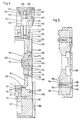
- the main flange 3 has an indentation 6, into which a cylindrical main bushing 7 is inserted and held non-rotatably and immovably by means of fastening screws 8.
- the main bushing 7 has a radially projecting collar 15, which forms a double-acting ring piston with a high-pressure seal 16.
- An inner bore 9 in the main bush 7 goes via a shoulder 10 into an inner bore 11 of smaller diameter about.
- a high-pressure seal 13 is arranged in the area of the shoulder 10.
- the bore 11 ends in a further shoulder 12, from which an obliquely arranged ventilation bore 14 leads into an end region of the main bushing 7.
- a further high-pressure seal 17 is arranged in this end region.
- a clamping nut 18 is screwed into the front end of the main bushing 7 by means of a thread 40.
- a stop flange 19 is fastened in a recess 21 of the cylindrical extension 4 by means of fastening screws 20.
- the stop flange 19 engages with a cylindrical extension 135 in the bore 9 of the main bushing 7 and is sealed there by means of an O-ring seal 22.
- a tensioning piston 25 is guided in the cylindrical extension 135 by means of a slide ring 27 and sealed against it by means of a high-pressure seal 26.
- a collar 28 on the tensioning piston 25 forms an annular piston which is guided in a sealed manner in the bore 9 of the main bushing 7 by means of a high-pressure seal 29.
- the annular piston 28 has a piston side 30 causing tensioning and a piston side 31 causing release.
- the piston side 30 is directed towards a cylinder space 32 and the piston side 31 towards a cylinder space 33.
- the effective area of the piston side 30 causing the tensioning is larger than that of the piston side 31 causing the release.
- a radial pressure oil supply and discharge line 34 is arranged in the area of the cylinder space 32, while a further radial pressure oil supply and discharge line 35 is arranged in the area of the cylinder space 33. Both lines 34, 35 are connected to separate axial lines, not shown, which are guided through the main bushing 7, the main flange 3 and the cylindrical extension 4, as is shown with respect to an axial bore 85.
- the front end of the tensioning piston 25 is screwed by means of a thread 112 to a pressure sleeve 36, which extends axially into the area of the tensioning nut 18 and is guided there by means of a slide ring 39.
- a feather key 41 fastened to the pressure sleeve 36 by means of a fastening screw 42 allows an axial displacement in a keyway 43 to, but at the same time secures the pressure sleeve 36 and the tensioning piston 25 against rotation relative to the main bushing 7.
- the pressure sleeve 36 has three rear wedge surfaces 37 and front wedge surfaces 38 evenly distributed over the circumference, which interact with corresponding, complementary rear wedge surfaces 45 and front wedge surfaces 46 on three clamping jaws 44. Between the front wedge surface 46 and the rear wedge surface 45 of the clamping jaw 44 there is a free space 47 which determines the axial distance between the rear wedge surface 45 and the front wedge surface 46. In the area of the front wedge surface 46 of each clamping jaw 44, an exchangeable clamping block 48 is fastened by means of a fastening screw 49. These clamping blocks 48 are available in different radial dimensions and are used to adapt the parting head to different pipe diameters.
- curved spreading spring leaves 50 are arranged, which are supported on the clamping jaws 44 and press them radially outwards. These spreading spring leaves 50 serve as return springs for the clamping jaws 44 if they are to be released by retracting the clamping piston 25 and the pressure sleeve 36.
- the clamping jaws 44 are arranged with little axial play between the clamping nut 18 and the end flange 23 and are supported during clamping with their end face on the clamping nut 18 and when loosening by means of a rear flange 119 on the end flange 23.
- a lubricating oil bore 52 leads from the rear end face of the stop flange 19 to a front region of the main bushing 7 and from there radially outward, in order to ensure the lubricating oil supply of shoulder ball bearings 76, 77 arranged on a sliding bushing 53 via lubricating oil bores 60.
- the sliding bush 53 has a shoulder 54 which delimits a cylinder space 57 to the front. Another shoulder 55 in the sliding bush 53 delimits a cylinder chamber 59 for the annular piston 15 fixed to the housing.
- a high-pressure seal 56 seals a cylinder chamber 58 against an annular piston 71, which is guided with its inner bore on the cylindrical main bush 7 and sealed by means of a high-pressure seal 72 is.
- An O-ring seal 61 and a further, axially offset O-ring seal 62 serve to seal the lubricating oil bores 52, 60 from the outside.
- a flange 63 is screwed to the sliding bush 53 by means of fastening screws 64 and is sealed off from it by means of an O-ring seal 65.
- a high-pressure seal 66 is arranged in the flange 63 and takes over the sealing against the main bushing 7.
- a slide ring 67 takes over the guidance of the main bushing 7 in the flange 63.
- a clamping ring 68 is screwed by means of fastening screws 69, and a sliding ring 70 takes over the guidance of the front end of the sliding bush 53 on the main bushing 7.
- the shoulder ball bearings 76, 77 are opened by means of the flange 63 and the clamping ring 68 the sliding bush 53 axially fixed and held.
- the ring piston 71 has a front side 73 which can move up to a stop 75 on the ring piston 15 fixed to the housing. Furthermore, the annular piston 71 has a rear side 74, the movement of which is limited by a stop 136 on the flange 63.
- a drive bushing 78 is rotatably mounted on the sliding bushing 53 by means of the shoulder ball bearings 76, 77. This drive bushing 78 is provided at its rear end with a ring gear 79 in which a rotary drive, not shown, engages.
- a radial seal 80 seals the front end of the drive bush 78 against the clamping ring 68.
- An axial lubricating oil bore 81 in the drive bushing 78 returns lubricating oil from the area between the shoulder ball bearing 76 and the radial seal 80 into the space between the two shoulder ball bearings 76, 77.
- a drive plate 78 is connected to a face plate 82 shown in FIGS. 3 to 5, which carries not shown radially opposite and radially adjustable parting tools and / or possibly chamfering tools.
- the face plate 82 is fastened to the drive bushing 78 by means of fastening screws 83.
- At least one radial bore 84 is arranged in the annular piston 71, which connects a radial bore 86 in the main bushing 7 to the cylinder space 57.
- the radial bore 86 is guided via the axial bore 85 to the end face of the stop flange 19 and is connected there to a pressure medium line.
- Corresponding radial bores 87 and 88 lead to the cylinder spaces 58 and 59 and are also offset from the axial bore 85 to the stop flange 19 and connected there in a manner not shown with a pressure medium line.
- a central control ring 89 with a ring gear 90 which is fastened to the central control ring 89 by means of fastening screws 91, is rotatably mounted on the drive bushing 78 via two shoulder ball bearings 92, 93.
- the axial preload of the shoulder ball bearings 92, 93 is set by means of a spacer ring 94, which bears against a collar 97 of the face plate 82.
- Radial sealing rings 95, 96 provide a seal for the central control ring 89 and its ring gear 90 with respect to the drive bushing 78.
- the fitting ring 100 serves to set the tooth flank play of the small crown gear 98 in relation to a small bevel pinion 109 in the face plate 82.
- a front control ring 101 with a ring gear 102 is rotatably mounted via two further shoulder ball bearings 137, 138.
- a large crown gear 103 is fastened to the front control ring 101 by means of fastening screws 104 and with the interposition of a further fitting ring 105.
- the large crown gear 103 is in engagement with a large bevel pinion 108 in the face plate 82.
- Radial sealing rings 106, 107 provide a seal for the front control ring 101 with respect to the central control ring 89.
- the ring gears 90, 102 are in engagement with one in FIG. 2 Drive device shown, which allows these sprockets to rotate independently of each other relative to the ring gear 79.
- This rotation is transmitted via the small crown gear 98 or the large crown gear 103 to the small bevel pinion 109 or the large bevel pinion 108, which set a threaded spindle 110 in rotation.
- the rotation of the threaded spindle 110 brings about a radial displacement of parting-off tools and / or possibly chamfering tools (not shown) and thus the machining of a pipe end clamped in the parting-off head.
- three further bores 113 are arranged, which serve to receive the rotary drive for the face plate 82 and the rotary drives for the radial feed of the parting and chamfering tools.
- a Receiving flange 114 fitted into the bore 113 with a cylindrical projection 115 and fastened by means of fastening screws 116.
- the inside of the housing is sealed by an O-ring seal 117.
- a central bore 118 is arranged in the receiving flange 114 and serves to receive a hollow shaft 119.
- the hollow shaft 119 has a cylindrical projection 120, so that a shoulder 121 is formed, which is based on the inside of the receiving flange 114.
- the hollow shaft 119 is fastened to the receiving flange 114 with fastening screws 122 and sealed with respect to the latter by means of an O-ring seal 123.
- the hollow shaft 119 has a toothing 124 which forms a fixed sun gear for a planetary gear described below.
- Axial lubricating oil bores 126 and a radial lubricating oil bore 125 are guided through the housing 1 and the receiving flange 114 and merge into an axial lubricating oil bore 127 in the hollow shaft 119 and a radial lubricating oil bore 128.
- Lubricating oil is guided to tapered roller bearings 159, 160 via these bores 125, 126, 127, 128.
- a drive shaft 129 is rotatably mounted in the hollow shaft 119.
- a rotatable sun gear 130 is arranged at one end of the drive shaft 129, while the other end of the drive shaft 129 is guided outward through the receiving flange 114 and carries a toothed belt wheel 131.
- the drive shaft 129 is supported in a needle bearing 132, which is supported on the hollow shaft 119.
- a radial sealing ring 133 ensures the seal to the outside.
- a double-row angular contact ball bearing 134 is arranged, which carries a cage formed in the planetary gear from a part 180 and a part 181, which are connected by means of screws 182.
- This cage 180, 181 is supported by a tapered roller bearing 183 in the receiving flange 114 and by a tapered roller bearing 184 in a flange 141 on a receiving pin 140.
- the receiving pin 140 is tensioned in a corresponding bore in the housing 1 by means of ring springs 143, a spacer bush 144, a cover plate 146 and a clamping screw 145 after the axial play of the tapered roller bearings 183, 184 by means of one supporting the housing 1 Adjusting nut 142 was set.
- the end plate 146 is sealed to the outside by means of an O-ring seal 147.
- a flange 149 of a lubricating nozzle 148 is inserted into the flange-side end of the receiving pin 140 and screwed by means of fastening screws 150.
- Lubricating oil bores 151, 152, 153, 154 lead from the lubricating nozzle 148 to a lubricating oil connection, from which lubricating oil is supplied to the double-row angular contact ball bearing 134, the tapered roller bearing 184 and two further tapered roller bearings 164, 165.
- a gear 156 is rotatably supported by means of tapered roller bearings 159, 160.
- the gear 156 carries an external toothing 157 and an internal toothing 158.
- Another gear 161 with external teeth 162 and internal teeth 163 is supported by two tapered roller bearings 164, 165 at the other end of the cage 180, 181.
- the toothings 162, 162a are axially offset drawn, but are part of two different planetary gears, one of which has a gear 161 with the teeth 162 and the other has a gear 161 with the teeth 162a.
- Bolts 166 are regularly arranged in a circle in the cage 180, 181, wherein in each case one bolt 166 axially offset carries a planet gear 167 and a planet gear 168.
- the planet gears 167, 168 have the same diameter and are mounted on the bolts 166 by means of radial needle bearings 169, 170 and secured against axial displacement by axial needle bearings 171, 172, 173.
- a thrust washer 174 is disposed between the gears 167 and 168.
- a three-phase servo motor 175 is screwed to the housing 1 by means of a bracket 178 and by means of fastening screws 179 and carries a toothed belt wheel 176, from which there is a drive connection via a toothed belt 177 to the toothed belt wheel 131.
- the ring gear 79 also drives the gears 156 of the two planetary gears.
- the planet gears 167 are set in rotation via the internal toothing 158 and roll on the fixed sun gear 124.
- the planet gears 167 take the bolt 166 and the cage 180, 181 with them.
- the planet gears 168 are also carried along by the bolt 166 and the housing 180, 181, roll on the stationary sun gear 130 and impart the same speed of rotation to the internal toothing 163 and thus to the gear 161 as it receives the gear 156 through the drive bushing 78. There is therefore no relative rotation of the gear 156 relative to the gear wheels 161, so that the ring gear 90 or the ring gear 102 likewise does not rotate relative to the ring gear 79.
- the small crown gear 98 and the large crown gear 103 rotate at the same speed as the face plate 82, so that there is no rotation of the small or large bevel pinion 108, 109 and therefore no movement of the parting and chamfering tools takes place in the radial direction.
- gear 161 rotates faster or slower than gear 156 depending on the direction of rotation of three-phase servo motor 175 and gives gear ring 90 or gear ring 102 a relative rotation with respect to gear ring 79, so that small crown gear 98 or large crown gear 103 rotates relative to the face plate Turn 82, set the small bevel pinion 109 or the large bevel pinion 108 in rotation and thus bring about a radial movement of the parting-off or chamfering tools.
- the face plate 82 with the spindle drive for the parting and chamfering tools is shown in detail in FIGS. 3 to 5.
- the actual face plate 82 is surrounded by a drum 185. With the outer circumference, the drum 185 is fitted into a corresponding housing opening of the housing 1 with little play.
- An annular recess 186 is arranged on the rear side of the face plate 82 and is connected to four radial recesses 187 arranged at an angle of 90 ° to one another.
- the radial recesses 187 are widened to the front of the face plate 82 and serve to accommodate parallel prism guide strips 188 which are screwed onto the face plate 82 by means of fastening screws 190.
- a cylindrical slide 211 is guided in the prism guide strips 188 by means of needle guides 214.
- the play of the needle guides 214 can be adjusted by means of the screws 191 by means of a wedge-shaped adjusting strip 189.
- Each radial recess 187 is overlapped by a pull tab 192 which serves to prevent the radial recesses 187 from gaping apart under the action of the centrifugal forces and the forces in the prism guide strips 188.
- clamping blocks 193 are arranged in the face plate 82 in corresponding bores, which are screwed to the face plate 82 by means of fastening screws 194.
- Tensioning screws 195 with a cylindrical shaft 196 and a conical head 197 can be screwed into the clamping blocks 193 until the conical heads 197 come to bear tightly on corresponding bores in the ends of the pull tabs 192.
- the transverse force exerted by the pull tab 192 on the clamping screws 195 is transmitted to the face plate 82 through the cylindrical shaft 196 which is closely fitted in the bore of the clamping block 193.
- the heads 197 of the clamping screws 195 are covered by a cover screw 198.
- Each radial recess 187 is closed by a bearing segment 199, which is fastened by means of fastening screws 200 and is encompassed by the drum 185.
- a bearing flange 201 is screwed against the bearing segment 199 by means of fastening screws 204.
- the bearing flange 201 serves as a bearing ring for a radial needle bearing 205.
- the inner ring for this radial needle bearing 205 is supported by a bearing nut 202 formed, which is screwed onto the outer end of the threaded spindle 110 and secured against loosening.
- An axial needle bearing 206 is arranged between the bearing flange 201 and the bearing nut 202.
- a corresponding axial needle bearing 206 is arranged on the other side of the bearing flange 201 and interacts with a bearing ring 203.
- the large bevel pinion 108 or the small bevel pinion 109 are non-rotatably connected to the threaded spindle 110 and are supported on the bearing flange 201 via the radial needle bearing 205 and the axial needle bearing 206.
- a shim 207 is used to set the backlash between the large bevel pinion 108 and the large crown gear 103 or the small bevel pinion 109 and the small crown gear 98.
- the threaded spindle 110 interacts with a spindle nut 208 which is connected to a receiving piece 209 by means of fastening screws 210.
- This receiving piece 209 is screwed to the slide 211 by means of fastening screws 213 and gives it a radial movement corresponding to the rotation of the threaded spindle 110.
- Each carriage 211 has a recess 212 in which the parting or chamfering tools are fastened.
- the slides 211 are thus given a precisely controlled radial movement via the three-phase servo motors 175 and the incremental encoders connected to them, which ensures quick, clean, precise machining of the pipe ends.
- a cover plate 215 overlaps the fastening screws 213 of the slide 211. Furthermore, an annular protective plate 216 is arranged on the front of the face plate 82 and fastened by means of fastening screws 217. This mudguard covers the inner area of the front of the face plate 82. A radial sealing ring 218 ensures the sealing of the face plate 82 with respect to the clamping nut 18.
- Each slide 211 is assigned a wiper 219, which is held between a chip guard 220 and a sealing plate 222 by means of fastening screws 221.
- the sealing plate 222 is fastened to the face plate 82 by means of fastening screws 223.
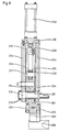
- Another one Fender 224 is arranged in front of the drum 185 and covers the gap to the face plate 82. 6 shows the actuation of the axial displacement of the face plate 82.
- the face plate 82 is rotatably but axially immovable on the sliding bush 53.
- the main bushing 7 carries the sliding bushing 53.
- the cylinder space 57 in the sliding bushing 53 is pressurized or relieved of pressure via a radial bore 86 and an axial bore 85 in the main bushing 7.
- the cylinder space 58 is connected to the outside via a radial bore 87 and an axial bore 225, while this connection to the cylinder space 49 is ensured via the radial bore 88 and an axial bore 226.
- the pressurization or pressure relief of the axial bores 225, 226 takes place via a pressure reducing valve 230, a 4/3-way valve 227 and a twin throttle check valve 228, while the pressurization or pressure relief of the axial bore 85 via a 4/2-way valve 231 and a further twin throttle check valve 229 he follows.
- Pressure lines 232 lead to the inputs P of the 4/3-way valve 227 and the 4/2-way valve 231, while the return lines 233 lead to the outputs T.
- the 4/3-way valve 227 is actuated so that the cylinder chamber 58 is connected to the pressure line 232 via the radial bore 87, the axial bore 225, the outlet A and the inlet P.
- the cylinder chamber 59 is connected to the return line 233 via the radial bore 88 and the axial bore 226, the outlet B and the outlet T of the 4/3-way valve 227.
- the 4/2-way valve 231 is in the position shown in FIG.
- the cylinder chamber 59 is under pressure acted upon, while hydraulic fluid can escape from the cylinder chamber 58 via the radial bore 87, the axial bore 225, the outlet A, the outlet T and the return line 233. Accordingly, hydraulic fluid can escape from the cylinder space 57 via the radial bore 86, the axial bore 85, the outlet B and the outlet T of the 4/2-way valve 231 into the return line 233.
- the 4/3-way valve 227 remains in the position described previously, in which the input P is connected to the output B and the output A is connected to the output T.
- the 4/2-way valve 231 is actuated so that the pressure line 232 is connected via the inlet P to the outlet B and thus via the axial bore 85 and the radial bore 86 to the cylinder chamber 57.
- the annular piston 71 moves back to the stop on the shoulder 54 of the sliding bush 53 into the central position. Since each of the three positions is limited by stops on the ring piston 15, the sliding bush 53 and the ring piston 71, which are not subject to wear, an exact axial positioning of the face plate 82 is ensured over a long period of time.
- the gripper shown in FIGS. 7 to 9 has a housing made of two parallel front plates 234, two parallel side plates 235 screwed to it and a head plate 236 also screwed to it.
- a head plate 236 also screwed to it.
- intermediate pieces 237 are arranged in a central region, which serve as spacers and with which a sealing plate 238 provided with recesses and a closure plate 239 are screwed.
- a hydraulic piston-cylinder unit 240 is screwed to the head plate 236 by means of a flange 241 and fastening screws 241, which has an opening for a piston rod 243.
- a clamping wedge 244 is guided between the front plates 234 and is connected to the piston rod 243 by means of fastening screws 250 via a coupling bush 247, a thrust washer 248 and a holding plate 249.
- Clamping curves 245 are screwed to clamping wedge 244 by means of fastening screws 246. These tension curves 245 act with double arms Tension levers 251 together, which are mounted in the housing by means of articulation bolts 252 penetrating the front plates 234. The hinge pins 252 are clamped by means of double locknuts 253 and provided with flange bushings 254, which serve as bearing shells for the clamping levers 251.
- a pressure roller 255 is rotatably mounted by means of a radial needle bearing 256 and is carried by a roller bolt 257.
- the roller pin 257 is secured against axial migration by means of a collar disk 258 which is supported between the front plates 234.
- a displacement transducer 259 is connected to the clamping wedge 244 and thus to the piston rod 243, which interacts with a control (not shown) for the hydraulic piston-cylinder unit 240.
- An upper clamping jaw 261 is screwed to the clamping wedge 244 via an intermediate plate 260 by means of fastening screws 262.
- a jaw holder 263 is screwed to the free end of each clamping lever 251 by means of fastening screws 265.
- the jaw holder 263 is positioned in the axial direction by means of a wedge 262.
- Cylindrical lower jaws 266 are screwed to the jaw holder 263 by means of fastening screws 267.
- a line contact is achieved with the pipe to be clamped, the line of contact always being directed in such a way that the clamping center of the pickup always takes the same position, regardless of the size of the pipe diameter. This is shown in dot-dash lines in FIG. 7 with respect to a tube with a very small diameter and a tube with the largest clampable diameter.
- FIG. 1 An arrangement of three hydraulic piston-cylinder units 279, 280, 281 which are supported on one another is shown in FIG.
- the piston-cylinder unit 279 is single-acting and consists of a cylinder 282 and a piston 283 which is arranged so as to be easily displaceable therein, with piston rods 284 projecting out of the cylinder 282 on both sides Piston rod 284 is supported on a piston rod 288 of the piston-cylinder unit 280 with a cylinder 286 and a piston 287.
- a return spring 290 is arranged on the piston rod 288.
- a piston rod 296 on the piston 287 which is directed opposite the piston rod 288 interacts with the piston-cylinder unit 281 by being guided in a sealed manner into a cylinder space 294 of a cylinder 291 and supported on a piston 292.
- a piston rod 293 is led out of the cylinder 291 of the piston-cylinder unit 281.
- the piston-cylinder unit 281 is double-acting with a cylinder space 294 and a cylinder space 295.
- the piston-cylinder units 279, 280, 281 are pressurized from a pressure line 300.
- this pressure line is connected via a pressure reducing valve 297 to an inlet P of a 4/3-way valve 298.
- the 4/3-way valve 298 has an output T connected to its return line 301 and furthermore control outputs A, B, of which the first via a line 302 to the cylinder space 285 of the piston-cylinder unit 279 and the output B via a line 303 are connected to the cylinder chamber 289 of the piston-cylinder unit 280 with the interposition of a twin throttle check valve 299.
- Another 4/3-way valve 306 is also connected to the pressure line 300 with its input P and with the output T to the return line 301.
- Its control output A is connected via a line 304 to the cylinder chamber 294 and the control output B is connected via a line 305 to the cylinder chamber 295 of the piston-cylinder unit 281 with the interposition of a further twin throttle check valve 299.
- the piston 292 of the piston-cylinder unit 281 can be moved by actuating the 4/3-way valve 306 in such a way that a pressure connection is established between the input P and the control output B.
- a relief connection is established between the control output A and the output T, so that the cylinder space 295 is pressurized and the cylinder space 294 is depressurized.
- the 4/3-way valve 298 is actuated so that there is a pressure connection between the input P and the control output B.
- the cylinder space 289 of the piston-cylinder unit 280 is pressurized and displaces the piston 292 of the piston-cylinder unit 281 against the pressure in the cylinder space 295, since the effective piston area of the piston 287 is larger than the effective piston area of the piston 292 on the side of the cylinder space 295.
- the 4/3-way valve 298 is actuated so that a pressure connection is established between the input P and the control output A.
- the control output B is then connected to the output T and thus to the return line 301.
- the cylinder space 285 of the piston-cylinder unit 279 is thereby pressurized, while the cylinder space 289 of the piston-cylinder unit 280 is relieved of pressure.
- the piston 283 with the piston rod 284 thus moves to the right, while the piston 292 moves to the left under the effect of the pressurization in the cylinder space 295 and the piston rod 296, the piston 287 and the piston rod 288 with the support of the return spring 290 to the left until Stops against the piston rod 284 of the piston-cylinder unit 279.
- the three positions of the tapper can be controlled in a defined manner by only two control valves 298, 306, whereby it is ensured that each of the three positions is defined by a stop and can therefore be controlled reproducibly during each machining operation.
- FIGS. 10 to 21 show the individual process steps when using the machine using an internal and external chamfering tool, namely the simultaneous separation of the pipe sections and the creation of the external chamfers on the adjacent end edges of the pipe sections, the axial movement of the separated pipe section and the internal and outer chamfering tool, the radial inward movement of this tool and then moving the separated pipe section against the fixed pipe section and creating the inner chamfers by radially moving the chamfering tool outward and moving the inner and outer chamfering tool out to the starting position after the pipe sections have been moved away from one another again.
- the two adjacent ends of the two pipe sections 307, 308 are held in the machine in a known manner by clamping jaws 44, 48 or 261, 266, section 307 being fixed in the present example and section 308, as will be explained below, axially is movable.
- the face plate 82 is arranged in the machine, which circles around the longitudinal central axis 309.
- a chamfering tool 312 and a parting or cutting tool 313 can be moved radially inward in plane E against the longitudinal central axis 309 and outward therefrom by means of a shaft 310, 311 or the like.
- the two tools 312, 313 are arranged on the face plate 82 independently of one another and at a distance (here at an angular distance of 180 °).
- Several tools can also be provided in a different arrangement on the face plate 82.
- the two tools 312, 313, which circle like a planet around the tube 307, 308 and the longitudinal central axis 309, can be adjusted independently of one another, as already described with reference to FIGS. 2 and 3, radially inwards and radially outwards, and at the same time at different speeds.
- the face plate 82 can have measuring devices 314, 315, with the aid of which not only the surface 316 of the tube 307, 308 is recorded, but also the thickness D of the tube 307, 308 is determined in the same way.
- the chamfering tool 312 has a square or rectangular shape and has the two chamfer edges 317, 318, which are used to create the outer chamfers 319, 320 (FIGS. 15 and 19) on the two end edges 321, 322 (FIGS 14 to 18) are used, and the chamfer edges 323, 324, which are provided for creating the inner chamfers 325, 326 on the end edges 321, 322 mentioned (FIGS. 18 and 19).
- the two tools 312, 313 are simultaneously radially adjusted against the longitudinal central axis 309 of the tube 307, 308 in such a way that the parting or separating tool 313 penetrates into the tube wall of the fixed tube 307, 308 over a depth T and at the same time the two Fascanten 317, 318 of the chamfering tool 312, the gabled outer chamfers 319, 320 created. Only when the outer chamfers 319, 320 are formed on the tube sections 307, 308 does the tool 313 cut through the web-like remaining section 327 (FIG. 12), as is shown in FIG. 13. This has the advantage that the two pipe sections 307, 308 remain connected to one another during the outer chamfering process, and this allows precisely positioned outer chamfers 319, 320 to be created with exactly the same design.
- the parting or separating tool 313 is brought radially outward into its starting position (arrow P), while the chamfering tool 312 is likewise moved radially outward (arrow F).
- the pipe section 307 and the face plate 82 are moved to the right using the tools 312, 313 (arrows G and H), so that the passage opening 328 between the two end edges 321, 322 of the two pipe sections 307, 308 is formed, in which the chamfering tool 312 can now be displaced radially into the region of the inner cross section of the pipe sections 307, 308 on the face plate 82 when the cutting-off and separating tool 313 is stationary (arrow J in FIG. 16).
- the tool 312 on the face plate 82 is moved to the left with the tool 313 (arrow K).
- the tube section 308 (arrow L) experiences the same displacement in such a way that an intermediate space 329 is now created between the two end edges 321, 322.
- the bevel 312 with its outer edges 317, 318 is now moved radially outward again with the separating tool 313 stationary (FIG. 18 - arrow M), as a result of which the inner bevels 325, 326 are created on the two end edges 321, 322.
- the tools 312, 313 can be moved outward into their starting position or the separated pipe section 307 can be removed (arrows N, O, R, S in FIGS. 19, 20 and 21).
Landscapes
- Engineering & Computer Science (AREA)
- Mechanical Engineering (AREA)
- Turning (AREA)
- Milling Processes (AREA)
- Shaping Of Tube Ends By Bending Or Straightening (AREA)
Claims (17)
- Machine pour tronçonner des tubes et chanfreiner les bords de tubes frontaux ainsi formés, comportant une tête à tronçonner (36, 44, 48) destinée à serrer une extrémité du tube, constituée par un manchon de pression (36) pouvant être déplacé radialement au moyen d'une unité annulaire hydraulique à piston et cylindre (7, 25, 135), comportant des surfaces en coin radiales (37, 38) et des mâchoires de serrage (44) placées concentriquement à l'intérieur de celui-ci, non déplaçables axialement, réglables radialement au moyen de surfaces en coin complémentaires (45, 46), comportant un disque plan tournant (82) accouplé à un mécanisme d'entraînement en rotation (78, 79) et destiné à loger au moins deux outils à tronçonner (313) se faisant face radialement et réglables radialement, et des outils à chanfreiner (312), et comprenant un organe de retenue pour maintenir la partie de tube à tronçonner, constitué de mâchoires de serrage (261, 266) pouvant être actionnées par une unité hydraulique à piston et cylindre (240), caractérisée en ce que le disque plan (82) est monté au moyen d'une unité hydraulique à piston et cylindre de forme annulaire (15, 53, 71) formée par un piston annulaire (15) fixé au boîtier, une douille coulissante (53) supportant de façon rotative le disque plan (82) et une butée (71) mobile en direction axiale et déplaçable concentriquement et axialement sur une douille (7) fixée au boîtier de l'unité hydraulique à piston et cylindre (7, 25, 135) destinée à la tête à tronçonner (36, 44, 48), et le mécanisme d'entraînement en rotation (78, 79) du disque plan (82) supporte des mécanismes d'entraînement (89, 90, 101, 102) indépendants et disposés concentriquement les uns par rapport aux autres pour le réglage en direction radiale des outils à tronçonner (313) et des outils à chanfreiner (312).
- Machine selon la revendication 1, caractérisée en ce que les supports des outils à tronçonner et éventuellement des outils à chanfreiner sont disposés dans des dispositifs de guidage radiaux (214) sur le disque plan (82) et comprennent des dispositifs d'entraînement à broche filetée (110, 208, 209) qui sont en prise par l'intermédiaire de pignons coniques (108, 109) avec des roues de chant (98, 103), les roues de chant (98, 103) étant accouplées au mécanisme d'entraînement en rotation (89, 90) pour le réglage radial.
- Machine selon la revendication 2, caractérisée en ce que les dispositifs de guidage radiaux sont constitués par des baguettes de guidage prismatiques (188) montées sur roulements à aiguilles, qui sont disposées dans des évidements radiaux (187) du disque plan (82), et que le jeu dans les dispositifs de guidage (188) peut être réglé au moyen de bandes de traction (192) recouvrant les évidements.
- Machine selon la revendication 3, caractérisée en ce que des têtes (97) de vis de serrage (195) à axe parallèle à l'axe de rotation du disque plan (82) sont disposées dans des alésages aux extrémités des bandes de traction (192).
- Machine selon l'une quelconque ou plusieurs des revendications 1 à 4, caractérisée en ce que le mécanisme d'entraînement en rotation du disque plan comprend un pignon (156), monté dans le boîtier (1) et qui est en prise avec une roue dentée (79) sur le disque plan (82), avec une denture interne (158) en prise par l'intermédiaire de satellites (167) montés dans une cage mobile en rotation (180, 181) avec un pignon central (124) fixé au boîtier, et en ce que le mécanisme d'entraînement en rotation destiné au réglage radial des outils à tronçonner et éventuellement des outils à chanfreiner comprend un pignon (162, 162a) monté dans le boîtier (1) et en prise avec une roue dentée (90) comprenant une denture interne (163) et montée de façon rotative sur le disque plan (82), de façon que les satellites (168) montés dans la même cage (180, 181) soient en prise avec un pignon central (130) pouvant être entraîné en rotation, le pignon central (130) pouvant être entraîné en rotation dans les deux sens par un servomoteur (175) et maintenu à l'état freiné quand il est à l'arrêt.
- Machine selon la revendication 5, caractérisée en ce que le servomoteur (175) est constitué par un moteur à courant triphasé dans lequel est monté un dispositif incrémentiel.
- Machine selon la revendication 6, caractérisée par un mécanisme d'entraînement à courroie dentée (131, 176, 177) entre le servomoteur (175) et le pignon central (130) qui peut être entraîné en rotation.
- Machine selon l'une quelconque ou plusieurs des revendications 1 à 7, caractérisée en ce que la roue dentée (90, 102) montée de façon rotative sur le disque plan (82) est reliée de façon fixe en rotation avec la roue de chant (98, 103).
- Machine selon l'une quelconque ou plusieurs des revendications 1 à 8, caractérisée en ce que des outils à tronçonner disposés radialement par paires et face à face et éventuellement des outils à chanfreiner décalés de 90° et disposés face à face par paires peuvent être réglés radialement par des roues de chant concentriques (98, 103) et des pignons coniques (108, 109) décalés radialement de façon correspondante chacun par l'intermédiaire d'un mécanisme d'entraînement indépendant au moyen chacun d'un pignon (161, 162, 162a) à denture interne (163), de satellites (168) et d'un pignon central (130).
- Machine selon l'une quelconque ou plusieurs des revendications 1 à 9, caractérisée en ce qu'un piston annulaire (71) mobile et à commande hydraulique est monté entre le piston annulaire (15) fixé au boîtier et la douille coulissante (53) en tant que butée réglable pour la douille coulissante (53).
- Machine selon la revendication 10, caractérisée en ce que le côté avant et le côté arrière du piston annulaire (15) fixé au boîtier est commandé par les sorties (A, B) d'un distributeur à 4/3 voies (227), en ce que le côté avant (73) du piston annulaire mobile (71) est en liaison avec l'enceinte cylindrique (58) du côté arrière du piston annulaire (15) fixé au boîtier, et en ce que le côté arrière du piston annulaire (74) fixé au boîtier du piston annulaire mobile (71) est commandé par la sortie (B) d'un distributeur à 4/2 voies (231) quand la sortie (A) est fermée.
- Machine selon la revendication 10 ou 11, caractérisée en ce que la course du piston annulaire mobile (71) vers l'avant est limitée par une butée (75) du piston annulaire (15) fixé au boîtier et par une butée (54) de la douille coulissante (53), et la course vers l'arrière par une butée (136) de la douille coulissante (53), et en ce que la course de la douille coulissante (53) lorsque le piston annulaire mobile (71) est appliqué contre la douille coulissante (53) est limitée par amenée du côté arrière (74) du piston annulaire mobile (71) dans une position moyenne.
- Machine selon l'une quelconque ou plusieurs des revendications 1 à 12, caractérisée par un agencement commandant le mouvement du dispositif de retenue en direction de l'axe du tube, qui est réalisé par trois unités hydrauliques à piston et cylindre (279, 280; 281) s'appuyant les unes sur les autres par leurs tiges de piston (284, 288, 296), dont l'une qui est à double effet est reliée à la sortie (A, B) d'un distributeur à 4/3 voies (306) alors que les deux autres sont à simple effet et sont reliées respectivement à la sortie (A) et à la sortie (B) d'une autre distributeur à 4/3 voies (298) qui relie dans sa position centrale les sorties (A) et (B) à la conduite de retour (301).
- Machine selon la revendication 13, caractérisée en ce que l'unité hydraulique à piston et cylindre à double effet (281) forme l'extrémité de la chaîne, et l'unité à piston et cylindre centrale à simple effet (280) comprend un ressort de rappel (290) et une tige de piston (296) qui plonge dans le cylindre (291) de l'unité hydraulique à piston et cylindre à double effet (281).
- Procédé pour tronçonner et chanfreiner des tubes au moyen d'au moins un outil à chanfreiner (312) et d'au moins un outil à tronçonner (313), qui sont disposés en commun de façon orbitale et à la manière de planètes autour de l'axe longitudinal central (309) du tube et peuvent être déplacés radialement par rapport à ce dernier, l'outil à chanfreiner (312) comprenant des bords de chanfreinage (317, 318, 323, 324) disposés par paires pour effectuer simultanément les chanfreins externes (319, 320) et les chanfreins internes sur les bords frontaux axialement opposés des tubes, les extrémités tronçonnées (307, 308) des tubes, après tronçonnage et réalisation des chanfreins externes (319, 320), étant déplacées relativement l'une par rapport à l'autre axialement en s'éloignant l'un de l'autre pour introduire l'outil à chanfreiner (312) en vue de la réalisation des chanfreins internes, caractérisé en ce que l'on utilise un outil à tronçonner (313) séparé de l'outil à chanfreiner (312), les deux étant déplacés radialement vers l'intérieur simultanément ou sensiblement simultanément selon des vitesses différentes, le processus de tronçonnage se terminant avant la réalisation des chanfreins externes, et en ce que pour réaliser les chanfreins internes, seule l'une des deux extrémités (307, 308) du tube est déplacée axialement, suite à quoi l'outil à chanfreiner (312) est introduit dans l'intervalle et est d'abord amené sans avance préalable de coupe axialement en direction de l'extrémité du tube qui n'est pas déplacée axialement dans la position de coupe, et en ce qu'ensuite l'extrémité du tube qui a été déplacée axialement est ramenée dans la position de coupe vers l'outil à chanfreiner (312) pour réaliser les chanfreins internes radialement à l'intérieur, et ensuite une extrémité du tube est à nouveau éloignée axialement de l'autre pour en retirer l'outil à chanfreiner (312).
- Procédé selon la revendication 15, caractérisé en ce que l'outil à tronçonner est maintenu dans sa position de départ pendant que se déroule le mouvement pour réaliser les chanfreins internes.
- Machine selon l'une quelconque ou plusieurs des revendications 1 à 14 pour la mise en oeuvre du procédé selon les revendications 15 et 16, au moyen d'au moins un outil à chanfreiner (312) et d'au moins un outil à tronçonner (313), qui sont montés de façon orbitale en commun à la manière de planètes autour de l'axe longitudinal central du tube et peuvent être déplacés radialement en direction l'un de l'autre, l'outil à chanfreiner (312) comprenant des bords de chanfreinage (317, 318, 323, 324) disposés par paire pour réaliser simultanément les chanfreins externes et les chanfreins internes sur les bords frontaux axialement opposés des tubes, caractérisée en ce que les extrémités des tubes peuvent être serrées fermement de façon à ne pouvoir tourner au moyen de la tête à tronçonner (36, 44, 48) et de moyens de retenue (261, 266) et déplacées axialement l'une par rapport à l'autre au moyen de l'unité hydraulique à piston et cylindre commandable (15, 53, 71) en vue du passage de l'outil à chanfreiner (312), qui est également mobile axialement par rapport à l'axe longitudinal central du tube, l'outil à chanfreiner (312) étant disposé séparément de l'outil à tronçonner (313), les deux pouvant être avancés radialement vers l'intérieur indépendamment l'un de l'autre et selon des vitesses différentes simultanément ou sensiblement simultanément, l'unité hydraulique à piston et cylindre commandable (15, 53, 71) étant associée à une extrémité (307) du tube et l'outil à chanfreiner (312) destiné à la réalisation des chanfreins internes (325, 326) pouvant être également avancé radialement vers l'extérieur.
Applications Claiming Priority (6)
| Application Number | Priority Date | Filing Date | Title |
|---|---|---|---|
| DE19893936176 DE3936176C1 (en) | 1989-10-31 | 1989-10-31 | Parting-off and chamfering tube stock - involves separate parting-off and chamfering tools |
| DE3936176 | 1989-10-31 | ||
| DE4020436 | 1990-06-27 | ||
| DE4020437 | 1990-06-27 | ||
| DE4020436 | 1990-06-27 | ||
| DE4020437 | 1990-06-27 |
Publications (3)
| Publication Number | Publication Date |
|---|---|
| EP0425994A2 EP0425994A2 (fr) | 1991-05-08 |
| EP0425994A3 EP0425994A3 (en) | 1991-08-07 |
| EP0425994B1 true EP0425994B1 (fr) | 1994-12-14 |
Family
ID=27200373
Family Applications (1)
| Application Number | Title | Priority Date | Filing Date |
|---|---|---|---|
| EP90120385A Expired - Lifetime EP0425994B1 (fr) | 1989-10-31 | 1990-10-24 | Méthode et machine à tronçonner des tubes et à chamfreiner les extrémités ainsi obtenues |
Country Status (3)
| Country | Link |
|---|---|
| EP (1) | EP0425994B1 (fr) |
| AT (1) | ATE115452T1 (fr) |
| DE (1) | DE59008010D1 (fr) |
Families Citing this family (16)
| Publication number | Priority date | Publication date | Assignee | Title |
|---|---|---|---|---|
| DE19613500A1 (de) * | 1995-05-04 | 1996-11-07 | Reika Werk Gmbh Maschf | Rohrabstechmaschine und Verfahren zum Abstechen von Rohrstücken von einem Rohr |
| EP0740973B1 (fr) * | 1995-05-04 | 2000-07-19 | MASCHINENFABRIK REIKA-WERK GmbH | Machine a décolleter les tubes et procédé de tronçonnage de pièces tubulaires à partir de tube |
| US6557227B2 (en) * | 2001-07-09 | 2003-05-06 | Nan Ya Plastics Corporation | Hard pipe cutting equipment |
| JP4857266B2 (ja) * | 2004-06-30 | 2012-01-18 | ロベルト ボッシュ ゲゼルシャフト ミト ベシュレンクテル ハフツング | リングを形成する工程 |
| GB2430399A (en) * | 2005-09-22 | 2007-03-28 | U W G Ltd | Cutting Apparatus |
| CN106002274B (zh) * | 2016-07-28 | 2017-12-15 | 宁夏宏源长城机床有限公司 | 复合随动刀盘 |
| CN106270802A (zh) * | 2016-11-03 | 2017-01-04 | 东北石油大学 | 一种海底管道切割用水下机器人 |
| CN108637276B (zh) * | 2018-07-26 | 2023-12-15 | 上海联合滚动轴承有限公司 | 一种圆锥轴承滚子的双向倒角装置 |
| CN109732139B (zh) * | 2019-02-14 | 2020-06-30 | 烟台工程职业技术学院(烟台市技师学院) | 一种金属管道切割用设备 |
| CN110450207A (zh) * | 2019-09-07 | 2019-11-15 | 中国三冶集团有限公司 | 一种衬塑管道安装用切断装置 |
| CN110842292B (zh) * | 2019-09-12 | 2024-06-21 | 精达河北机床制造有限公司 | 一种弯头切断装置 |
| CN112059798A (zh) * | 2020-09-23 | 2020-12-11 | 陈登全 | 一种用于金属圆柱双向倒角装置 |
| CN112658614B (zh) * | 2020-12-22 | 2022-07-01 | 武汉永辉宏昌制冷配件有限公司 | 箱冷凝器用邦迪管轧辊外圆沟槽加工专用工装及加工工艺 |
| CN114770147B (zh) * | 2022-05-26 | 2024-10-29 | 通用技术集团沈阳机床有限责任公司 | 一种基于零点定位的回转工作台及其应用 |
| CN116985446B (zh) * | 2023-08-03 | 2025-10-17 | 浙江地球管业有限公司 | 一种承插式聚乙烯管道的生产工艺及其生产设备 |
| CN120734366B (zh) * | 2025-09-04 | 2025-11-07 | 江苏海狮泵业制造有限公司 | 一种水泵外壳专用车削装置 |
Family Cites Families (3)
| Publication number | Priority date | Publication date | Assignee | Title |
|---|---|---|---|---|
| US3563119A (en) * | 1969-04-03 | 1971-02-16 | Fairfield Machine Co Inc | Method for cutting tube members and finishing selected of the cut tube edges at a single station |
| US3724303A (en) * | 1971-04-16 | 1973-04-03 | Wm K Stamets Co | Chamfering apparatus for tubular articles |
| IT1191740B (it) * | 1985-04-27 | 1988-03-23 | Reika Werk Gmbh Maschf | Macchina per troncare e smussare tubi |
-
1990
- 1990-10-24 AT AT90120385T patent/ATE115452T1/de not_active IP Right Cessation
- 1990-10-24 DE DE59008010T patent/DE59008010D1/de not_active Expired - Fee Related
- 1990-10-24 EP EP90120385A patent/EP0425994B1/fr not_active Expired - Lifetime
Also Published As
| Publication number | Publication date |
|---|---|
| DE59008010D1 (de) | 1995-01-26 |
| EP0425994A2 (fr) | 1991-05-08 |
| ATE115452T1 (de) | 1994-12-15 |
| EP0425994A3 (en) | 1991-08-07 |
Similar Documents
| Publication | Publication Date | Title |
|---|---|---|
| EP0425994B1 (fr) | Méthode et machine à tronçonner des tubes et à chamfreiner les extrémités ainsi obtenues | |
| DE2230144C3 (de) | Werkzeugsupport mit darin lotrecht verfahrbarem Meißelschieber mit einem dem Meißelschieber zugeordneten Werkzeugwechsler | |
| DE60036458T2 (de) | Drückwalzvorrichtung | |
| EP0342257B1 (fr) | Machine-outil à magasin et changeur d'outils | |
| DE2335605C3 (de) | Zu- und Abführeinrichtung für Werkstücke eines Mehrspindeldrehautomaten | |
| DE3441530A1 (de) | Aufnahmeeinrichtung fuer das werkzeug einer schneidpresse | |
| DE2754357C2 (fr) | ||
| DE1477275A1 (de) | Drehautomat | |
| DE1477106A1 (de) | Werkzeugmaschine mit steuerbarem Plan- und Laengshub | |
| DE3042400A1 (de) | Werkzeugmaschine zur spanabhebenden bearbeitung | |
| DE3304980C2 (de) | Vorrichtung und Verfahren zum Herstellen und Bearbeiten von Zahnrädern | |
| DE877689C (de) | Rohrbearbeitungsmaschine | |
| DE1286382B (de) | Vorrichtung zum Trennen und gleichzeitigen Bearbeiten der Trennkante eines in einem endlosen Strang kontinuierlich anfallenden Rohres | |
| DE4116621C1 (fr) | ||
| EP0740978A1 (fr) | Machine d'usinage pour matériaux en barres, en particulier pour des profilés creux | |
| DE7631149U1 (de) | Nach dem Abwälzverfahren arbeitende Maschine zum Verzahnen von Kegel- oder Hypold-Zahnrädern | |
| DE69310932T2 (de) | Automatisches drehfutter | |
| DE2136875C3 (de) | Zuführvorrichtung für stangenförmigen Werkstoff zu mehrspindligen Drehautomaten | |
| DE19537071C2 (de) | Mit einem Plandrehkopf bestückte Werkzeugmaschine | |
| DE3436470C2 (fr) | ||
| DE2334667A1 (de) | Honwerkzeug zum aussenhonen von werkstuecken | |
| DE29823496U1 (de) | Werkzeugrevolver, insbesondere für Drehautomaten | |
| DE4413760A1 (de) | Trennvorrichtung für Rohre | |
| DE889856C (de) | Spannfutter fuer Drehbaenke od. dgl. | |
| EP0463347B1 (fr) | Machine à tronçonner des tubes et en même temps chamfreiner les extrémités ainsi obtenues |
Legal Events
| Date | Code | Title | Description |
|---|---|---|---|
| PUAI | Public reference made under article 153(3) epc to a published international application that has entered the european phase |
Free format text: ORIGINAL CODE: 0009012 |
|
| AK | Designated contracting states |
Kind code of ref document: A2 Designated state(s): AT BE CH DE ES FR GB IT LI NL SE |
|
| PUAL | Search report despatched |
Free format text: ORIGINAL CODE: 0009013 |
|
| AK | Designated contracting states |
Kind code of ref document: A3 Designated state(s): AT BE CH DE ES FR GB IT LI NL SE |
|
| RAP3 | Party data changed (applicant data changed or rights of an application transferred) |
Owner name: MASCHINENFABRIK REIKA-WERK GMBH |
|
| 17P | Request for examination filed |
Effective date: 19920123 |
|
| 17Q | First examination report despatched |
Effective date: 19930603 |
|
| GRAA | (expected) grant |
Free format text: ORIGINAL CODE: 0009210 |
|
| AK | Designated contracting states |
Kind code of ref document: B1 Designated state(s): AT BE CH DE ES FR GB IT LI NL SE |
|
| PG25 | Lapsed in a contracting state [announced via postgrant information from national office to epo] |
Ref country code: NL Effective date: 19941214 Ref country code: ES Free format text: THE PATENT HAS BEEN ANNULLED BY A DECISION OF A NATIONAL AUTHORITY Effective date: 19941214 Ref country code: BE Effective date: 19941214 |
|
| REF | Corresponds to: |
Ref document number: 115452 Country of ref document: AT Date of ref document: 19941215 Kind code of ref document: T |
|
| REF | Corresponds to: |
Ref document number: 59008010 Country of ref document: DE Date of ref document: 19950126 |
|
| ITF | It: translation for a ep patent filed | ||
| PG25 | Lapsed in a contracting state [announced via postgrant information from national office to epo] |
Ref country code: SE Effective date: 19950314 |
|
| ET | Fr: translation filed | ||
| GBT | Gb: translation of ep patent filed (gb section 77(6)(a)/1977) |
Effective date: 19950301 |
|
| NLV1 | Nl: lapsed or annulled due to failure to fulfill the requirements of art. 29p and 29m of the patents act | ||
| PLBE | No opposition filed within time limit |
Free format text: ORIGINAL CODE: 0009261 |
|
| STAA | Information on the status of an ep patent application or granted ep patent |
Free format text: STATUS: NO OPPOSITION FILED WITHIN TIME LIMIT |
|
| PG25 | Lapsed in a contracting state [announced via postgrant information from national office to epo] |
Ref country code: AT Effective date: 19951024 |
|
| PG25 | Lapsed in a contracting state [announced via postgrant information from national office to epo] |
Ref country code: CH Effective date: 19951031 Ref country code: LI Effective date: 19951031 |
|
| 26N | No opposition filed | ||
| REG | Reference to a national code |
Ref country code: CH Ref legal event code: PL |
|
| REG | Reference to a national code |
Ref country code: GB Ref legal event code: IF02 |
|
| PGFP | Annual fee paid to national office [announced via postgrant information from national office to epo] |
Ref country code: GB Payment date: 20051011 Year of fee payment: 16 |
|
| PGFP | Annual fee paid to national office [announced via postgrant information from national office to epo] |
Ref country code: FR Payment date: 20051019 Year of fee payment: 16 |
|
| GBPC | Gb: european patent ceased through non-payment of renewal fee |
Effective date: 20061024 |
|
| REG | Reference to a national code |
Ref country code: FR Ref legal event code: ST Effective date: 20070629 |
|
| PG25 | Lapsed in a contracting state [announced via postgrant information from national office to epo] |
Ref country code: GB Free format text: LAPSE BECAUSE OF NON-PAYMENT OF DUE FEES Effective date: 20061024 |
|
| PG25 | Lapsed in a contracting state [announced via postgrant information from national office to epo] |
Ref country code: FR Free format text: LAPSE BECAUSE OF NON-PAYMENT OF DUE FEES Effective date: 20061031 |
|
| PGFP | Annual fee paid to national office [announced via postgrant information from national office to epo] |
Ref country code: DE Payment date: 20080916 Year of fee payment: 19 |
|
| PGFP | Annual fee paid to national office [announced via postgrant information from national office to epo] |
Ref country code: IT Payment date: 20081028 Year of fee payment: 19 |
|
| PG25 | Lapsed in a contracting state [announced via postgrant information from national office to epo] |
Ref country code: DE Free format text: LAPSE BECAUSE OF NON-PAYMENT OF DUE FEES Effective date: 20100501 |
|
| PG25 | Lapsed in a contracting state [announced via postgrant information from national office to epo] |
Ref country code: IT Free format text: LAPSE BECAUSE OF NON-PAYMENT OF DUE FEES Effective date: 20091024 |