EP0426057A2 - Arrangement de verrouillage d'une porte d'une cabine d'ascenseur - Google Patents
Arrangement de verrouillage d'une porte d'une cabine d'ascenseur Download PDFInfo
- Publication number
- EP0426057A2 EP0426057A2 EP90120656A EP90120656A EP0426057A2 EP 0426057 A2 EP0426057 A2 EP 0426057A2 EP 90120656 A EP90120656 A EP 90120656A EP 90120656 A EP90120656 A EP 90120656A EP 0426057 A2 EP0426057 A2 EP 0426057A2
- Authority
- EP
- European Patent Office
- Prior art keywords
- lock
- actuating lever
- lever
- locking
- door
- Prior art date
- Legal status (The legal status is an assumption and is not a legal conclusion. Google has not performed a legal analysis and makes no representation as to the accuracy of the status listed.)
- Granted
Links
Images
Classifications
-
- B—PERFORMING OPERATIONS; TRANSPORTING
- B66—HOISTING; LIFTING; HAULING
- B66B—ELEVATORS; ESCALATORS OR MOVING WALKWAYS
- B66B13/00—Doors, gates, or other apparatus controlling access to, or exit from, cages or lift well landings
- B66B13/24—Safety devices in passenger lifts, not otherwise provided for, for preventing trapping of passengers
Definitions
- the present invention relates to an arrangement for the locking of the door of an elevator car as defined in the introductory part of claim 1, said arrangement being designed to lock the car door so that it can never be opened when the elevator is moving or has stopped between landings e.g. due to a power failure.
- patent publication GB 2206331 proposes an electromechanical arrangement for the locking of the door of an elevator car that keeps the car door locked when the elevator is moving and generally also when the elevator stops between landings e.g. due to a power failure.
- a problem associated with the previously known techniques is that, when a power failure occurs, the doors are only locked in position after the failure has already occurred, and the locking is performed using a separate locking device, which means that immediately after the power failure there is a short interval during which it is possible to open the car doors manually even when the car is between landings.
- the object of the present invention is to eliminate the above-mentioned drawbacks.
- a specific object of the invention is to produce an arrangement for the locking of the door of an elevator car that keeps the elevator doors locked at all times when the elevator is moving or when it is standing still between landings, while still allowing the doors to be freely opened even during power failures when the elevator car is standing at a landing.
- the arrangement of the invention for the locking of the door of an elevator car comprises a lock which locks the doors the construction of the lock being in no way defined by the invention.
- the arrangement comprises guide surfaces or equivalent areas or zones provided at the landings, allowing the presence of the elevator car at the landing to be recognized using a suitable means.
- the arrangement comprises an actuating lever for unlatching the lock, said lever being supported by the frame of the arrangement via a linkage and its motions controlled by said guide surfaces, and a transmission means connecting the lock and the actuating lever.
- the transmission means may be a suitable lever or linkage or a suitable connection consisting of ropes, chains or wire ropes.
- the locking arrangement of the invention comprises an electrically operated actuator designed to shift the fulcrum of the actuating lever in such a way that the part of the actuating lever which uses the guide surface as a bearing will remain at a distance from said surface, and a counter device which moves the fulcrum in the opposite direction when the actuator is not operating, so that the actuating lever, leaning against the guide surface, will unlatch the lock.
- the electrically operated actuator may consist e.g. of an electromagnet whose attraction is applied to a suitable spindle.
- the counter device is preferably a spring connected to the other end of this spindle, so that when the magnet releases, the spring will return the spindle to the opposite extreme position.
- the counter device may also consist of some other known structure or device that returns the spindle to its other extreme position when the magnet releases.
- the essential feature of the locking arrangement of the invention is that the actuating lever producing the unlocking thrust motion uses the guide surfaces at the landings as its bearings. Therefore, when the elevator car is between landings, the actuating lever motions produced by the actuator or the counter device will not cause any motion of that end of the actuating lever which is linked with the lock; instead, in this case the actuating lever will only pivot about its joint. However, when the elevator car enters a landing zone, one end of the actuating lever will lean against the corresponding guide surface, with the result that its other end will move, transmitting an unlatching motion to the lock.
- the essential feature of the locking arrangement of the invention is that the fulcrum of the actuating lever is shifted in a controlled fashion in such manner that in one of its extreme positions the actuating lever cannot turn so as to unlatch the lock, whereas in the other extreme position the actuating lever can be turned so as to unlatch the lock, but only on condition that one end of the actuating lever leans against a guide surface, in which case the other end will undergo a motion that results in the unlatching of the lock.
- the invention has the following advantages over previously known techniques: -
- the locking arrangement can be installed on any type of door regardless of the door operating mechanism used.
- the locking arrangement involves no restrictions as to the door locks used but is compatible with nearly all locks in current use.
- - If a power failure occurs while the elevator is travelling between floors, the door will remain locked and can never be opened between floors, not even during a short instant.
- the device is immune to disturbances in the control system: Even if, due to a malfunction, the elevator control system should instruct the car doors to open while the car is outside the landing zone, the doors will remain reliably locked.
- the elevator has stopped between landings and is moved manually to a floor level, the lock will open automatically without requiring any further action.
- the locking arrangement of the invention locks both door leaves simultaneously and without backlash by means of the locking bar of the lock, so that no separate locking devices are required to take care of the backlash.
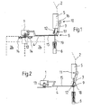
- a locking arrangement as provided by the invention and illustrated by the drawings comprises a lock 1 whose locking bar 13 latches the lock plates 14 mounted on the elevator doors so as to render them immovable.
- a lever mechanism 4 comprising a straight bar 15, one end of which is pivoted on one end 8 of an actuating lever 7, the other end 10 of this lever being provided with a bearing roller 16 which, in certain positions, leans against the guide surfaces 2 provided in the landing zones.
- the actuating lever 7 is pivoted at point 17 on a bell crank 9, which in turn is pivoted at point 18 (fig. 2) on the frame of the device.
- the arrangement comprises an electromagnet used as an actuator 5 and a spring used as a counter device 6, said components being connected by a connecting rod 19.
- the bell crank 9 is linked with the connecting rod 19 by a lever structure 12 consisting of a first arm rigidly joined with the bell crank and a second arm linking the free end of the first lever with the connecting rod 19, so that when the connecting rod is moved by the electromagnet or the counter spring, the lever structure 12 will cause the bell crank 9 to turn about its fulcrum 18.
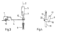
- Fig. 4 illustrates the principle of the arrangement of the bell crank 9 and the lever structure 12.
- the bell crank 9 consists of a rigid angular body pivoted by its elbow 18 on the frame of the arrangement, one end 17 of the angular body being connected to the actuating lever 7 and the other end 22 to the lever structure 12 linking this end of the bell crank with the connecting rod 19.
- the motion of the connecting rod 19 will cause the bell crank to turn about point 18, thereby shifting the position of the fulcrum 17 of the actuating lever 7.
- the locking arrangement of the invention functions as follows.
- a voltage is supplied to the magnet 5, which therefore attracts the connecting rod 19, causing the lever structure 12 to turn the bell crank 9 to the position shown in fig. 1.
- a clearance is produced between the bearing roller 16 and the guide surface 5. Because of this clearance, the floors where the elevator will not stop can be passed by without the bearing roller 16 hitting the guide surfaces, resulting in a smoother and quieter elevator travel.
- the spring-loaded locking bar 13 of the lock 1 is in its lower position, locking both door leaves 24 by means of lock plates 14.
- Fig. 3 illustrates a situation where the magnet 5 has released, i.e. the spring 6 has drawn the connecting rod 19 to the lower position. Since the actuating lever 7 is outside the region of the guide surface 2, no bearing is provided for the actuating lever 7, which is why bar 15 receives no thrust that would open the lock 1. This corresponds to a situation where the elevator car has stopped between landings e.g. due to a power failure.
- the arrangement of the invention allows the fulcrum 17 of the actuating lever 7 to be shifted to different positions in different situations, so that the actuating lever 7 will act in the desired manner, i.e. the door lock will only unlatch when the car is at a landing, and even then only if desired.
Landscapes
- Elevator Door Apparatuses (AREA)
- Maintenance And Inspection Apparatuses For Elevators (AREA)
- Cage And Drive Apparatuses For Elevators (AREA)
- Steroid Compounds (AREA)
Applications Claiming Priority (2)
| Application Number | Priority Date | Filing Date | Title |
|---|---|---|---|
| FI895147 | 1989-10-30 | ||
| FI895147A FI85363C (fi) | 1989-10-30 | 1989-10-30 | Laosningsanordning foer doerr i hisskorg. |
Publications (3)
| Publication Number | Publication Date |
|---|---|
| EP0426057A2 true EP0426057A2 (fr) | 1991-05-08 |
| EP0426057A3 EP0426057A3 (en) | 1992-07-22 |
| EP0426057B1 EP0426057B1 (fr) | 1995-08-23 |
Family
ID=8529253
Family Applications (1)
| Application Number | Title | Priority Date | Filing Date |
|---|---|---|---|
| EP90120656A Expired - Lifetime EP0426057B1 (fr) | 1989-10-30 | 1990-10-27 | Arrangement de verrouillage d'une porte d'une cabine d'ascenseur |
Country Status (4)
| Country | Link |
|---|---|
| EP (1) | EP0426057B1 (fr) |
| AT (1) | ATE126780T1 (fr) |
| DE (2) | DE426057T1 (fr) |
| FI (1) | FI85363C (fr) |
Cited By (3)
| Publication number | Priority date | Publication date | Assignee | Title |
|---|---|---|---|---|
| EP0709334A1 (fr) * | 1994-10-31 | 1996-05-01 | Kone Oy | Appareil de verrouillage de la porte d'une cabine d'ascenseur et procédé pour bloquer et débloquer une porte de cabine |
| US7252179B2 (en) | 2002-04-22 | 2007-08-07 | Wittur Ag | Elevator-door latching and opening device |
| CN102502382A (zh) * | 2011-12-26 | 2012-06-20 | 日立电梯(中国)有限公司 | 重锤式轿厢门锁机构 |
Family Cites Families (6)
| Publication number | Priority date | Publication date | Assignee | Title |
|---|---|---|---|---|
| GB352750A (en) * | 1930-07-24 | 1931-07-16 | Schindler & Co | Improvements in safety locking devices for lift shaft doors |
| DE598407C (de) * | 1932-04-08 | 1934-06-09 | Ohg Stigler | Zusatzanordnung fuer Sicherheitsschloesser von Aufzugstueren |
| GB1047977A (en) * | 1964-09-01 | 1966-11-09 | Ace Machinery Ltd | Improvements in or relating to hoists |
| US4512443A (en) * | 1982-03-24 | 1985-04-23 | Dewhurst & Partner P.L.C. | Lift door control apparatus |
| GB2206331B (en) * | 1987-05-26 | 1991-10-02 | Otis Elevator Plc | Elevator car door locking mechanism |
| JPS6422791A (en) * | 1987-07-18 | 1989-01-25 | Mitsubishi Electric Corp | Door locking device for elevator |
-
1989
- 1989-10-30 FI FI895147A patent/FI85363C/fi not_active IP Right Cessation
-
1990
- 1990-10-27 DE DE199090120656T patent/DE426057T1/de active Pending
- 1990-10-27 DE DE69021827T patent/DE69021827T2/de not_active Expired - Fee Related
- 1990-10-27 AT AT90120656T patent/ATE126780T1/de active
- 1990-10-27 EP EP90120656A patent/EP0426057B1/fr not_active Expired - Lifetime
Cited By (6)
| Publication number | Priority date | Publication date | Assignee | Title |
|---|---|---|---|---|
| EP0709334A1 (fr) * | 1994-10-31 | 1996-05-01 | Kone Oy | Appareil de verrouillage de la porte d'une cabine d'ascenseur et procédé pour bloquer et débloquer une porte de cabine |
| US5690189A (en) * | 1994-10-31 | 1997-11-25 | Kone Oy | Apparatus and method for locking and unlocking the door of an elevator car |
| CN1099995C (zh) * | 1994-10-31 | 2003-01-29 | 科恩股份公司 | 闭锁电梯厢门的装置及开闭厢门的方法 |
| US7252179B2 (en) | 2002-04-22 | 2007-08-07 | Wittur Ag | Elevator-door latching and opening device |
| CN102502382A (zh) * | 2011-12-26 | 2012-06-20 | 日立电梯(中国)有限公司 | 重锤式轿厢门锁机构 |
| CN102502382B (zh) * | 2011-12-26 | 2013-08-14 | 日立电梯(中国)有限公司 | 重锤式轿厢门锁机构 |
Also Published As
| Publication number | Publication date |
|---|---|
| DE69021827T2 (de) | 1996-03-21 |
| EP0426057B1 (fr) | 1995-08-23 |
| EP0426057A3 (en) | 1992-07-22 |
| DE69021827D1 (de) | 1995-09-28 |
| FI85363B (fi) | 1991-12-31 |
| DE426057T1 (de) | 1991-11-28 |
| FI85363C (fi) | 1992-04-10 |
| ATE126780T1 (de) | 1995-09-15 |
| FI895147A0 (fi) | 1989-10-30 |
Similar Documents
| Publication | Publication Date | Title |
|---|---|---|
| EP0709334B1 (fr) | Appareil de verrouillage de la porte d'une cabine d'ascenseur et procédé pour bloquer et débloquer une porte de cabine | |
| US4934488A (en) | Door lock for an elevator car | |
| US6168216B1 (en) | Vehicle door latch device | |
| US5174417A (en) | Device and method for the actuating and unlatching of the shaft doors of an elevator | |
| US6386597B1 (en) | Dual latch retraction system for exit bar | |
| KR100373242B1 (ko) | 슬라이딩 도어의 록킹콘트롤러 | |
| US20050218661A1 (en) | Motor vehicle lock | |
| MX9202212A (es) | Dispositivo accionador de puerta con mecanismo bloqueador para elevadores. | |
| US5139112A (en) | Elevator car door lock | |
| US6688042B2 (en) | Central lock mechanism | |
| EP0850189B1 (fr) | Procedure d'actionnement de la porte paliere d'un ascenseur, et dispositif d'accouplement de porte | |
| AU2004321993A1 (en) | Electromagnetically operated elevator door lock | |
| EP0426057A2 (fr) | Arrangement de verrouillage d'une porte d'une cabine d'ascenseur | |
| CN102782236A (zh) | 解锁装置 | |
| KR20010012676A (ko) | 도어 메카니즘 | |
| US20250382157A1 (en) | Elevator | |
| US5105916A (en) | Elevator door coupling device | |
| EP1290301B1 (fr) | Procede et appareil pour verrou | |
| EP0484171B1 (fr) | Système d'une porte d'un ascenseur | |
| US312575A (en) | Door-latch | |
| US759703A (en) | Safety-lock for elevator-shafts. | |
| CA2048552A1 (fr) | Methode d'impregnation du fer avec une matiere resistant a l'usure |
Legal Events
| Date | Code | Title | Description |
|---|---|---|---|
| PUAI | Public reference made under article 153(3) epc to a published international application that has entered the european phase |
Free format text: ORIGINAL CODE: 0009012 |
|
| 17P | Request for examination filed |
Effective date: 19901228 |
|
| AK | Designated contracting states |
Kind code of ref document: A2 Designated state(s): AT BE DE FR GB IT NL SE |
|
| TCAT | At: translation of patent claims filed | ||
| ITCL | It: translation for ep claims filed |
Representative=s name: JACOBACCI CASETTA & PERANI S.P.A. |
|
| EL | Fr: translation of claims filed | ||
| TCNL | Nl: translation of patent claims filed | ||
| DET | De: translation of patent claims | ||
| PUAL | Search report despatched |
Free format text: ORIGINAL CODE: 0009013 |
|
| AK | Designated contracting states |
Kind code of ref document: A3 Designated state(s): AT BE DE FR GB IT NL SE |
|
| 17Q | First examination report despatched |
Effective date: 19940520 |
|
| GRAA | (expected) grant |
Free format text: ORIGINAL CODE: 0009210 |
|
| AK | Designated contracting states |
Kind code of ref document: B1 Designated state(s): AT BE DE FR GB IT NL SE |
|
| REF | Corresponds to: |
Ref document number: 126780 Country of ref document: AT Date of ref document: 19950915 Kind code of ref document: T |
|
| REF | Corresponds to: |
Ref document number: 69021827 Country of ref document: DE Date of ref document: 19950928 |
|
| ITF | It: translation for a ep patent filed | ||
| ET | Fr: translation filed | ||
| PLBE | No opposition filed within time limit |
Free format text: ORIGINAL CODE: 0009261 |
|
| STAA | Information on the status of an ep patent application or granted ep patent |
Free format text: STATUS: NO OPPOSITION FILED WITHIN TIME LIMIT |
|
| 26N | No opposition filed | ||
| PGFP | Annual fee paid to national office [announced via postgrant information from national office to epo] |
Ref country code: FR Payment date: 19980911 Year of fee payment: 9 |
|
| PGFP | Annual fee paid to national office [announced via postgrant information from national office to epo] |
Ref country code: SE Payment date: 19980914 Year of fee payment: 9 |
|
| PGFP | Annual fee paid to national office [announced via postgrant information from national office to epo] |
Ref country code: AT Payment date: 19980915 Year of fee payment: 9 |
|
| PGFP | Annual fee paid to national office [announced via postgrant information from national office to epo] |
Ref country code: GB Payment date: 19980917 Year of fee payment: 9 |
|
| PGFP | Annual fee paid to national office [announced via postgrant information from national office to epo] |
Ref country code: NL Payment date: 19980923 Year of fee payment: 9 |
|
| PGFP | Annual fee paid to national office [announced via postgrant information from national office to epo] |
Ref country code: DE Payment date: 19980925 Year of fee payment: 9 |
|
| PGFP | Annual fee paid to national office [announced via postgrant information from national office to epo] |
Ref country code: BE Payment date: 19981016 Year of fee payment: 9 |
|
| PG25 | Lapsed in a contracting state [announced via postgrant information from national office to epo] |
Ref country code: GB Free format text: LAPSE BECAUSE OF NON-PAYMENT OF DUE FEES Effective date: 19991027 Ref country code: AT Free format text: LAPSE BECAUSE OF NON-PAYMENT OF DUE FEES Effective date: 19991027 |
|
| PG25 | Lapsed in a contracting state [announced via postgrant information from national office to epo] |
Ref country code: SE Free format text: THE PATENT HAS BEEN ANNULLED BY A DECISION OF A NATIONAL AUTHORITY Effective date: 19991030 |
|
| PG25 | Lapsed in a contracting state [announced via postgrant information from national office to epo] |
Ref country code: BE Free format text: LAPSE BECAUSE OF NON-PAYMENT OF DUE FEES Effective date: 19991031 |
|
| BERE | Be: lapsed |
Owner name: KONE ELEVATOR G.M.B.H. Effective date: 19991031 |
|
| PG25 | Lapsed in a contracting state [announced via postgrant information from national office to epo] |
Ref country code: NL Free format text: LAPSE BECAUSE OF NON-PAYMENT OF DUE FEES Effective date: 20000501 |
|
| GBPC | Gb: european patent ceased through non-payment of renewal fee |
Effective date: 19991027 |
|
| EUG | Se: european patent has lapsed |
Ref document number: 90120656.5 |
|
| PG25 | Lapsed in a contracting state [announced via postgrant information from national office to epo] |
Ref country code: FR Free format text: LAPSE BECAUSE OF NON-PAYMENT OF DUE FEES Effective date: 20000630 |
|
| NLV4 | Nl: lapsed or anulled due to non-payment of the annual fee |
Effective date: 20000501 |
|
| PG25 | Lapsed in a contracting state [announced via postgrant information from national office to epo] |
Ref country code: DE Free format text: LAPSE BECAUSE OF NON-PAYMENT OF DUE FEES Effective date: 20000801 |
|
| REG | Reference to a national code |
Ref country code: FR Ref legal event code: ST |
|
| PG25 | Lapsed in a contracting state [announced via postgrant information from national office to epo] |
Ref country code: IT Free format text: LAPSE BECAUSE OF NON-PAYMENT OF DUE FEES;WARNING: LAPSES OF ITALIAN PATENTS WITH EFFECTIVE DATE BEFORE 2007 MAY HAVE OCCURRED AT ANY TIME BEFORE 2007. THE CORRECT EFFECTIVE DATE MAY BE DIFFERENT FROM THE ONE RECORDED. Effective date: 20051027 |