EP0426223A1 - Non-return valve of the flap type for flow concentration - Google Patents
Non-return valve of the flap type for flow concentration Download PDFInfo
- Publication number
- EP0426223A1 EP0426223A1 EP90202740A EP90202740A EP0426223A1 EP 0426223 A1 EP0426223 A1 EP 0426223A1 EP 90202740 A EP90202740 A EP 90202740A EP 90202740 A EP90202740 A EP 90202740A EP 0426223 A1 EP0426223 A1 EP 0426223A1
- Authority
- EP
- European Patent Office
- Prior art keywords
- units
- flap valve
- modular
- way flap
- adjacent
- Prior art date
- Legal status (The legal status is an assumption and is not a legal conclusion. Google has not performed a legal analysis and makes no representation as to the accuracy of the status listed.)
- Withdrawn
Links
- 230000006698 induction Effects 0.000 claims abstract description 9
- 238000002485 combustion reaction Methods 0.000 claims abstract description 8
- 230000001154 acute effect Effects 0.000 claims description 2
- 239000000203 mixture Substances 0.000 description 4
- 230000036961 partial effect Effects 0.000 description 4
- 230000006835 compression Effects 0.000 description 3
- 238000007906 compression Methods 0.000 description 3
- 239000007789 gas Substances 0.000 description 2
- 230000003247 decreasing effect Effects 0.000 description 1
- 230000000694 effects Effects 0.000 description 1
- 238000002347 injection Methods 0.000 description 1
- 239000007924 injection Substances 0.000 description 1
- 238000009434 installation Methods 0.000 description 1
- 230000001737 promoting effect Effects 0.000 description 1
- 230000002829 reductive effect Effects 0.000 description 1
- 230000000452 restraining effect Effects 0.000 description 1
- 230000002441 reversible effect Effects 0.000 description 1
Images
Classifications
-
- F—MECHANICAL ENGINEERING; LIGHTING; HEATING; WEAPONS; BLASTING
- F04—POSITIVE - DISPLACEMENT MACHINES FOR LIQUIDS; PUMPS FOR LIQUIDS OR ELASTIC FLUIDS
- F04B—POSITIVE-DISPLACEMENT MACHINES FOR LIQUIDS; PUMPS
- F04B39/00—Component parts, details, or accessories, of pumps or pumping systems specially adapted for elastic fluids, not otherwise provided for in, or of interest apart from, groups F04B25/00 - F04B37/00
- F04B39/10—Adaptations or arrangements of distribution members
- F04B39/1073—Adaptations or arrangements of distribution members the members being reed valves
-
- F—MECHANICAL ENGINEERING; LIGHTING; HEATING; WEAPONS; BLASTING
- F01—MACHINES OR ENGINES IN GENERAL; ENGINE PLANTS IN GENERAL; STEAM ENGINES
- F01L—CYCLICALLY OPERATING VALVES FOR MACHINES OR ENGINES
- F01L3/00—Lift-valve, i.e. cut-off apparatus with closure members having at least a component of their opening and closing motion perpendicular to the closing faces; Parts or accessories thereof
- F01L3/20—Shapes or constructions of valve members, not provided for in preceding subgroups of this group
- F01L3/205—Reed valves
-
- F—MECHANICAL ENGINEERING; LIGHTING; HEATING; WEAPONS; BLASTING
- F16—ENGINEERING ELEMENTS AND UNITS; GENERAL MEASURES FOR PRODUCING AND MAINTAINING EFFECTIVE FUNCTIONING OF MACHINES OR INSTALLATIONS; THERMAL INSULATION IN GENERAL
- F16K—VALVES; TAPS; COCKS; ACTUATING-FLOATS; DEVICES FOR VENTING OR AERATING
- F16K15/00—Check valves
- F16K15/14—Check valves with flexible valve members
- F16K15/16—Check valves with flexible valve members with tongue-shaped laminae
Definitions
- the present invention relates to a non-return valve of the flap type for flow concentration, particularly for use in engines of the internal combustion type.
- the inlet valves are opened while the discharge valves are still open (crossover), and while this promotes the discharge or the spent gases trom the cylinders at certain speeds, at other speeds it causes a return of the spent gases from the exhaust system to the cylinders and even into the induction pipes, thus decreasing the volumetric efficiency of the engine.
- the inlet valves are closed by inertial and resonance effects after the start of the compression stroke.
- the induction pipes should be provided with non-return valves capable of permitting the flow of air or mixture into the cylinders and of preventing a reverse flow to the exterior, restraining the charge flowing back from the cylinder into the induction pipes.
- non-return valves of the flap type known in the previous art have been used; however, these have the disadvantage of feeding inio the induction pipes volumes of air which flow in parallel entry directions as a result of the uniform orientation of the exit direction of the air flow from the flap units of the valves; the volumes of air supplied in this way have a very wide flow section, a low relative density, and a low velocity of entry into the combustion chambers of the cylinders, particularly at low speeds, and consequently the air flow may become turbulent, thus counteracting the desired injection of mixture into the combustion chambers of the cylinders, while promoting, as a result of the low inertia of the air supplied in this way, the return of air into the feed pipe during the time interval required for the cylinders to enter the compression phase and close the inlet valves.
- a non-return valve which specifies a one-way flap valve particularly for inlet pipes of cylinders of internal combustion engines of vehicles, comprising a number of modular passage units having substantially curved base walls and having internal dividers parallel to the side walls and capable of engaging frontally with flexible air-tight closure flaps to form air flow channels: these modular units arc arranged in the inlet pipe in various positions, with at least one of them having an outlet flow direction different from and convergent towards that of the other units, a distance piece having a profile curved according to the deformation curve of each flap of the adjacent units being placed between the unit with a different outflow direction and the adjacent unit.
- the modular units are arranged with outlet directions which may be symmetrical about a plane or about two planes perpendicular to each other, or perpendicular to planes at acute angles to each other.
- the distance piece of adjacent modular units with different and convergent outlet directions should preferably be extended into a feed pipe supplying air to the one-way flap valve to form a bulkhead dividing the feed flow and directing it towards the individual flow channels of the valve.
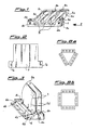
- a preferred form of the non-return valve 1 consists of a set of modular passage units 2 having substantially C-shaped sections with curved base walls 2a and internal dividing walls 2b arranged parallel to the side walls 2d of the unit 2, to form a set of air flow channels 3.
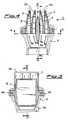
- each unit 2 On the lower part of each unit 2 there are integrally formed blocks 4 having axial holes 4b and transverse holes 4a to allow connection to each other and to a stepped end piece 6 (Fig. 2) which also has transverse holes 6a for the passage of a suitable fastening element to secure the units 2 as a single block and axial holes 6b for the passage of means of fastening to the fixed body of the engine for the installation of the valve 1.
- the blocks 4 also have transverse dimensions greater than the corresponding dimension of the block 2, thus providing a step 4c extending across the whole width of the unit 2.
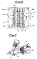
- Flexible flaps 7, in the form of an inverted T, and also having holes 7a for the passage of the fastening means, are arranged so that they contact the upper surfaces 2c of the dividing walls 2b and side walls 2d; when the assembly of the whole valve unit is complete, these flaps 7 are held in place by the step 4c and form an air-tight closure of the flow channels 3.
- the valve 1 consists of two pairs of modular passage units 2 whose flow channels 3 are closed in an air-tight manner by the flaps 7 and and are orientated with the outlet directions of the flow converging towards a single central plane of symmetry, while the central and adjacent units 2 are spaced from the centre by a distance piece 5 which itself has a profile with external walls curved according to the curve of deformation of the flaps 7 for which they provide a stop.
- the distance piece ih extended downwards by the part 8b towards the interior of a part 9 forming the air feed pipe to the valve; the distance piece 8 is also provided with holes 8a for the passage of the element which fastens and secures the whole valve unit; this element is not illustrated in the figure.
- valve unit 1 described above Ls fitted, in a way which is known and is therefore not detailed in the figure, to the feed pipe 10 of an inlet valve 11 immediately downstream of the inector 12; when the inlet valve 11 is opened to allow the induction of mixture, the pressure drop due to the action of the piston causes the deflection of the flaps 7, which lie against the curved wall 2a immediately downstream, thus permitting the passage of the air flow which, with the valve configuration described, has a very small surface section in relation to the section of a flow in a normal valve arrangement.
- modular units 2 to form the non-return valve 1 may be arranged in a triangular configuration (Fig. 5a), or with symmetrical flow directions with respect to two planes which are perpendicular to each other, forming, for example, a square configuration (Fig. 8b).
Landscapes
- Engineering & Computer Science (AREA)
- General Engineering & Computer Science (AREA)
- Mechanical Engineering (AREA)
- Physics & Mathematics (AREA)
- Geometry (AREA)
- Characterised By The Charging Evacuation (AREA)
- Check Valves (AREA)
- Enzymes And Modification Thereof (AREA)
- Temperature-Responsive Valves (AREA)
- Safety Valves (AREA)
Applications Claiming Priority (2)
| Application Number | Priority Date | Filing Date | Title |
|---|---|---|---|
| IT2202489U | 1989-10-31 | ||
| IT22024U IT218931Z2 (it) | 1989-10-31 | 1989-10-31 | Valvola di non ritorno di tipo lamellare a concentrazione di flusso |
Publications (1)
| Publication Number | Publication Date |
|---|---|
| EP0426223A1 true EP0426223A1 (en) | 1991-05-08 |
Family
ID=11190355
Family Applications (1)
| Application Number | Title | Priority Date | Filing Date |
|---|---|---|---|
| EP90202740A Withdrawn EP0426223A1 (en) | 1989-10-31 | 1990-10-15 | Non-return valve of the flap type for flow concentration |
Country Status (4)
| Country | Link |
|---|---|
| US (1) | US5027754A (it) |
| EP (1) | EP0426223A1 (it) |
| JP (1) | JPH03172520A (it) |
| IT (1) | IT218931Z2 (it) |
Cited By (11)
| Publication number | Priority date | Publication date | Assignee | Title |
|---|---|---|---|---|
| US6858127B2 (en) | 2001-03-05 | 2005-02-22 | Shell Oil Company | Process for the preparation of middle distillates |
| EP1504209A4 (en) * | 2002-05-10 | 2005-10-19 | Moto Tassinari Inc | VALVE VALVE ASSEMBLY |
| EP1626080A2 (en) | 2001-03-05 | 2006-02-15 | Shell Internationale Researchmaatschappij B.V. | Hydraulic fluid composition |
| US7285206B2 (en) | 2001-03-05 | 2007-10-23 | Shell Oil Company | Process to prepare a lubricating base oil and a gas oil |
| US7300565B2 (en) | 2002-07-18 | 2007-11-27 | Shell Oil Company | Process to prepare a microcrystalline wax and a middle distillate fuel |
| US7473347B2 (en) | 2001-03-05 | 2009-01-06 | Shell Oil Company | Process to prepare a lubricating base oil |
| US7531081B2 (en) | 2001-02-13 | 2009-05-12 | Shell Oil Company | Base oil composition |
| EP2496869A4 (en) * | 2009-11-18 | 2013-05-22 | Zahroof Corp | SYSTEMS AND METHOD FOR A FLAT VALVE MODULE AND VALVE ASSEMBLY THEREWITH |
| CN105840896A (zh) * | 2016-05-20 | 2016-08-10 | 上海科勒电子科技有限公司 | 防滴水装置及水龙头 |
| US10995866B2 (en) | 2017-06-30 | 2021-05-04 | Zahroof Valves Inc. | Stacked valve assembly |
| CN114893581A (zh) * | 2022-05-23 | 2022-08-12 | 烟台杰瑞石油装备技术有限公司 | 旋塞阀及压裂设备 |
Families Citing this family (10)
| Publication number | Priority date | Publication date | Assignee | Title |
|---|---|---|---|---|
| US5083531A (en) * | 1990-07-09 | 1992-01-28 | Steve Gregory | Removable inlet shape for internal combustion engine |
| US5253617A (en) * | 1992-09-03 | 1993-10-19 | Capsonic Group Inc. | Reed valve assembly for an intake manifold and method of assembly |
| DK1691735T3 (da) * | 2003-11-19 | 2010-05-31 | Coloplast As | Indretning til tilvejebringelse af antirefluks i et kropsvæskeopsamlings- og/eller prøvetagningssystem og fremgangsmåde til fremstilling af en sådan indretning |
| US7028649B1 (en) | 2004-03-04 | 2006-04-18 | Polaris Industries Inc. | High flow reed valve assembly for a two-cycle engine |
| US7458344B2 (en) * | 2004-11-01 | 2008-12-02 | Brad Holtorf | Motorcycle engine method and apparatus |
| US8141538B2 (en) * | 2008-12-12 | 2012-03-27 | Chung-Yu Yang | Intake ducting device for a car engine |
| JP5988236B2 (ja) * | 2011-08-30 | 2016-09-07 | 俊彦 山本 | エンジンの吸気装置 |
| US8997721B2 (en) * | 2011-08-30 | 2015-04-07 | Toshihiko Yamamoto | Intake apparatus of engine |
| US9464605B2 (en) * | 2013-08-24 | 2016-10-11 | Lonn M. Peterson | Quad flow torque enhancement flow divider causing improved fuel/air transfer |
| US9664151B1 (en) * | 2016-04-08 | 2017-05-30 | Kao-Shan Lin | Air admission device for combustion equipment |
Citations (4)
| Publication number | Priority date | Publication date | Assignee | Title |
|---|---|---|---|---|
| FR2040829A5 (it) * | 1969-04-15 | 1971-01-22 | Le N | |
| US4228770A (en) * | 1979-05-29 | 1980-10-21 | Performance Industries, Inc. | Internal combustion engine fuel supply system |
| FR2492497A3 (fr) * | 1980-10-17 | 1982-04-23 | Alfa Romeo Spa | Dispositif a effet de clapet anti-retour |
| EP0337520A1 (en) * | 1988-03-14 | 1989-10-18 | FIAT AUTO S.p.A. | Valve unit for an internal combustion engine intake duct, comprising non-return flap valves |
Family Cites Families (6)
| Publication number | Priority date | Publication date | Assignee | Title |
|---|---|---|---|---|
| CA547305A (en) * | 1957-10-08 | J. Oxnam George | Non-return valves | |
| US1672436A (en) * | 1925-07-02 | 1928-06-05 | Atlas Diesel Ab | Automatically-operating scavenging valve for two-stroke cycle internal-combustion engines applicable also to compressors and the like |
| SU889878A1 (ru) * | 1980-03-31 | 1981-12-15 | Коломенский Филиал Всесоюзного Заочного Политехнического Института | Двигатель внутреннего сгорани |
| IT1133711B (it) * | 1980-10-17 | 1986-07-09 | Alfa Romeo Spa | Condotto di aspirazione munito di mezzi valvolari di non ritorno |
| US4474145A (en) * | 1983-08-10 | 1984-10-02 | Performance Industries, Inc. | Fuel supply system for internal combustion engine |
| US4879976A (en) * | 1987-09-09 | 1989-11-14 | Performance Industries, Inc. | Reed valve mechanism for engines |
-
1989
- 1989-10-31 IT IT22024U patent/IT218931Z2/it active IP Right Grant
-
1990
- 1990-10-15 EP EP90202740A patent/EP0426223A1/en not_active Withdrawn
- 1990-10-16 JP JP2275469A patent/JPH03172520A/ja active Pending
- 1990-10-18 US US07/599,487 patent/US5027754A/en not_active Expired - Fee Related
Patent Citations (4)
| Publication number | Priority date | Publication date | Assignee | Title |
|---|---|---|---|---|
| FR2040829A5 (it) * | 1969-04-15 | 1971-01-22 | Le N | |
| US4228770A (en) * | 1979-05-29 | 1980-10-21 | Performance Industries, Inc. | Internal combustion engine fuel supply system |
| FR2492497A3 (fr) * | 1980-10-17 | 1982-04-23 | Alfa Romeo Spa | Dispositif a effet de clapet anti-retour |
| EP0337520A1 (en) * | 1988-03-14 | 1989-10-18 | FIAT AUTO S.p.A. | Valve unit for an internal combustion engine intake duct, comprising non-return flap valves |
Cited By (19)
| Publication number | Priority date | Publication date | Assignee | Title |
|---|---|---|---|---|
| US7531081B2 (en) | 2001-02-13 | 2009-05-12 | Shell Oil Company | Base oil composition |
| US7670996B2 (en) | 2001-02-13 | 2010-03-02 | Shell Oil Company | Lubricant composition having a base oil and one or more additives, wherein the base oil has been obtained from waxy paraffinic fischer-tropsch synthesized hydrocarbons |
| US7473347B2 (en) | 2001-03-05 | 2009-01-06 | Shell Oil Company | Process to prepare a lubricating base oil |
| EP1626080A2 (en) | 2001-03-05 | 2006-02-15 | Shell Internationale Researchmaatschappij B.V. | Hydraulic fluid composition |
| EP1630221A1 (en) | 2001-03-05 | 2006-03-01 | Shell Internationale Researchmaatschappij B.V. | Lubricating grease composition comprising a base oil prepared from a Fischer-Tropsch product |
| US7285206B2 (en) | 2001-03-05 | 2007-10-23 | Shell Oil Company | Process to prepare a lubricating base oil and a gas oil |
| EP1630222A1 (en) | 2001-03-05 | 2006-03-01 | Shell Internationale Researchmaatschappij B.V. | Turbine fluid composition comprising a base oil prepared from a Fischer-Tropsch product |
| US7332072B2 (en) | 2001-03-05 | 2008-02-19 | Shell Oil Company | Process to prepare a waxy raffinate |
| US6858127B2 (en) | 2001-03-05 | 2005-02-22 | Shell Oil Company | Process for the preparation of middle distillates |
| US7497941B2 (en) | 2001-03-05 | 2009-03-03 | Shell Oil Company | Process to prepare a lubricating base oil and a gas oil |
| EP1504209A4 (en) * | 2002-05-10 | 2005-10-19 | Moto Tassinari Inc | VALVE VALVE ASSEMBLY |
| US7300565B2 (en) | 2002-07-18 | 2007-11-27 | Shell Oil Company | Process to prepare a microcrystalline wax and a middle distillate fuel |
| EP2496869A4 (en) * | 2009-11-18 | 2013-05-22 | Zahroof Corp | SYSTEMS AND METHOD FOR A FLAT VALVE MODULE AND VALVE ASSEMBLY THEREWITH |
| US9989161B2 (en) | 2009-11-18 | 2018-06-05 | Zahroof Valves, Inc. | Systems and methods for a reed valve module and valve assembly |
| US11002377B2 (en) | 2009-11-18 | 2021-05-11 | Zahroof Valves Inc. | Systems and methods for a reed valve module and a modular reed valve assembly |
| CN105840896A (zh) * | 2016-05-20 | 2016-08-10 | 上海科勒电子科技有限公司 | 防滴水装置及水龙头 |
| US10443752B2 (en) | 2016-05-20 | 2019-10-15 | Shanghai Kohler Electronics, Ltd. | Drip proof outlet diffuser for a faucet |
| US10995866B2 (en) | 2017-06-30 | 2021-05-04 | Zahroof Valves Inc. | Stacked valve assembly |
| CN114893581A (zh) * | 2022-05-23 | 2022-08-12 | 烟台杰瑞石油装备技术有限公司 | 旋塞阀及压裂设备 |
Also Published As
| Publication number | Publication date |
|---|---|
| IT218931Z2 (it) | 1992-11-10 |
| IT8922024V0 (it) | 1989-10-31 |
| US5027754A (en) | 1991-07-02 |
| IT8922024U1 (it) | 1991-05-01 |
| JPH03172520A (ja) | 1991-07-25 |
Similar Documents
| Publication | Publication Date | Title |
|---|---|---|
| US5027754A (en) | Non-return valve of the flap type for flow concentration | |
| EP1290328B1 (en) | Method and device for exhaust recycling and supercharged diesel engine | |
| EP0384359B1 (en) | Intergrated tuned induction system | |
| US9915191B2 (en) | Air intake system for internal combustion engine | |
| US4422416A (en) | Intake duct fitted with non-return valve means | |
| US6478008B2 (en) | Piston-type internal combustion engine having a subdivided gas-intake port | |
| JP2018021557A (ja) | 排気ガス後処理装置及び方法 | |
| US5081965A (en) | Intake valve for internal combustion engine | |
| ITRM990714A1 (it) | Motore a combustione interna, in particolare per veicoli con ricircolo dei gas di scarico. | |
| JPS63500323A (ja) | 燃焼室を有する火花点火式内燃機関に液体燃料を噴射する方法 | |
| GB2043779A (en) | Internal combustion engine exhaust passage | |
| US3273551A (en) | Cylinder inlet passage for an internal combustion engine | |
| US5718195A (en) | Intake pipe for internal combustion engine | |
| EP1219812B1 (en) | Fuel injection device for internal combustion engine | |
| EP0337520B1 (en) | Valve unit for an internal combustion engine intake duct, comprising non-return flap valves | |
| US6109234A (en) | Cylinder head intake system | |
| JP2005511945A (ja) | 直接噴射式火花点火内燃機関のために給気成層を用いる燃焼方法 | |
| JPS63230946A (ja) | 内燃機関の多気筒エンジンブロック | |
| US6173693B1 (en) | Cylinder head | |
| US5651344A (en) | Induction and injection system for multi-valve engine | |
| DE19642685A1 (de) | Einrichtung zur Abgasrückführung und Sekundärluftzufuhr für eine Brennkraftmaschine | |
| EP0723074B1 (en) | Cylinder head for an internal combustion engine | |
| US5601062A (en) | Intake system for engine | |
| JPH02223635A (ja) | シリンダ当り2つの給気弁を有する内燃機関 | |
| JPH03182623A (ja) | 内燃機関の吸気装置 |
Legal Events
| Date | Code | Title | Description |
|---|---|---|---|
| PUAI | Public reference made under article 153(3) epc to a published international application that has entered the european phase |
Free format text: ORIGINAL CODE: 0009012 |
|
| AK | Designated contracting states |
Kind code of ref document: A1 Designated state(s): AT BE CH DE FR GB IT LI LU NL SE |
|
| 17P | Request for examination filed |
Effective date: 19911029 |
|
| 17Q | First examination report despatched |
Effective date: 19921016 |
|
| STAA | Information on the status of an ep patent application or granted ep patent |
Free format text: STATUS: THE APPLICATION HAS BEEN WITHDRAWN |
|
| 18W | Application withdrawn |
Withdrawal date: 19930416 |