EP0426231A2 - Analysis of drilling solids samples - Google Patents
Analysis of drilling solids samples Download PDFInfo
- Publication number
- EP0426231A2 EP0426231A2 EP90202795A EP90202795A EP0426231A2 EP 0426231 A2 EP0426231 A2 EP 0426231A2 EP 90202795 A EP90202795 A EP 90202795A EP 90202795 A EP90202795 A EP 90202795A EP 0426231 A2 EP0426231 A2 EP 0426231A2
- Authority
- EP
- European Patent Office
- Prior art keywords
- solids
- mud
- sample
- accordance
- drilled
- Prior art date
- Legal status (The legal status is an assumption and is not a legal conclusion. Google has not performed a legal analysis and makes no representation as to the accuracy of the status listed.)
- Withdrawn
Links
Images


Classifications
-
- E—FIXED CONSTRUCTIONS
- E21—EARTH OR ROCK DRILLING; MINING
- E21B—EARTH OR ROCK DRILLING; OBTAINING OIL, GAS, WATER, SOLUBLE OR MELTABLE MATERIALS OR A SLURRY OF MINERALS FROM WELLS
- E21B49/00—Testing the nature of borehole walls; Formation testing; Methods or apparatus for obtaining samples of soil or well fluids, specially adapted to earth drilling or wells
- E21B49/005—Testing the nature of borehole walls or the formation by using drilling mud or cutting data
-
- G—PHYSICS
- G01—MEASURING; TESTING
- G01N—INVESTIGATING OR ANALYSING MATERIALS BY DETERMINING THEIR CHEMICAL OR PHYSICAL PROPERTIES
- G01N15/00—Investigating characteristics of particles; Investigating permeability, pore-volume or surface-area of porous materials
- G01N15/06—Investigating concentration of particle suspensions
-
- G—PHYSICS
- G01—MEASURING; TESTING
- G01N—INVESTIGATING OR ANALYSING MATERIALS BY DETERMINING THEIR CHEMICAL OR PHYSICAL PROPERTIES
- G01N21/00—Investigating or analysing materials by the use of optical means, i.e. using sub-millimetre waves, infrared, visible or ultraviolet light
- G01N21/17—Systems in which incident light is modified in accordance with the properties of the material investigated
- G01N21/25—Colour; Spectral properties, i.e. comparison of effect of material on the light at two or more different wavelengths or wavelength bands
- G01N21/31—Investigating relative effect of material at wavelengths characteristic of specific elements or molecules, e.g. atomic absorption spectrometry
- G01N21/35—Investigating relative effect of material at wavelengths characteristic of specific elements or molecules, e.g. atomic absorption spectrometry using infrared light
- G01N2021/3595—Investigating relative effect of material at wavelengths characteristic of specific elements or molecules, e.g. atomic absorption spectrometry using infrared light using FTIR
Definitions
- This invention concerns the analysis of drilling solids, and relates in particular to a method of quantitative analysis of the solids in a drilling fluid (usually called "mud") used to drill a well.
- mud drilling fluid
- a drilling fluid or mud is continuously circulated from the surface down to the bottom of the hole being drilled and back to the surface again.
- the mud has several functions, one of them being to transport cuttings drilled by the drill bit up to the surface where they are separated from the mud, while another is to impose an hydrostatic pressure on the walls of the borehole so as to avoid a collapse of the borehole and an influx of gas or liquid from the formations being drilled.
- the characteristics of the mud are therefore important to monitor and to keep within certain limits.
- the viscosity of the mud is an important characteristic since it contributes to the cuttings transport capability of the mud, and clays, such as bentonite clay, are added to the mud so as to keep the drilled cuttings in suspension as they move up the hole (the clay also sheathes the wall of the hole; this thin layer of clay, called filter cake, reduces the loss of mud to permeable formations caused by filtration).
- the density of the mud is another significant factor. It must be large enough so as to exert a certain hydrostatic pressure on the formation, but not too large to fracture these formations. Weighting materials, barite for example, are added to the mud to make it exert as much pressure as needed to contain the formation pressures. These are examples of the numerous chemicals available to give the mud the exact properties it needs to make it as easy as possible to drill the hole.
- Drilling muds are of two main types, distinguished by whether water or oil is used as the continuous phase.
- Water-based muds are typically suspensions of bentonite clay, to which further heavier minerals (usually barite), polymers and surfactants are added to optimise the rheology and other physical properties for a particular job.
- Oil-base drilling fluids are most commonly water-in-oil emulsions where micron-sized brine droplets, stabilised by emulsifier, are dispersed in a mineral oil, along with organophilic clays, weighting minerals, wetting agents and oil-soluble viscosifiers.
- mud products In addition to the products deliberately added in the drilling mud for specific purposes, other materials coming from the formation being drilled and/or from the borehole wall can be present in the mud. These products are mainly in the form of minute particles of solids (an average diameter being about 50-100 microns), and are usually called “fines". Examples of “fines” are silica (quartz), carbonates and dispersed clay particles. Hereinafter the term “mud products” is used to designate both the mud additives and the "fines”.
- one of the mud's functions is to transport the drilled cuttings up to the surface.
- the cuttings are then separated off using "solids control" equipment, and the mud, possibly after the addition of one or more materials to restore its make-up and properties, is re-used.
- a number of solids control devices are used to remove drilled cuttings and solids from the return mud.
- the cuttings which typically have a particle size between several millimetres and about 175 microns, are filtered from the return mud using vibrating screens known as "shale shakers".
- Sand-sized drilled solids which have particle sizes in excess of about 75 microns
- silt-sized drilled solids which have particle sizes in excess of about 2 microns
- decanting centrifuges may also be used to remove fine drilled solids which have particle sizes less than 20 microns.
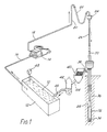
- FIG. 1 of the accompanying Drawings shows the main components of the mud circulation equipment.
- the mud (10) is contained in a mud pit (12), called the active tank.
- a pump (14) draws up the mud from the pit through a pipe (16), and forces the mud through the discharge line (18), the stand pipe (20), the rotary hose (22) and the swivel (24).
- the mud then flows into the kelly (26) and down the borehole (28) in the drill pipe (30) and the drill collars (32).
- the mud reaches the bottom of the hole at the drill bit (34), and then flows up to the surface in the annulus (36) and in the mud return line (38).
- Shale shaker underflow mud is fed (via line 44) to additional solids control equipment (42), which may include a combination of devices such as a degasser, hydrocyclone desander/desilter, and/or decanting centrifuges.
- Solids control equipment underflow mud is fed (via line 46) to the active tank 12. Batches of freshly prepared mud and quantities of mud products are added to the active tank mud 10 during drilling.
- the batches of freshly prepared mud replace (i) volumes of mud taken up by an increasing volume of borehole 28, (ii) volumes of mud lost on solids removal by the solids control equipment 40 and 42, and (iii) volumes of mud which may be discarded due to a loss of desired properties (such as mud containing large quantities of fine drilled solids which cannot be removed by the solids control equipment but which would slow down drilling if recirculated into the borehole).
- Quantities of mud products are added to mud in the active tank so as to maintain their concentration specified in the original mud formulation.
- Such a technique may also be applied to an analysis of solids removed by the solids control equipment, but here it can be highly inaccurate; for example, an apparently increasing high gravity fraction in solids removed by a hydrocyclone may in fact be caused by an increasing average formation density due a change of drilled lithology. Further inaccuracies may be introduced as a result of varying concentrations of salt components originating from added mud products or, more particularly, when drilling through evaporite sequences.
- XRD is normally capable of quantifying minerals within a relative accuracy of ⁇ 5-10%, however, crystallinity differences between standards and unknown samples, and the presence of amorphous material (for example, organic material such as kerogen from the formation, or contaminant polymeric mud products), may introduce considerable systematic error.
- amorphous material for example, organic material such as kerogen from the formation, or contaminant polymeric mud products
- the method described in the latter patent involves: (i) a cleaning procedure to remove components other than the analyte mineral components; (ii) the reduction of sample particle size to an average of one micron, with no particles larger than two microns; (iii) the dilution of the crushed sample with potassium bromide (KBr); (iv) the production of a pressed disc from which a transmission FTIR spectrum is obtained; and (v) a comparison of the sample spectrum with transmission spectra for pure minerals in order to obtain a quantitative mineralogical analysis.
- any hydrocarbon in the core sample is removed by techniques such as toluene solvent extraction or CO2 cleaning prior to the mineralogical analysis; the Patent does not describe a method to determine the hydrocarbon content or the content of any component other than the mineral components in a core or cuttings sample.
- the article proposes a method for the determination of minerals in rock samples which involves: (i) pregrinding the mineral to 325 mesh; (ii) dispersion of the ground mineral in KBr; (iii) the production of a pressed disc from which a transmission FTIR spectrum is obtained; and (iv) a comparison of the sample spectrum with transmission spectra for pure minerals in order to obtain a quantitative mineralogical analysis.
- the invention proposes, therefore, that some or all of the solids removed from a drilling mud be both qualitatively an quantitatively determined by the mid-range IR spectroscopic analysis of a sample thereof, this method involving: preparing the sample in dry powder form; analysing the powder in an IR spectrometer, to obtain an IR spectrum; and determining therefrom a value characteristic of the concentration in the sample of one or more of its constituents. It will be seen, then, that one object of the invention is to provide a method of determining the concentration of mud product components and mineral components in the solids samples.
- a further object is to enable the use of the thus-measured concentrations in conjunction with corresponding data for certain mud streams (as described in our aforementioned copending Application) so as to assess: - the accountability of mud products used to prepare a specified mud formulation, and of mud products used to maintain the said mud formulation during drilling; - the efficiency of drilled cuttings/solids removal by solids control equipment; - the efficiency of certain mud products (such as encapsulating polymers) which may be specifically added to the mud formulation in order to improve the removal of certain drilled solids (such as water-sensitive shales); - the stability of a drilled hole interval as indicated by an assessment of its gauge; and - the mixing properties of certain surface mud holding tanks (such as the active tank).
- the invention provides a method of quantitative analysis of drilled cuttings/solids samples obtained in the course of the drilling of a borehole using a "mud" drilling fluid, in which method the solids removed by one or more of the solids control devices are representatively sampled and the sample is analysed, the method comprising the following steps: - the sample is homogenised; - a known weight of the homogenised sample is dried to constant weight, and the weight fraction of solids, W (s) in the sample is determined; - the dried solids are crushed and homogenised to form a powder suitable for quantitative infrared analysis, and the powder is analysed in a mid-range infrared spectrometer in order to obtain an infrared spectrum; and - knowing the solids weight fraction, a value representative of the quantity of at least one of the mud product components and/or at least one of the mineral components in the sample is determined from the spectrum.
- the material being analysed according to the method of the invention is a combination of the solids removed from the mud - that is, the cuttings, etc - and the solids retained in the mud - thus, the mud products - and carried by the removed solids.
- the technique of analysis of the invention involves no separation process of these substances, and allows the quantitative analysis of them all - thus, including products such as polymer(s) present in the drilling fluid.
- the proposed method also has the advantage of determining the quantities of the components by one analysis only: the polymer(s) and the other mud products such as added mud solids (eg barite, bentonite) and "fines" (eg carbonates, quartz) can be quantified simultaneously with the minerals etc in the removed cuttings.
- the mud product components are mainly polymer(s), bentonite clay and barite, and possibly oil.
- the various mineral components include quartz, feldspars, clay minerals (such as montomorillonite, illite and kaolinite, which can be detected individually), carbonates (such as dolomite and calcite) and sulphates (such as gypsum and anhydrite).
- mid-range infrared spectroscopy that is, spectroscopy employing infrared generally in the middle of the range of wavelengths recognised as infrared.
- mid-range infrared is generally defined as infrared being a wavelength in the range 2,500 to 25,000 nanometres (a wavelength range of from 4,000 to 400 cm ⁇ 1).
- near-range infrared is generally from 800 to 3,000 nanometres, while far-range infrared is generally beyond 25,000 nanometres and up to the microwave region.
- the spectrum is preferably obtained by Fourier transform infrared (FTIR) spectroscopy, and by a diffuse reflectance technique.
- FTIR Fourier transform infrared
- IR spectroscopy The principles of IR spectroscopy are well known, and in general the technique requires the sample being analysed to be "mounted" on or within an IR-transparent carrier.
- the sample may be pasted with NUJOL (or some similar paste) and supported between two rocksalt (sodium chloride) plates, or it is incorporated into a salt powder, and pressed into a small lozenge, or pellet.
- the preparation of the powder for infrared analysis includes the mixing of a known weight of dried drilling fluid solids with a halide salt to form a mixture, grinding the mixture until the particle size of the solids is no more then 2 microns to obtain the desired powder, and then pressing the powder into a pellet.
- the halide salt is preferably bromide or sodium chloride.
- conventional reflectance spectroscopy which technique is usable with advantage in the method of this invention, the sample is simply incorporated in a salt powder (but not, of course, pelleted).
- the diffuse reflectance technique is particularly preferred for the present invention for the following reasons: - It is a more rapid technique, and avoids the manufacture of halide pellets. - Overtone and weaker bands in the infrared spectrum are often more prominent in diffuse reflectance than in direct transmission mode; such bands may be essential for quantification of the lower concentrations of mud products (such as polymers) and mineral components (such as accessory minerals) in solids samples. - Direct transmission techniques give rise to intense absorption bands in the infrared spectrum which may not be suitable for use in linear quantitative techniques. - Larger sub-sample weights are used in the diffuse reflectance technique - typically a 0.4g sub-sample representing the primary sample may be used for an evaluation of solids removed by a solids control device. In comparison, a typical 0.004g sub-sample as used in direct transmission techniques may not adequately represent the primary sample composition. Also, the analytical problems of obtaining an accurate sub-sample weight are reduced by using a diffuse reflectance technique.
- the interpretation of the concentration of the products is preferably achieved by first obtaining the infrared spectra of known multi-component compositions of the drilling solids, and by generating a calibration model from those spectra.
- the technique of analysis of the invention involves no separation process (eg filtration and/or centrifugation) of the mud product components or the mineral components from the drilled cuttings/solids sample. More precisely, the invention relates to a method of quantitative analysis of "whole" drilled cuttings/solids samples which contain mud products, drilled minerals, dissolved salts and base fluid.
- the proposed method has the advantage that mud product and mineral components are determined simultaneously (by one analysis only). In order to ascertain whether erosion of the open wellbore has occurred a quantitative mineralogical analysis of the "whole" drilled cuttings sample may be compared to a corresponding analysis of its "cavings" fraction.
- An evaluation of mud product and mineral components in drilled cuttings/solids and various mud streams flowing through the mud circulation equipment may be used to compile a number of mass balances each of which is designed to assess various aspects of a mud engineering service during drilling.
- Five such mass balances have been identified in Table 1; each mass balance requires an evaluation of one or more mud products and/or mineral components in the indicated input and output streams.
- Table 1 An evaluation of mass balance A is described below.
- the input mass of return mud dumped onto a shale shaker per unit time is equal to the output mass of drilled cuttings plus the mass of shaker underflow mud generated per unit time.
- the unit of time across which a representative mass balance may be compiled will depend on working conditions during drilling.
- the mass of drilled material generated per unit time, A will depend on the rate of penetration (ROP), the hole diameter (hd) and the average formation density ( ⁇ (f) ):
- the weight fraction of drilled material in return mud loaded onto the shaleshaker, B will depend on A, the return mud flow rate, Q (rm) and the return mud density, ⁇ (rm) :
- a representative shale shaker mass balance may be obtained by evaluating input and output material over a five minute period. Five minutes of drilling deepens the wellbore by 0.762m and generates 150.48 kg of drilled material which is carried to the surface in 0.6 m3 (7200 kg) of return mud. Assuming that the shale shaker removes (i) 60 wt.% of the drilled material and (ii) one litre of mud per one litre of formation drilled, then the 7200 kg batch of input return mud will generate 159.74 kg of output "wet" drilled cuttings (containing 90.29 kg drilled material and 69.46 kg return mud) and 7040.26 kg of output shaker underflow mud.
- Representative primary samples of the input return mud stream and output shaker underflow stream may be conveniently obtained by taking a one litre sample from well mixed "averaging" tanks (as proposed in the patent specification of British Patent Application No: 8926778.5).
- a one litre primary sample of return mud taken from a well mixed averaging tank containing a 0.6 m3 mud volume in steady state represents 0.6 m3 of input return mud.
- Representative primary samples of drilled cuttings generated from the 0.6 m3 input batch of return mud may be conveniently sampled by a device such as a mechanical sample receiver which collects "oversize" material falling off 5% of the shaker screen width; the sample receiver moves across the full width of the shaker at an optimum frequency during the sampling period in order to ensure that the primary sample collected represents the entire output stream.
- a mechanical sample receiver will take a 5% cut of the entire output stream - ie a 0.0046 m3 (7.96 kg) primary sample is taken from the total of 0.0926 m3 (159.46 kg) of "wet" drilled cuttings material generated from the 0.6 m3 (7200 kg) input batch of return mud.
- the pre-tared sample receiver is reweighed after collection of the primary sample; the primary sample weight, M (ps) is used to calculate the weight of the entire output stream, C using the following relationship:
- the primary sample is thoroughly homogenised using a high speed blender prior to taking a secondary sample for subsequent analysis.
- a high speed blender prior to taking a secondary sample for subsequent analysis.
- the secondary sample is analysed as follows:
- a known sample volume is weighed in order to determine sample density; a known sample weight is then dried to constant weight in order to determine the weight fraction of solids, W (s) ; due corrections for the known weight of deionised water added in order to homogenise the primary sample and the weight of residual salts in the dried solids residue are taken into account.
- Procedures for the determination of mud product and/or mineral component(s) in the dried solids samples are given hereinbefore.
- a typical shale shaker mass balance is shown in Table 2. Such a mass balance may be compiled on a regular basis so as to assess drilled solids removal efficiency and to account for losses of mud products during a mud engineering service.
- the efficiency of solids removal by the shale shaker(s) and other solids control devices depends on the particle size distribution of drilled solids contained in the return mud; regular mass balancing may be used to optimise drilled solids removal efficiency according to drilled lithology.
- Field data has indicated that approximately one litre of return mud is removed by a shale shaker per one litre of formation drilled; the mass balance given in Table 2 assumes such a mud removal, and further indicates that, when using a typical weighted mud formulation, 20 kg of barite is removed per m3 of return mud loaded onto the shale shaker (at this rate, over a 24 hour period nearly six metric tons of barite would be removed).
- the dried mud solids and polymers are prepared for quantification using infrared spectroscopy. Firstly, there is taken an accurate weight of dried mud solids and polymers. This may be used as it is or it may be mixed with a halide salt (such as potassium bromide or sodium chloride), the chosen concentration of mud solids being about 5 weight percent (the halide salt decreases the difference of refractive indexes between the air and the mixture, and therefore decreases the loss of infrared radiation by reflection on the solids, but the dilution may result in trace components becoming undetectable).
- a halide salt such as potassium bromide or sodium chloride
- the whole is ground in a ball mill or pestle and mortar, preferably made of agate to minimise contamination from the material of the mill during grinding, to form a powder the particle size of which is below 2 microns, ie the smallest wavelength in the mid-infrared range.
- a particle size can be achieved within a few minutes using a small grinding mill - eg a Wig-L-Bug microniser manufactured by Crescent Dental Manufacturing Company of the USA.
- the powdered sample is placed in a diffuse reflectance cell, and the spectrum collected by an infrared spectrometer, preferably a Fourier transform infrared spectrometer.
- the equivalent transmission spectrum can be obtained by performing the Kubelka-Munk transform on the raw reflective spectrum data. This transform is described for example in the book Reference Spectroscopy by G Kortoem, a Springer-Verlag publication, 1969. Such a transform is convenient only but not essential for the quantification; the diffuse reflectance spectrum corresponds to infrared radiation emitted by the solids molecules following their absorption of the radiation emitted by the infrared source of the spectrometer.
- the diffuse reflectance spectrum of the recovered mud solids can be interpreted quantitatively using a number of techniques, including the Beer-Lambert law.
- this law there is a linear relationship between the diffuse reflectance - or the absorbance - of a product and its concentration at a single, fixed frequency, and the spectrum of a mixture can be analysed in terms of characteristic value of frequency for each of its individual components.
- a multivariate statistical technique which uses the absorbance at a number of wavelengths, is preferred since a mixture of several components often results in marked deviations in the Beer-Lambert law.
- the spectrum of a mixture can be considered to be a linear combination of those of the pure components, and calibrations must be developed from the spectra of such mixtures.
- Multivariate statistical techniques can be used to generate a calibration model of the dried mud solids; the model essentially consists of a regression (or partial regression) of the spectral and concentration data sets of standards of accurately known compositions.
- Examples of such multivariate techniques are multiple linear regression, principal components analysis, and partial least squares path modelling. This last technique is preferred, and is described in the book Multivariate Calibration by H Martens and T Naes, a Wiley publication, 1989.
- An example of a computer programme to perform the partial least squares regression is the well-known UNSCRAMBLER software, developed at the Norwegian Food Research Institute and described in the journal Chemometrics and Intelligent Laboratory Systems, Volume 2, pages 239-243, 1987.
- Example 1 Quantification of the various components in removed solids and a water-based mud
- a typical weighted mud formulation containing bentonite, low viscosity carboxymethyl cellulose (CMC-LV), xanthan gum (XC) and barite was used to drill through formations of dolomitic limestone and gypsum.
- Average concentrations of each of the four mud products in the mud formulation are given below: Bentonite 36 g/l CMC-LV 10 g/l XC 1 g/l Barite 180 g/l
- Drilled cuttings/solids generated by the solids control equipment contain each of the four mud product components, as well as four formation mineral components - dolomite, calcite, gypsum and quartz.
- the composition of the calibration standards is dominated by a weight fraction of mineral components between 0.7835 and 0.9342, the weight fractions of mud product components constitute between 0.0658 and 0.2165 of the total composition.
- the xanthan gum (XC) component originally present within a concentration range of 0.8 - 4.2 g/l in the original mud formulation, constitutes a low weight fraction range of 0.0005 - 0.0032 in the calibration standards.
- Characteristic overtone peaks due to the dolomite component are well developed in this diffuse reflectance spectrum; such overtones are weakly developed in transmission spectra for the same calibration standard. Strongly developed overtone peaks in diffuse reflectance spectra for multicomponent mixtures may be essential for the quantification of trace components.
- Figures 3a, 3b, 3c and 3d show the calibration curves used to quantify the mud product components (bentonite, CMC-LV, XC and barite, respectively). Corresponding curves used for the quantification of dolomite, calcite, gypsum and quartz are shown in Figures 4a, 4b, 4c and 4d.
- results for a series of six test drilled cuttings/solids samples are given in Table 3.
- the samples (1 to 6) represent drilled cuttings samples generated by drilling across a lithological boundary between an upper dolomite limestone (containing dolomite with some quartz) and a lower gypsum deposit (containing gypsum and quartz).
- the four mud product components (bentonite, CMC-LV, XC and barite) are quantified in the test samples within average relative accuracies of ⁇ 10%, ⁇ 13%, ⁇ 30% and ⁇ 4% respectively.
- the relatively low accuracy of predicting XC concentrations in the test samples is attributed to a low absolute XC concentration range which may be nearing the lower limits for spectral deconvolution.
- the accuracy of predicting bentonite, CMC-LV and barite concentrations in the test samples is sufficient to justify a routine analysis of cuttings/solids removed by the solids control equipment in order that the three mud products are regularly accurately accounted for during the mud engineering service.
- the four mineral components (dolomite, calcite, gypsum and quartz) are quantified in the test samples within average relative accuracies of ⁇ 3%, ⁇ 11%, ⁇ 12% and ⁇ 7% respectively.
- the relationship between relative accuracy for prediction of gypsum concentration and absolute gypsum concentration is shown in Figure 5; clearly, the relative inaccuracy of predicting a gypsum concentration below approximately 3% must be taken into account when using such analyses to determine the efficiency of removing drilled solids generated at the interface between the upper dolomitic limestone and the lower gypsum deposit.
- Example 2 Quantification of the various components in removed solids and a water-based mud containing diesel oil
- a typical weighted mud formulation containing bentonite, polyanionic cellulose (PAC), ferrochrome lignosulphonate (FCL), lignite, an asphaltene product, barite and diesel oil was used to drill through an upper formation "A” (containing calcite, quartz, and kaolinite) and a lower formation "B" (containing dolomite and anhydrite).
- Average concentrations of each of the seven mud products in the mud formulation are given below: Bentonite 50 g/l PAC 5 g/l FCL 15 g/l Lignite 15 g/l Asphaltene 15 g/l Barite 180 g/l Diesel oil 50 ml/l
- FIGS. 6a, 6b, 6c and 6d show the calibration curves used to quantify PAC, FCL, Asphaltene and Diesel oil; corresponding curves for calcite, quartz and kaolinite are shown in Figures 7a, 7b and 7c.
- the quantification of diesel oil in a return mud and/or drilled cuttings/solid sample deserves special note.
- Sample preparation involves drying to constant weight so as to determine the weight fraction of solids, W (s) .
- a drying temperature of 160 o C may be used to keep drying time to a minimum.
- a large fraction of the diesel oil is volatile.
- the volatile fraction of a particular diesel oil will be a constant for a set drying temperature. Therefore, the concentration variance for diesel oil in calibration standards will be maintained through such a drying stage.
- FTIR spectra will show absorbance peaks due to the non- volatile fraction; such spectral information is well correlated with concentration variance for a set of calibration standards as shown in Figure 6d.
- the determination of diesel oil in an unknown sample involves a measurement using the calibration curve and a correction for the volatile fraction.
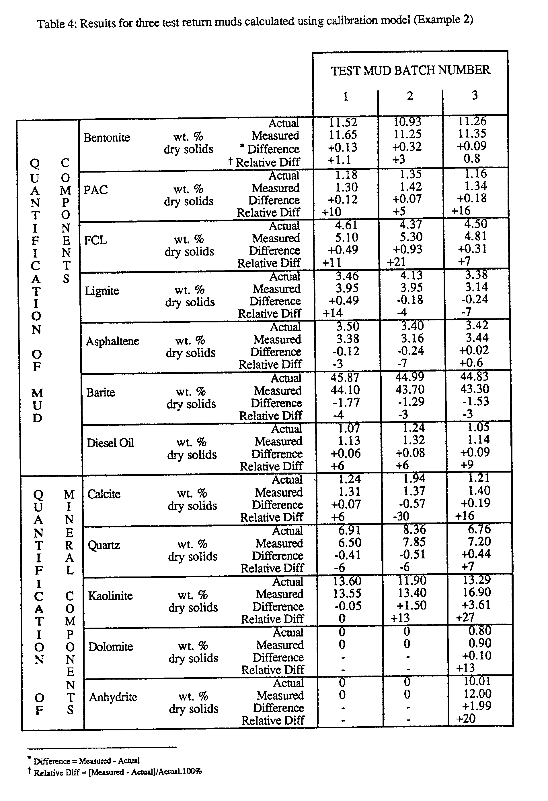
- Test mud samples 1 and 2 contain drilled material originating from the upper formation "A”, whilst test mud sample 3 also contains drilled material from formation "B”. Over 80% lof the data lies within a relative accuracy of ⁇ 10%. Drilled minerals are satisfactorily quantified together with a simultaneous analysis of the seven mud components.
Landscapes
- Life Sciences & Earth Sciences (AREA)
- Mining & Mineral Resources (AREA)
- Engineering & Computer Science (AREA)
- Physics & Mathematics (AREA)
- Chemical & Material Sciences (AREA)
- Geology (AREA)
- Dispersion Chemistry (AREA)
- Biochemistry (AREA)
- Geochemistry & Mineralogy (AREA)
- Fluid Mechanics (AREA)
- Environmental & Geological Engineering (AREA)
- Health & Medical Sciences (AREA)
- Analytical Chemistry (AREA)
- General Life Sciences & Earth Sciences (AREA)
- General Health & Medical Sciences (AREA)
- General Physics & Mathematics (AREA)
- Immunology (AREA)
- Pathology (AREA)
- Investigating Or Analysing Materials By Optical Means (AREA)
- Sampling And Sample Adjustment (AREA)
Abstract
Description
- This invention concerns the analysis of drilling solids, and relates in particular to a method of quantitative analysis of the solids in a drilling fluid (usually called "mud") used to drill a well.
- In the rotary drilling of wells, such as hydrocarbon wells, a drilling fluid or mud is continuously circulated from the surface down to the bottom of the hole being drilled and back to the surface again. The mud has several functions, one of them being to transport cuttings drilled by the drill bit up to the surface where they are separated from the mud, while another is to impose an hydrostatic pressure on the walls of the borehole so as to avoid a collapse of the borehole and an influx of gas or liquid from the formations being drilled. The characteristics of the mud are therefore important to monitor and to keep within certain limits. For instance, the viscosity of the mud is an important characteristic since it contributes to the cuttings transport capability of the mud, and clays, such as bentonite clay, are added to the mud so as to keep the drilled cuttings in suspension as they move up the hole (the clay also sheathes the wall of the hole; this thin layer of clay, called filter cake, reduces the loss of mud to permeable formations caused by filtration). The density of the mud is another significant factor. It must be large enough so as to exert a certain hydrostatic pressure on the formation, but not too large to fracture these formations. Weighting materials, barite for example, are added to the mud to make it exert as much pressure as needed to contain the formation pressures. These are examples of the numerous chemicals available to give the mud the exact properties it needs to make it as easy as possible to drill the hole.
- Drilling muds are of two main types, distinguished by whether water or oil is used as the continuous phase. Water-based muds are typically suspensions of bentonite clay, to which further heavier minerals (usually barite), polymers and surfactants are added to optimise the rheology and other physical properties for a particular job. Oil-base drilling fluids, on the other hand, are most commonly water-in-oil emulsions where micron-sized brine droplets, stabilised by emulsifier, are dispersed in a mineral oil, along with organophilic clays, weighting minerals, wetting agents and oil-soluble viscosifiers.
- In addition to the products deliberately added in the drilling mud for specific purposes, other materials coming from the formation being drilled and/or from the borehole wall can be present in the mud. These products are mainly in the form of minute particles of solids (an average diameter being about 50-100 microns), and are usually called "fines". Examples of "fines" are silica (quartz), carbonates and dispersed clay particles. Hereinafter the term "mud products" is used to designate both the mud additives and the "fines".
- As noted above, one of the mud's functions is to transport the drilled cuttings up to the surface. The cuttings are then separated off using "solids control" equipment, and the mud, possibly after the addition of one or more materials to restore its make-up and properties, is re-used.
- A number of solids control devices are used to remove drilled cuttings and solids from the return mud. The cuttings, which typically have a particle size between several millimetres and about 175 microns, are filtered from the return mud using vibrating screens known as "shale shakers". Sand-sized drilled solids (which have particle sizes in excess of about 75 microns) and silt-sized drilled solids (which have particle sizes in excess of about 2 microns) are removed by hydrocyclone desanders and hydrocyclone desilters respectively. Under certain circumstances, decanting centrifuges may also be used to remove fine drilled solids which have particle sizes less than 20 microns. A typical set-up for a solids control system is seen in Figure 1 of the accompanying Drawings, which shows the main components of the mud circulation equipment. The mud (10) is contained in a mud pit (12), called the active tank. A pump (14) draws up the mud from the pit through a pipe (16), and forces the mud through the discharge line (18), the stand pipe (20), the rotary hose (22) and the swivel (24). The mud then flows into the kelly (26) and down the borehole (28) in the drill pipe (30) and the drill collars (32). The mud reaches the bottom of the hole at the drill bit (34), and then flows up to the surface in the annulus (36) and in the mud return line (38). The return mud, laden with drilled material, then falls over a vibrating screen-like device (40), called a shale shaker. Shale shaker underflow mud is fed (via line 44) to additional solids control equipment (42), which may include a combination of devices such as a degasser, hydrocyclone desander/desilter, and/or decanting centrifuges. Solids control equipment underflow mud is fed (via line 46) to the
active tank 12. Batches of freshly prepared mud and quantities of mud products are added to theactive tank mud 10 during drilling. The batches of freshly prepared mud replace (i) volumes of mud taken up by an increasing volume ofborehole 28, (ii) volumes of mud lost on solids removal by thesolids control equipment - It will be readily apparent that for a correct understanding of the drilling process it is necessary to have results from accurate analysis not only of the mud but also of the solids separated therefrom by the various stages of the solids control equipment. So far as the latter are concerned, it should be borne in mind that, whilst the composition of the removed drilled cuttings and solids is typically dominated by mineral components originating from the rock formations being drilled, there will also be present considerable quantities of added mud product components coming from the mud formulation.
- To give some idea of the scale of the problem it should be noted that typical field data indicates that approximately one litre of mud may be removed by the solids control equipment for every one litre of formation drilled. Therefore, in order to maintain a constant volume of mud in surface holding tanks, the mud engineer needs in principle to add two litres of fresh mud volume for every one litre of formation drilled (in practice, additional volumes of fresh mud may be added to replace return mud which is discarded due to its non-optimum properties). Current mud engineering practices do not attempt to evaluate and account for losses of mud products in solids removed by the solids control equipment or in discarded mud.
- Investigations have also indicated that for every volume of dried cuttings produced by a typical shale shaker configuration an equal volume of mud is removed. Such a degree of "contamination" of cuttings by a typical barite-weighted mud formulation (with mud density, ρ(m) = 1.2 kg/l and average mud solids density,
ρ (ms) = 4.1 kg/l) used to drill a typical formation (with average formation density,ρ (f) = 2.6 kg/l) produces dried cuttings solids which contain 89.8 weight percent formation mineral components and 10.2 weight percent mud product components. And it is well known that considerable quantities of the coarser fractions of API-grade barite are present in solids removed by the hydrocyclones. - A variety of techniques are employed to determine the nature and amounts of the numerous components in the mud and the removed solids, but not all are equally satisfactory. Thus: the current field technique used to determine the solids content of a mud sample involves the use of a retort to dry the sample to constant weight. This technique measures percentage solids by volume and by weight, allowing an average solids density to be calculated; the latter data is used to calculate a percentage "high gravity solids" (assuming a high gravity solids density, ρ(hgs) = 4.3 kg/l) and a percentage of "low gravity solids" (assuming a low gravity solids density ρ(lgs) = 2.5 kg/l). Such a technique may also be applied to an analysis of solids removed by the solids control equipment, but here it can be highly inaccurate; for example, an apparently increasing high gravity fraction in solids removed by a hydrocyclone may in fact be caused by an increasing average formation density due a change of drilled lithology. Further inaccuracies may be introduced as a result of varying concentrations of salt components originating from added mud products or, more particularly, when drilling through evaporite sequences.
- The published and presently used methods for the analysis of drilled cuttings have focussed on a qualitative and/or quantitative assessment of mineral components in order to evaluate the composition of drilled lithologies. During a conventional mud logging operation, cuttings samples may be taken from the shale shaker after drilling intervals of 20-50 feet. Each cuttings sample is evaluated by a geologist who carries out a number of qualitative tests and provides a lithological description for the mud log. The technique most widely used in the industry for a quantitative determination of the mineral components in drilled cuttings and core samples is x-ray diffraction analysis (XRD). XRD is normally capable of quantifying minerals within a relative accuracy of ±5-10%, however, crystallinity differences between standards and unknown samples, and the presence of amorphous material (for example, organic material such as kerogen from the formation, or contaminant polymeric mud products), may introduce considerable systematic error.
- Another method proposed for the quantitative analysis of mineral components in core samples and drilled cuttings (and in core samples) is the subject of two recent US Patents (4,608,859 and 4,839,516), namely infrared spectroscopy (particularly Fourier-transform infrared spectroscopy, FTIR) in the wave number range 5,000 to 400 cm⁻¹ (2,000 to 25,000 nanometres), corresponding to mid-range infrared. The method described in the latter patent involves: (i) a cleaning procedure to remove components other than the analyte mineral components; (ii) the reduction of sample particle size to an average of one micron, with no particles larger than two microns; (iii) the dilution of the crushed sample with potassium bromide (KBr); (iv) the production of a pressed disc from which a transmission FTIR spectrum is obtained; and (v) a comparison of the sample spectrum with transmission spectra for pure minerals in order to obtain a quantitative mineralogical analysis. It is important to note that the method described states that any hydrocarbon in the core sample is removed by techniques such as toluene solvent extraction or CO₂ cleaning prior to the mineralogical analysis; the Patent does not describe a method to determine the hydrocarbon content or the content of any component other than the mineral components in a core or cuttings sample.
- The use of FTIR spectroscopy to determine mineral composition of rock samples, such as shale samples, has also been described in the article entitled The quantitative analysis of complex multicomponent mixtures by FT-IR; the analysis of minerals and of interacting blends by James M. Brown and James J. Elliott, published in the book Chemical, Biological and Industrial Applications of Infrared Spectroscopy, a Wiley-Interscience publication, 1985. The article proposes a method for the determination of minerals in rock samples which involves: (i) pregrinding the mineral to 325 mesh; (ii) dispersion of the ground mineral in KBr; (iii) the production of a pressed disc from which a transmission FTIR spectrum is obtained; and (iv) a comparison of the sample spectrum with transmission spectra for pure minerals in order to obtain a quantitative mineralogical analysis.
- It is important to note that the above mentioned US Patents and the Brown and Elliott article propose methods for the quantitative analysis of mineral components in cleaned drilled cuttings, and in core and rock samples; there is no suggestion that the method might be of value for the quantitative analysis of mud products in drilled cuttings samples.
- An alternative infrared analytical technique is the subject of GB Patent Specification No: 2,217,838 which is mainly concerned with the specific determination of oils and other materials, for which it can be advantageous to use the overtone and combination bands of the fundamental O-H, C-H and N-H stretching vibrations since they are generally more sensitive to chemical composition than the fundamental bands. However, the overtone and combination bands of the fundamental vibration frequencies of bands containing heavier atoms, commonly found in minerals (eg S-O, Si-O) and polymers (eg C-N, C-O) are found in the mid-infrared and therefore are not revealed. By opposition, these heavier materials are particularly well revealed by the diffuse reflectance technique described herein.
- It will be evident that accurate evaluation of mud products in solids removed by the solids control equipment, together with a corresponding evaluation for mud entering and exiting the equipment, provides information with which to compile a mass balance for the mud components on a regular basis. Such information may be used to account for the mud products during a mud engineering service. Regular mass balances for each mud product provide useful information with which both to evaluate and account for their losses in solids removed by the solids control equipment and to monitor the performance of mud products such as an encapsulating polymer. However, none of the analytical techniques presently in use allow this to be effected, for none accurately analyse the removed solids because they either ignore or incorrectly assess the mud products carried by these removed solids. The "contamination" of the cuttings by barite has already been alluded to, but there are a number of other possibilities that give rise to particular concern. Thus, this type of problem may be aggravated by the very nature of the mud products. For instance, certain polymeric mud products - eg partially hydrolysed polyacrylamide (PHPA) - are specifically added to the mud formulation in order to stabilise cuttings generated by particularly water-sensitive formations such as shales; they adsorb on and encapsulate water-sensitive cuttings, allowing the drilled material to be more efficiently removed by the solids control equipment. At present, there are no adequate analytical techniques to monitor the concentration of such polymeric products in removed solids.
- In addition, a major area of environmental concern is the retention of oil on drilled cuttings either when using an oil-based mud formulation or when lubricant oils are added to a water-based mud formulation. At present, there are no adequate analytical techniques to determine the oil content of solids removed by the solids control equipment, but one is required in order to provide the necessary information for an accurate accounting for the base or lubricant oil (and to enable an assessment of the efficiency of the processes used to recover the oil from solids removed by the solids control equipment).
- In our co-pending GB Application No: 9011527 there is described a quantitative analysis method for mud products, which method uses mid-range infrared spectroscopy, most preferably Fourier-transform infrared spectroscopy carried out in reflectance mode on a raw, undiluted sample of dried and powdered mud solids. It has now rather surprisingly been found that essentially the same technique may be applied to the removed mud solids - that is to say, to the drilled cuttings and other removed solid materials together with any mud products carried thereby - to provide an efficient quantitative analysis of the removed solids with respect to the nature and content both of the formation-derived materials and of the mud-derived materials. The invention proposes, therefore, that some or all of the solids removed from a drilling mud be both qualitatively an quantitatively determined by the mid-range IR spectroscopic analysis of a sample thereof, this method involving: preparing the sample in dry powder form; analysing the powder in an IR spectrometer, to obtain an IR spectrum; and determining therefrom a value characteristic of the concentration in the sample of one or more of its constituents. It will be seen, then, that one object of the invention is to provide a method of determining the concentration of mud product components and mineral components in the solids samples. A further object is to enable the use of the thus-measured concentrations in conjunction with corresponding data for certain mud streams (as described in our aforementioned copending Application) so as to assess:
- the accountability of mud products used to prepare a specified mud formulation, and of mud products used to maintain the said mud formulation during drilling;
- the efficiency of drilled cuttings/solids removal by solids control equipment;
- the efficiency of certain mud products (such as encapsulating polymers) which may be specifically added to the mud formulation in order to improve the removal of certain drilled solids (such as water-sensitive shales);
- the stability of a drilled hole interval as indicated by an assessment of its gauge; and
- the mixing properties of certain surface mud holding tanks (such as the active tank). - Evaluation procedures required in order to carry out the above assessments through a compilation of several mass balances are described in detail hereinafter.
- Accordingly, the invention provides a method of quantitative analysis of drilled cuttings/solids samples obtained in the course of the drilling of a borehole using a "mud" drilling fluid, in which method the solids removed by one or more of the solids control devices are representatively sampled and the sample is analysed, the method comprising the following steps:
- the sample is homogenised;
- a known weight of the homogenised sample is dried to constant weight, and the weight fraction of solids, W(s) in the sample is determined;
- the dried solids are crushed and homogenised to form a powder suitable for quantitative infrared analysis, and the powder is analysed in a mid-range infrared spectrometer in order to obtain an infrared spectrum; and
- knowing the solids weight fraction, a value representative of the quantity of at least one of the mud product components and/or at least one of the mineral components in the sample is determined from the spectrum. - Where the selected component was originally in a liquid state, a preliminary determination of the homogenised sample's density, ρ(s), allows the subsequent determination from the spectrum of that component's concentration.
- The material being analysed according to the method of the invention is a combination of the solids removed from the mud - that is, the cuttings, etc - and the solids retained in the mud - thus, the mud products - and carried by the removed solids. The technique of analysis of the invention involves no separation process of these substances, and allows the quantitative analysis of them all - thus, including products such as polymer(s) present in the drilling fluid. The proposed method also has the advantage of determining the quantities of the components by one analysis only: the polymer(s) and the other mud products such as added mud solids (eg barite, bentonite) and "fines" (eg carbonates, quartz) can be quantified simultaneously with the minerals etc in the removed cuttings. The mud product components are mainly polymer(s), bentonite clay and barite, and possibly oil. The various mineral components include quartz, feldspars, clay minerals (such as montomorillonite, illite and kaolinite, which can be detected individually), carbonates (such as dolomite and calcite) and sulphates (such as gypsum and anhydrite).
- The invention used mid-range infrared spectroscopy - that is, spectroscopy employing infrared generally in the middle of the range of wavelengths recognised as infrared. For the purpose of this invention mid-range infrared is generally defined as infrared being a wavelength in the range 2,500 to 25,000 nanometres (a wavelength range of from 4,000 to 400 cm⁻¹). By contrast, near-range infrared is generally from 800 to 3,000 nanometres, while far-range infrared is generally beyond 25,000 nanometres and up to the microwave region.
- The spectrum is preferably obtained by Fourier transform infrared (FTIR) spectroscopy, and by a diffuse reflectance technique.
- The principles of IR spectroscopy are well known, and in general the technique requires the sample being analysed to be "mounted" on or within an IR-transparent carrier. Thus, for example, in conventional transmission spectroscopy the sample may be pasted with NUJOL (or some similar paste) and supported between two rocksalt (sodium chloride) plates, or it is incorporated into a salt powder, and pressed into a small lozenge, or pellet. In this latter technique the preparation of the powder for infrared analysis includes the mixing of a known weight of dried drilling fluid solids with a halide salt to form a mixture, grinding the mixture until the particle size of the solids is no more then 2 microns to obtain the desired powder, and then pressing the powder into a pellet. The halide salt is preferably bromide or sodium chloride. In conventional reflectance spectroscopy, which technique is usable with advantage in the method of this invention, the sample is simply incorporated in a salt powder (but not, of course, pelleted).
- The diffuse reflectance technique is particularly preferred for the present invention for the following reasons:
- It is a more rapid technique, and avoids the manufacture of halide pellets.
- Overtone and weaker bands in the infrared spectrum are often more prominent in diffuse reflectance than in direct transmission mode; such bands may be essential for quantification of the lower concentrations of mud products (such as polymers) and mineral components (such as accessory minerals) in solids samples.
- Direct transmission techniques give rise to intense absorption bands in the infrared spectrum which may not be suitable for use in linear quantitative techniques.
- Larger sub-sample weights are used in the diffuse reflectance technique - typically a 0.4g sub-sample representing the primary sample may be used for an evaluation of solids removed by a solids control device. In comparison, a typical 0.004g sub-sample as used in direct transmission techniques may not adequately represent the primary sample composition. Also, the analytical problems of obtaining an accurate sub-sample weight are reduced by using a diffuse reflectance technique. - The last two mentioned reasons may prevent a transmission technique from being used to evaluate mud products and minerals in solids removed by the solids control equipment. They may also, however, require a significant modification in the reflectanct method itself, for while a reflectance spectrum obtained from a salt/sample powder admixture can be perfectly satisfactory, in a reflectance method of this type a high proportion of the returned IR energy has in fact undergone transmission through the surface "layers" of the sample powder, and recent work has shown that, because of the relatively similar refractive indices of the materials involved, one result of effectively incorporating the sample solids within the salt is for refractive effects to mask the weaker signals produced by some of the less plentiful sample components. It has now been found that a rather different - and in some ways markedly superior - spectrum can very usefully be obtained by analysing the sample "raw" (as it were) rather than incorporated with a halide salt. Such a modification of the basic techniques has been described (with Test Results) in our aforementioned GB Application No: 9011527, where it has been shown to be of considerable value, and may with advantage also be used in connection with the present invention.
- Whether the spectroscopy is carried out by transmission or by reflectance, and if the latter whether with the sample incorporated with a halide salt or not, the interpretation of the concentration of the products is preferably achieved by first obtaining the infrared spectra of known multi-component compositions of the drilling solids, and by generating a calibration model from those spectra.
- The technique of analysis of the invention involves no separation process (eg filtration and/or centrifugation) of the mud product components or the mineral components from the drilled cuttings/solids sample. More precisely, the invention relates to a method of quantitative analysis of "whole" drilled cuttings/solids samples which contain mud products, drilled minerals, dissolved salts and base fluid. The proposed method has the advantage that mud product and mineral components are determined simultaneously (by one analysis only). In order to ascertain whether erosion of the open wellbore has occurred a quantitative mineralogical analysis of the "whole" drilled cuttings sample may be compared to a corresponding analysis of its "cavings" fraction.
- Various aspects of the invention are now described, in more detail, through by way of illustration only, and with reference to the accompanying Examples and Drawings, in which latter
- Figure 1 shows a schematic layout of the mud solids removal equipment;
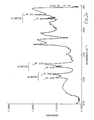
- Figures 2A-C show FTIR spectra for various minerals and mineral combinations;
- Figures 3A-D show mud product calibration curves;
- Figures 4A-D show mineral calibration curves;
- Figure 5 shows the correlation between results accuracy and gypsum concentration;
- Figures 6A-D show further mud product calibration curves; and
- Figures7A-C show further mineral calibration curves.
- An evaluation of mud product and mineral components in drilled cuttings/solids and various mud streams flowing through the mud circulation equipment may be used to compile a number of mass balances each of which is designed to assess various aspects of a mud engineering service during drilling. Five such mass balances have been identified in Table 1; each mass balance requires an evaluation of one or more mud products and/or mineral components in the indicated input and output streams. As an example, detailed procedures and considerations for a compilation of mass balance A are described below.
- The input mass of return mud dumped onto a shale shaker per unit time is equal to the output mass of drilled cuttings plus the mass of shaker underflow mud generated per unit time. The unit of time across which a representative mass balance may be compiled will depend on working conditions during drilling.
- During drilling, the mass of drilled material generated per unit time, A, will depend on the rate of penetration (ROP), the hole diameter (hd) and the average formation density (
ρ (f)):

ROP = 0.00254 m/s (30 ft/hr);
hd = 0.31115 m (12¼ inches);
ρ (f) = 2600 kg/m³ (2.6 kg/l);
Q(rm) - 0.020 m³/s (20 l/s); and
ρ(rm) -1200 kg/m³ (1.2 kg/l)
a substitution of these values gives:
A = 0.502 kg/s; and
B = 0.0209.
For such a typical example, a representative shale shaker mass balance may be obtained by evaluating input and output material over a five minute period. Five minutes of drilling deepens the wellbore by 0.762m and generates 150.48 kg of drilled material which is carried to the surface in 0.6 m³ (7200 kg) of return mud. Assuming that the shale shaker removes (i) 60 wt.% of the drilled material and (ii) one litre of mud per one litre of formation drilled, then the 7200 kg batch of input return mud will generate 159.74 kg of output "wet" drilled cuttings (containing 90.29 kg drilled material and 69.46 kg return mud) and 7040.26 kg of output shaker underflow mud. - In order to achieve the mud engineering objective(s) for the shale shaker mass balance (refer to Table 1), it is necessary to evaluate the composition of input and output streams. The accuracy of such an evaluation depends on:
- Representative primary sampling of input and output streams.
- Representative secondary sampling of primary samples in order to obtain suitable sub-samples for analysis.
- Accurate quantification of mud product and/or mineral component(s) in sub-samples. - Representative primary samples of the input return mud stream and output shaker underflow stream may be conveniently obtained by taking a one litre sample from well mixed "averaging" tanks (as proposed in the patent specification of British Patent Application No: 8926778.5). For example, a one litre primary sample of return mud taken from a well mixed averaging tank containing a 0.6 m³ mud volume in steady state represents 0.6 m³ of input return mud.
- Representative primary samples of drilled cuttings generated from the 0.6 m³ input batch of return mud may be conveniently sampled by a device such as a mechanical sample receiver which collects "oversize" material falling off 5% of the shaker screen width; the sample receiver moves across the full width of the shaker at an optimum frequency during the sampling period in order to ensure that the primary sample collected represents the entire output stream. Such a mechanical sample receiver will take a 5% cut of the entire output stream - ie a 0.0046 m³ (7.96 kg) primary sample is taken from the total of 0.0926 m³ (159.46 kg) of "wet" drilled cuttings material generated from the 0.6 m³ (7200 kg) input batch of return mud. The pre-tared sample receiver is reweighed after collection of the primary sample; the primary sample weight, M(ps) is used to calculate the weight of the entire output stream, C using the following relationship:

- The primary sample is thoroughly homogenised using a high speed blender prior to taking a secondary sample for subsequent analysis. In practice, it may be necessary to add a known weight of deionised water to the primary sample in order to achieve thorough homogenisation. The secondary sample is analysed as follows:
- A known sample volume is weighed in order to determine sample density; a known sample weight is then dried to constant weight in order to determine the weight fraction of solids, W(s); due corrections for the known weight of deionised water added in order to homogenise the primary sample and the weight of residual salts in the dried solids residue are taken into account. Procedures for the determination of mud product and/or mineral component(s) in the dried solids samples are given hereinbefore.
- A typical shale shaker mass balance is shown in Table 2. Such a mass balance may be compiled on a regular basis so as to assess drilled solids removal efficiency and to account for losses of mud products during a mud engineering service. The efficiency of solids removal by the shale shaker(s) and other solids control devices depends on the particle size distribution of drilled solids contained in the return mud; regular mass balancing may be used to optimise drilled solids removal efficiency according to drilled lithology. Field data has indicated that approximately one litre of return mud is removed by a shale shaker per one litre of formation drilled; the mass balance given in Table 2 assumes such a mud removal, and further indicates that, when using a typical weighted mud formulation, 20 kg of barite is removed per m³ of return mud loaded onto the shale shaker (at this rate, over a 24 hour period nearly six metric tons of barite would be removed).
- Experimental data obtained from an evaluation of drilled cuttings/solids generated from two different formations using two different mud formulations are given hereinafter.
- The dried mud solids and polymers are prepared for quantification using infrared spectroscopy. Firstly, there is taken an accurate weight of dried mud solids and polymers. This may be used as it is or it may be mixed with a halide salt (such as potassium bromide or sodium chloride), the chosen concentration of mud solids being about 5 weight percent (the halide salt decreases the difference of refractive indexes between the air and the mixture, and therefore decreases the loss of infrared radiation by reflection on the solids, but the dilution may result in trace components becoming undetectable). The whole is ground in a ball mill or pestle and mortar, preferably made of agate to minimise contamination from the material of the mill during grinding, to form a powder the particle size of which is below 2 microns, ie the smallest wavelength in the mid-infrared range. Such a particle size can be achieved within a few minutes using a small grinding mill - eg a Wig-L-Bug microniser manufactured by Crescent Dental Manufacturing Company of the USA.
- The powdered sample is placed in a diffuse reflectance cell, and the spectrum collected by an infrared spectrometer, preferably a Fourier transform infrared spectrometer. The equivalent transmission spectrum can be obtained by performing the Kubelka-Munk transform on the raw reflective spectrum data. This transform is described for example in the book Reference Spectroscopy by G Kortoem, a Springer-Verlag publication, 1969. Such a transform is convenient only but not essential for the quantification; the diffuse reflectance spectrum corresponds to infrared radiation emitted by the solids molecules following their absorption of the radiation emitted by the infrared source of the spectrometer.
- An alternative and better-known technique to collect the infrared spectrum of the mud solids is by direct transmission. The mixture of mud solids and halide salt is pressed into a solid disc (pellet) using a press capable of exerting loads of up to 10 tonnes. However, for the quantification of mud solids the diffuse reflectance technique is preferred for the reasons given hereinbefore.
- The diffuse reflectance spectrum of the recovered mud solids can be interpreted quantitatively using a number of techniques, including the Beer-Lambert law. In accordance with this law, there is a linear relationship between the diffuse reflectance - or the absorbance - of a product and its concentration at a single, fixed frequency, and the spectrum of a mixture can be analysed in terms of characteristic value of frequency for each of its individual components. However, a multivariate statistical technique, which uses the absorbance at a number of wavelengths, is preferred since a mixture of several components often results in marked deviations in the Beer-Lambert law. The spectrum of a mixture can be considered to be a linear combination of those of the pure components, and calibrations must be developed from the spectra of such mixtures. Multivariate statistical techniques can be used to generate a calibration model of the dried mud solids; the model essentially consists of a regression (or partial regression) of the spectral and concentration data sets of standards of accurately known compositions. Examples of such multivariate techniques are multiple linear regression, principal components analysis, and partial least squares path modelling. This last technique is preferred, and is described in the book Multivariate Calibration by H Martens and T Naes, a Wiley publication, 1989. An example of a computer programme to perform the partial least squares regression is the well-known UNSCRAMBLER software, developed at the Norwegian Food Research Institute and described in the journal Chemometrics and Intelligent Laboratory Systems,
Volume 2, pages 239-243, 1987. - A typical weighted mud formulation containing bentonite, low viscosity carboxymethyl cellulose (CMC-LV), xanthan gum (XC) and barite was used to drill through formations of dolomitic limestone and gypsum. Average concentrations of each of the four mud products in the mud formulation are given below:
Bentonite 36 g/l CMC-LV 10 g/l XC 1 g/l Barite 180 g/l - In order to quantify each of the mud products and formation minerals in samples of the drilled cuttings/solids generated during drilling, a quantitative calibration model was constructed using duplicate spectra for each of 21 calibration standards. Each standard was prepared by thoroughly mixing known weights of each pure component such that the weight fraction of each component varied within the ranges listed below:

- Whilst the composition of the calibration standards is dominated by a weight fraction of mineral components between 0.7835 and 0.9342, the weight fractions of mud product components constitute between 0.0658 and 0.2165 of the total composition. The xanthan gum (XC) component, originally present within a concentration range of 0.8 - 4.2 g/l in the original mud formulation, constitutes a low weight fraction range of 0.0005 - 0.0032 in the calibration standards.
- A total weight of two grams of each calibration standard was prepared; duplicate sub-samples of 0.45 grams were used to obtain a total of 42 FTIR spectra for the 21 calibration standards. Correlation coefficients for the calibration model generted from each of the 42 spectra are listed below:
Component Calibration coefficient Comment Bentonite 0.972 acceptable CMC-LV 0.977 acceptable XC 0.993 acceptable Barite 0.990 acceptable Dolomite 0.999 excellent (maximum) Calcite 0.991 acceptable Gypsum 0.999 excellent (maximum) Quartz 0.999 excellent (maximum) - Whilst the calibration correlation coefficients for the quantification of the major minerals (dolomite, gypsum and quartz) are at a maximum, the corresponding coefficients for the minor mineral component (calcite) and the mud product components (bentonite, CMC-LV, XC and barite), are well above acceptable limits for their accurate quantification. Figures 2a, 2b and 2c show FTIR spectra for three calibration standards dominated by dolomite (Figure 2a), gypsum and barite (Figure 2b) and gypsum and quartz (Figure 2c). Absorbance peaks due to fundamental vibrations of dolomite (
v 
v 
- Figures 3a, 3b, 3c and 3d show the calibration curves used to quantify the mud product components (bentonite, CMC-LV, XC and barite, respectively). Corresponding curves used for the quantification of dolomite, calcite, gypsum and quartz are shown in Figures 4a, 4b, 4c and 4d.
- Results for a series of six test drilled cuttings/solids samples are given in Table 3. The samples (1 to 6) represent drilled cuttings samples generated by drilling across a lithological boundary between an upper dolomite limestone (containing dolomite with some quartz) and a lower gypsum deposit (containing gypsum and quartz).
- The four mud product components (bentonite, CMC-LV, XC and barite) are quantified in the test samples within average relative accuracies of ±10%, ±13%, ±30% and ±4% respectively. The relatively low accuracy of predicting XC concentrations in the test samples is attributed to a low absolute XC concentration range which may be nearing the lower limits for spectral deconvolution. However, the accuracy of predicting bentonite, CMC-LV and barite concentrations in the test samples is sufficient to justify a routine analysis of cuttings/solids removed by the solids control equipment in order that the three mud products are regularly accurately accounted for during the mud engineering service.
- The four mineral components (dolomite, calcite, gypsum and quartz) are quantified in the test samples within average relative accuracies of ±3%, ±11%, ±12% and ±7% respectively. The relationship between relative accuracy for prediction of gypsum concentration and absolute gypsum concentration is shown in Figure 5; clearly, the relative inaccuracy of predicting a gypsum concentration below approximately 3% must be taken into account when using such analyses to determine the efficiency of removing drilled solids generated at the interface between the upper dolomitic limestone and the lower gypsum deposit.
- A typical weighted mud formulation containing bentonite, polyanionic cellulose (PAC), ferrochrome lignosulphonate (FCL), lignite, an asphaltene product, barite and diesel oil was used to drill through an upper formation "A" (containing calcite, quartz, and kaolinite) and a lower formation "B" (containing dolomite and anhydrite). Average concentrations of each of the seven mud products in the mud formulation are given below:
Bentonite 50 g/l PAC 5 g/l FCL 15 g/l Lignite 15 g/l Asphaltene 15 g/l Barite 180 g/ l Diesel oil 50 ml/l - In order to evaluate both the mud product and mineral components in return mud samples, a quantitative calibration model was constructed using duplicate spectra for each of 22 calibration standards. Each calibration mixture contains each mud product and mineral component varying in the weight fraction ranges listed below:

- Duplicate sub-samples of each calibration standard were used to obtain a total of 44 FTIR spectra; calibration coefficients for the 12 component calibration model are listed below:
Component Calibration coefficient Comment Bentonite 0.957 acceptable PAC 0.991 acceptable FCL 0.994 acceptable Lignite 0.998 acceptable Asphaltene 0.993 acceptable Barite 0.992 acceptable Diesel oil 0.993 acceptable Calcite 0.935 acceptable Quartz 0.998 acceptable Kaolinite 0.998 acceptable Dolomite 0.999 acceptable (maximum) Anthydrite 0.999 acceptable (maximum) - Calibration coefficients for all twelve components are well above acceptable limits for their quantification. For example, Figures 6a, 6b, 6c and 6d show the calibration curves used to quantify PAC, FCL, Asphaltene and Diesel oil; corresponding curves for calcite, quartz and kaolinite are shown in Figures 7a, 7b and 7c.
- The quantification of diesel oil in a return mud and/or drilled cuttings/solid sample deserves special note. Sample preparation involves drying to constant weight so as to determine the weight fraction of solids, W(s). A drying temperature of 160oC may be used to keep drying time to a minimum. At such a drying temperature, a large fraction of the diesel oil is volatile. However, the volatile fraction of a particular diesel oil will be a constant for a set drying temperature. Therefore, the concentration variance for diesel oil in calibration standards will be maintained through such a drying stage. FTIR spectra will show absorbance peaks due to the non- volatile fraction; such spectral information is well correlated with concentration variance for a set of calibration standards as shown in Figure 6d. The determination of diesel oil in an unknown sample involves a measurement using the calibration curve and a correction for the volatile fraction.
- Results for a series of three test return mud samples are given in Table 4.
Test mud samples test mud sample 3 also contains drilled material from formation "B". Over 80% lof the data lies within a relative accuracy of ±10%. Drilled minerals are satisfactorily quantified together with a simultaneous analysis of the seven mud components.Table 1 Mass balances designed to assess various aspects of a mud engineering service Mass Balance Objective(s) Evaluated Stream(s) Inputs(s) Output(s) Sample Name Sampling Point Sample Name Sampling Point A Assess drilled solids removal efficiency and mud products removed by shale shaker Return mud 38 Drilled cuttings 40 Shaker underflow 44 B Assess drilled solids removal efficiency and mud products removed by solids control equipement Shaker underflow 44 Drilled solids 42 Solids control underflow 46 C (A & B) Assess drilled solids removal efficiency and mud products removed by shale shaker and solids control equipment Return mud 38 Drilled cuttings 40 Drilled solids 42 Solids control underflow 46 D Assess hole stability for a drilled interval based on an indication of hole gauge. Assess mud product-formation component interactions Suction mud 16 Return mud 38 E Assess mixing properties of active tank Solids control underflow 46 Suction mud 16 Added "make-up" mud 10 Added mud products 10 

Claims (16)
- the sample is homogenised;
- a known weight of the homogenised sample is dried to constant weight, and the weight fraction of solids, W(s), in the sample is determined;
- the dried solids are crushed and homogenised to form a powder suitable for quantitative infrared analysis, and the powder is analysed in a IR spectrometer in order to obtain an infrared spectrum; and
- knowing the solids weight fraction, a value representative of the quantity of at least one of the mud product components and/or at least one of the mineral components in the sample is determined from the spectrum.
Applications Claiming Priority (6)
| Application Number | Priority Date | Filing Date | Title |
|---|---|---|---|
| GB8924346 | 1989-10-28 | ||
| GB8924346A GB2237303A (en) | 1989-10-28 | 1989-10-28 | Method of quantitative analysis of drilling fluid products |
| GB9011527A GB2237304A (en) | 1989-10-28 | 1990-05-23 | Method of quantitative analysis of drilling fluid products |
| GB9011527 | 1990-05-23 | ||
| GB9014870A GB2237305B (en) | 1989-10-28 | 1990-07-05 | Analysis of drilling solids samples |
| GB9014870 | 1990-07-05 |
Publications (2)
| Publication Number | Publication Date |
|---|---|
| EP0426231A2 true EP0426231A2 (en) | 1991-05-08 |
| EP0426231A3 EP0426231A3 (en) | 1991-09-04 |
Family
ID=27264766
Family Applications (1)
| Application Number | Title | Priority Date | Filing Date |
|---|---|---|---|
| EP19900202795 Withdrawn EP0426231A3 (en) | 1989-10-28 | 1990-10-19 | Analysis of drilling solids samples |
Country Status (5)
| Country | Link |
|---|---|
| US (1) | US5161409A (en) |
| EP (1) | EP0426231A3 (en) |
| CA (1) | CA2028053A1 (en) |
| GB (1) | GB2237305B (en) |
| NO (1) | NO904659L (en) |
Cited By (6)
| Publication number | Priority date | Publication date | Assignee | Title |
|---|---|---|---|---|
| WO1993017326A1 (en) * | 1992-02-29 | 1993-09-02 | Sedco Forex Technology Inc | Analysis of drilling fluids |
| WO2004009951A1 (en) * | 2002-07-23 | 2004-01-29 | Halliburton Energy Services, Inc. | System and method for developing and recycling drilling fluids |
| CN102943660A (en) * | 2010-04-12 | 2013-02-27 | 国际壳牌研究有限公司 | Method for estimating efficiency of bore-cleaning operation of drilling |
| EP2454584A4 (en) * | 2009-07-17 | 2014-10-29 | Atlas Copco Rock Drills Ab | METHOD FOR DETERMINING OIL CONTENT OF DRILLING DRAIN |
| EP2304174A4 (en) * | 2008-05-22 | 2015-09-23 | Schlumberger Technology Bv | UNDERGROUND MEASUREMENT OF TRAINING CHARACTERISTICS DURING DRILLING |
| EP2348306A4 (en) * | 2008-11-04 | 2016-06-29 | Ingenieros Mat Consultores Asoc S A | Method and system for measuring the concentration of different compounds present in particulate material |
Families Citing this family (53)
| Publication number | Priority date | Publication date | Assignee | Title |
|---|---|---|---|---|
| GB2237303A (en) * | 1989-10-28 | 1991-05-01 | Services Tech Sedco Forex | Method of quantitative analysis of drilling fluid products |
| GB9107041D0 (en) * | 1991-04-04 | 1991-05-22 | Schlumberger Services Petrol | Analysis of drilling fluids |
| GB2284887B (en) * | 1993-12-17 | 1997-12-10 | Pumptech Nv | Method of analysing drilling fluids |
| SE503101C2 (en) * | 1994-05-18 | 1996-03-25 | Eka Nobel Ab | Ways of determining the wet strength of paper and process control means using the method |
| DE19921549A1 (en) * | 1999-05-11 | 2000-11-16 | Merck Patent Gmbh | Grinding aids for X-ray fluorescence analysis |
| US6194216B1 (en) | 2000-02-16 | 2001-02-27 | Baker Hughes Incorporated | Method for determination of amine-based additives in drilling fluid filtrates |
| US20020112888A1 (en) | 2000-12-18 | 2002-08-22 | Christian Leuchtenberg | Drilling system and method |
| US7095012B2 (en) * | 2000-12-19 | 2006-08-22 | Schlumberger Technology Corporation | Methods and apparatus for determining chemical composition of reservoir fluids |
| US6453738B1 (en) * | 2001-04-10 | 2002-09-24 | Cesmat Service Company, Inc. | Method and apparatus for analyzing casing wear and retrieval of metallic fragments |
| US20030037922A1 (en) * | 2001-08-27 | 2003-02-27 | Apv North America, Inc. | System and method for processing oil-based mud cuttings |
| US7050166B2 (en) | 2001-11-02 | 2006-05-23 | Baker Hughes Incorporated | Calcium carbonate imaging technique |
| US6662884B2 (en) * | 2001-11-29 | 2003-12-16 | Halliburton Energy Services, Inc. | Method for determining sweep efficiency for removing cuttings from a borehole |
| US7150183B2 (en) * | 2003-06-19 | 2006-12-19 | Schlumberger Technology Corporation | Compositional characterization and quantification of solid deposits from hydrocarbon fluids |
| US20060011547A1 (en) * | 2004-07-13 | 2006-01-19 | Bell Stephen A | Methods of separating components in treatment fluids |
| WO2006138632A2 (en) * | 2005-06-16 | 2006-12-28 | Thermo Gamma-Metrics Llc | In-stream spectroscopic elemental analysis of particles being conducted within a gaseous stream |
| FI120164B2 (en) * | 2008-02-15 | 2012-07-13 | Mine On Line Service Oy | Procedure and equipment to make ore exploration more efficient |
| CA2638405A1 (en) * | 2008-06-30 | 2009-12-30 | Konstandinos S. Zamfes | Method and apparatus for on-site drilling cuttings analysis |
| US9091151B2 (en) | 2009-11-19 | 2015-07-28 | Halliburton Energy Services, Inc. | Downhole optical radiometry tool |
| AU2009356978B2 (en) * | 2009-12-23 | 2013-08-01 | Halliburton Energy Services, Inc. | Interferometry-based downhole analysis tool |
| BR112012027653A2 (en) | 2010-06-01 | 2016-08-16 | Halliburton Energy Services Inc | method and system for measuring formation properties |
| AU2010355321B2 (en) | 2010-06-16 | 2014-02-27 | Halliburtion Energy Services, Inc. | Downhole sources having enhanced IR emission |
| US8950492B2 (en) * | 2011-07-20 | 2015-02-10 | Halliburton Energy Services, Inc. | Invert emulsion fluid containing a hygroscopic liquid, a polymeric suspending agent, and low-density solids |
| US9329122B2 (en) * | 2011-08-15 | 2016-05-03 | Schlumberger Technology Corporation | Diffuse reflectance infrared fourier transform spectroscopy for characterization of earth materials |
| US8906690B2 (en) | 2012-04-13 | 2014-12-09 | Schlumberger Technology Corporation | Methods for simultaneous estimation of quantitative minerology, kerogen content and maturity in gas shale and oil-bearing shale |
| US8967249B2 (en) * | 2012-04-13 | 2015-03-03 | Schlumberger Technology Corporation | Reservoir and completion quality assessment in unconventional (shale gas) wells without logs or core |
| WO2014022757A1 (en) * | 2012-08-02 | 2014-02-06 | Schlumberger Canada Limited | Method and apparatus for simultaneous estimation of quantitative mineralogy, kerogen content and maturity in gas shales and oil-bearing shales using vibrational spectroscopy |
| EP2703597A1 (en) * | 2012-09-03 | 2014-03-05 | Geoservices Equipements | Method of calibration for the use in a process of determining the content of a plurality of compounds contained in a drilling fluid |
| CA3226948A1 (en) | 2012-11-30 | 2014-05-30 | Suncor Energy Inc. | Measurement and control of bitumen-containing process streams |
| US10174569B2 (en) | 2013-06-20 | 2019-01-08 | Aspect International (2015) Private Limited | NMR/MRI-based integrated system for analyzing and treating of a drilling mud for drilling mud recycling process and methods thereof |
| US20160108687A1 (en) * | 2013-10-10 | 2016-04-21 | Aspect International (2015) Private Limited | Means and Methods for Multirnodality Analysis and Processing of Drilling Mud |
| US9494503B2 (en) | 2013-11-06 | 2016-11-15 | Aspect Imaging Ltd. | Inline rheology/viscosity, density, and flow rate measurement |
| CN105849536B (en) | 2013-11-08 | 2021-07-30 | 普拉德研究及开发股份有限公司 | Spectral Analysis Using Spectral Deconvolution |
| EP3066426B1 (en) | 2013-11-08 | 2022-04-13 | Services Pétroliers Schlumberger | Flow regime recognition for flow model adaptation |
| US10704346B2 (en) * | 2013-11-26 | 2020-07-07 | M-I L.L.C. | Apparatus, system and method for separating components of a slurry |
| US8812236B1 (en) * | 2014-04-11 | 2014-08-19 | Particle Size Engineering, LLC | Method for using particle size analysis in near time or real time to create a proper particle size distribution within a drilling fluid management system for improved well drilling efficiency |
| US10670574B2 (en) | 2015-01-19 | 2020-06-02 | Aspect International (2015) Private Limited | NMR-based systems for crude oil enhancement and methods thereof |
| CN106053299B (en) | 2015-04-12 | 2020-10-30 | 艾斯拜克特Ai有限公司 | NMR imaging of fluids in non-circular cross-section conduits |
| US10591388B2 (en) | 2015-04-27 | 2020-03-17 | Virtual Fluid Monitoring Services LLC | Fluid analysis and monitoring using optical spectroscopy |
| BR112017023320A2 (en) | 2015-04-27 | 2018-08-14 | Virtual Fluid Monitoring Services LLC | fluid analysis and monitoring systems, apparatus and methods |
| CN106324010A (en) | 2015-07-02 | 2017-01-11 | 艾斯拜克特Ai有限公司 | Analysis of fluids flowing in a conduit using MR equipment |
| CN105092590B (en) * | 2015-08-17 | 2018-01-26 | 大连理工大学 | An experimental device and method for hole-making process exit observation |
| EP3156587A1 (en) * | 2015-10-16 | 2017-04-19 | Services Pétroliers Schlumberger | Automated device for the analysis of drilling cuttings |
| AT518021B1 (en) * | 2015-12-14 | 2018-04-15 | Think And Vision Gmbh | Apparatus and method for analyzing drilling mud |
| US10655996B2 (en) | 2016-04-12 | 2020-05-19 | Aspect Imaging Ltd. | System and method for measuring velocity profiles |
| US10132958B2 (en) * | 2016-07-14 | 2018-11-20 | Schlumberger Technology Corporation | Determining an optical density linear dynamic range for an optical spectrometer |
| US11442019B2 (en) | 2018-06-19 | 2022-09-13 | Virtual Fluid Monitoring Services, Llc | Fluid analysis and monitoring using optical spectroscopy |
| US10684219B2 (en) | 2018-10-30 | 2020-06-16 | Chevron U.S.A. Inc. | Method for determining hydrocarbon concentration in drilled solids using near infrared spectroscopy |
| GB2581154B (en) * | 2019-02-05 | 2022-09-28 | Colvistec Ag | Amorphous pharmaceutical compositions |
| WO2021035273A1 (en) * | 2019-08-28 | 2021-03-04 | Crc Care Pty Ltd | A method of determining petroleum hydrocarbon fractions in a sample |
| CN113027363B (en) * | 2021-05-08 | 2022-04-08 | 中国石油大学(北京) | Application method of fractured formation drilling fluid |
| US12607618B2 (en) | 2023-04-24 | 2026-04-21 | Saudi Arabian Oil Company | System for automated legacy drill cutting samples digitization |
| CN118243638B (en) * | 2024-05-27 | 2024-08-27 | 西安石油大学 | Method and device for detecting solid phase content of drilling flow-back fluid in real time |
| CN121409891B (en) * | 2025-12-26 | 2026-04-28 | 大庆油田有限责任公司 | Methods, apparatus and equipment for detecting the original oil content in core samples obtained from oil-based drilling fluids |
Family Cites Families (11)
| Publication number | Priority date | Publication date | Assignee | Title |
|---|---|---|---|---|
| US4149804A (en) * | 1977-02-02 | 1979-04-17 | Occidental Oil Shale, Inc. | Method and apparatus for measuring chemical content of core samples |
| US4321465A (en) * | 1979-05-21 | 1982-03-23 | Occidental Research Corporation | Infrared assay of kerogen in oil shale |
| US4608859A (en) * | 1983-12-28 | 1986-09-02 | Microlytics, Inc. | Process and apparatus for analyzing cutting from oil and gas wells |
| FR2564200B1 (en) * | 1984-05-11 | 1986-10-03 | Inst Francais Du Petrole | PROCESS FOR ACQUIRING IMAGES OF GEOLOGICAL SAMPLES FOR OPTICAL ANALYSIS AND DEVICE FOR IMPLEMENTING SAME |
| US4800279A (en) * | 1985-09-13 | 1989-01-24 | Indiana University Foundation | Methods and devices for near-infrared evaluation of physical properties of samples |
| GB2202047A (en) * | 1987-03-09 | 1988-09-14 | Forex Neptune Sa | Monitoring drilling mud |
| US4839516A (en) * | 1987-11-06 | 1989-06-13 | Western Atlas International, Inc. | Method for quantitative analysis of core samples |
| GB2212611B (en) * | 1987-11-14 | 1991-08-14 | Forex Neptune Sa | A method of monitoring the drilling operations by analysing the circulating drilling mud |
| GB2217838A (en) * | 1988-04-15 | 1989-11-01 | Shell Int Research | Near infrared determination of petrophysical and petrochemical properties |
| US4996421A (en) * | 1988-10-31 | 1991-02-26 | Amoco Corporation | Method an system of geophysical exploration |
| GB2226412B (en) * | 1988-12-21 | 1993-04-28 | Forex Neptune Sa | Monitoring drilling mud compositions using flowing liquid junction electrodes |
-
1990
- 1990-07-05 GB GB9014870A patent/GB2237305B/en not_active Expired - Fee Related
- 1990-10-19 EP EP19900202795 patent/EP0426231A3/en not_active Withdrawn
- 1990-10-19 CA CA002028053A patent/CA2028053A1/en not_active Abandoned
- 1990-10-22 US US07/601,489 patent/US5161409A/en not_active Expired - Lifetime
- 1990-10-26 NO NO90904659A patent/NO904659L/en unknown
Cited By (10)
| Publication number | Priority date | Publication date | Assignee | Title |
|---|---|---|---|---|
| WO1993017326A1 (en) * | 1992-02-29 | 1993-09-02 | Sedco Forex Technology Inc | Analysis of drilling fluids |
| WO2004009951A1 (en) * | 2002-07-23 | 2004-01-29 | Halliburton Energy Services, Inc. | System and method for developing and recycling drilling fluids |
| US6932169B2 (en) | 2002-07-23 | 2005-08-23 | Halliburton Energy Services, Inc. | System and method for developing and recycling drilling fluids |
| EP2304174A4 (en) * | 2008-05-22 | 2015-09-23 | Schlumberger Technology Bv | UNDERGROUND MEASUREMENT OF TRAINING CHARACTERISTICS DURING DRILLING |
| EP2348306A4 (en) * | 2008-11-04 | 2016-06-29 | Ingenieros Mat Consultores Asoc S A | Method and system for measuring the concentration of different compounds present in particulate material |
| EP2454584A4 (en) * | 2009-07-17 | 2014-10-29 | Atlas Copco Rock Drills Ab | METHOD FOR DETERMINING OIL CONTENT OF DRILLING DRAIN |
| US9201029B2 (en) | 2009-07-17 | 2015-12-01 | Atlas Copco Rock Drills Ab | Method for determining the ore content of drill cuttings |
| CN102943660A (en) * | 2010-04-12 | 2013-02-27 | 国际壳牌研究有限公司 | Method for estimating efficiency of bore-cleaning operation of drilling |
| CN102943660B (en) * | 2010-04-12 | 2015-12-02 | 国际壳牌研究有限公司 | The method of the clear hole validity of assessment drill-well operation |
| US10415365B2 (en) | 2010-04-12 | 2019-09-17 | Shell Oil Company | Methods and systems for drilling |
Also Published As
| Publication number | Publication date |
|---|---|
| EP0426231A3 (en) | 1991-09-04 |
| GB2237305A (en) | 1991-05-01 |
| NO904659D0 (en) | 1990-10-26 |
| NO904659L (en) | 1991-04-29 |
| US5161409A (en) | 1992-11-10 |
| GB9014870D0 (en) | 1990-08-22 |
| CA2028053A1 (en) | 1991-04-29 |
| GB2237305B (en) | 1993-03-31 |
Similar Documents
| Publication | Publication Date | Title |
|---|---|---|
| EP0426231A2 (en) | Analysis of drilling solids samples | |
| EP0507405B1 (en) | Analysis of drilling fluids | |
| US5360738A (en) | Method of quantitative analysis of drilling fluid products | |
| US5557103A (en) | Method of analyzing drilling fluids | |
| Percival | Measurement of physical properties of sediments | |
| Saasen et al. | Automatic measurement of drilling fluid and drill-cuttings properties | |
| EP0398886B1 (en) | Method for quantitative analysis of core samples | |
| DE3881913T2 (en) | Method for controlling a drilling fluid. | |
| US20160108687A1 (en) | Means and Methods for Multirnodality Analysis and Processing of Drilling Mud | |
| US20150268374A1 (en) | Means and Methods for Multimodality Analysis and Processing of Drilling Mud | |
| US8906690B2 (en) | Methods for simultaneous estimation of quantitative minerology, kerogen content and maturity in gas shale and oil-bearing shale | |
| Herron et al. | Kerogen content and maturity, mineralogy and clay typing from DRIFTS analysis of cuttings or core | |
| US20110036785A1 (en) | Waste solid cleaning apparatus | |
| EP0426232B1 (en) | Method of quantitative analysis of drilling fluid products | |
| Atheaux et al. | Xrf-ftir data fusion and machine learning models for mineralogical analysis of solid mineral mixtures and solid dispersions in drilling fluids | |
| Mohnot | Characterization and control of fine particles involved in drilling | |
| Davison et al. | Rig-site monitoring of the drilling fluid solids content and solids-control equipment discharge | |
| Omland et al. | Improved drilling-process control through continuous particle and cuttings monitoring | |
| Underdown et al. | Minimize Formation Damage by Rapid, Inexpensive Method of Completion-and Stimulation-Fluid Selection | |
| Froment et al. | A drilling contractor tests solids control equipment | |
| Herron et al. | Clay typing, mineralogy, kerogen content and kerogen characterization from DRIFTS analysis of cuttings or core | |
| US20230152294A1 (en) | Method for analysis and detection of solids in emulsions, oil and derivatives thereof | |
| Hughes et al. | Chemical monitoring of mud products on drilled cuttings | |
| CN120971355A (en) | Methods for determining the primary barium or strontium isotopes and contents of barite mudstone fragments | |
| Geddes | Quantification of swelling clays in mineral mixtures and rocks using infrared spectroscopy |
Legal Events
| Date | Code | Title | Description |
|---|---|---|---|
| PUAI | Public reference made under article 153(3) epc to a published international application that has entered the european phase |
Free format text: ORIGINAL CODE: 0009012 |
|
| AK | Designated contracting states |
Kind code of ref document: A2 Designated state(s): DE DK FR IT NL |
|
| PUAL | Search report despatched |
Free format text: ORIGINAL CODE: 0009013 |
|
| AK | Designated contracting states |
Kind code of ref document: A3 Designated state(s): DE DK FR IT NL |
|
| 17P | Request for examination filed |
Effective date: 19910923 |
|
| 17Q | First examination report despatched |
Effective date: 19930429 |
|
| GRAH | Despatch of communication of intention to grant a patent |
Free format text: ORIGINAL CODE: EPIDOS IGRA |
|
| STAA | Information on the status of an ep patent application or granted ep patent |
Free format text: STATUS: THE APPLICATION HAS BEEN WITHDRAWN |
|
| 18W | Application withdrawn |
Withdrawal date: 19960220 |