EP0426233B1 - Verfahren zur Herstellung eines Schaufelrades oder eines Rotors mit einem oder mehreren Schaufeln für eine Turbinenpumpe mittels Funkenbearbeitung und dessen Erzeugnisse - Google Patents
Verfahren zur Herstellung eines Schaufelrades oder eines Rotors mit einem oder mehreren Schaufeln für eine Turbinenpumpe mittels Funkenbearbeitung und dessen Erzeugnisse Download PDFInfo
- Publication number
- EP0426233B1 EP0426233B1 EP90202808A EP90202808A EP0426233B1 EP 0426233 B1 EP0426233 B1 EP 0426233B1 EP 90202808 A EP90202808 A EP 90202808A EP 90202808 A EP90202808 A EP 90202808A EP 0426233 B1 EP0426233 B1 EP 0426233B1
- Authority
- EP
- European Patent Office
- Prior art keywords
- rotor
- blades
- tool
- impeller
- slits
- Prior art date
- Legal status (The legal status is an assumption and is not a legal conclusion. Google has not performed a legal analysis and makes no representation as to the accuracy of the status listed.)
- Expired - Lifetime
Links
Images


Classifications
-
- B—PERFORMING OPERATIONS; TRANSPORTING
- B23—MACHINE TOOLS; METAL-WORKING NOT OTHERWISE PROVIDED FOR
- B23H—WORKING OF METAL BY THE ACTION OF A HIGH CONCENTRATION OF ELECTRIC CURRENT ON A WORKPIECE USING AN ELECTRODE WHICH TAKES THE PLACE OF A TOOL; SUCH WORKING COMBINED WITH OTHER FORMS OF WORKING OF METAL
- B23H9/00—Machining specially adapted for treating particular metal objects or for obtaining special effects or results on metal objects
- B23H9/10—Working turbine blades or nozzles
-
- F—MECHANICAL ENGINEERING; LIGHTING; HEATING; WEAPONS; BLASTING
- F04—POSITIVE - DISPLACEMENT MACHINES FOR LIQUIDS; PUMPS FOR LIQUIDS OR ELASTIC FLUIDS
- F04D—NON-POSITIVE-DISPLACEMENT PUMPS
- F04D19/00—Axial-flow pumps
- F04D19/02—Multi-stage pumps
- F04D19/04—Multi-stage pumps specially adapted to the production of a high vacuum, e.g. molecular pumps
- F04D19/042—Turbomolecular vacuum pumps
-
- F—MECHANICAL ENGINEERING; LIGHTING; HEATING; WEAPONS; BLASTING
- F04—POSITIVE - DISPLACEMENT MACHINES FOR LIQUIDS; PUMPS FOR LIQUIDS OR ELASTIC FLUIDS
- F04D—NON-POSITIVE-DISPLACEMENT PUMPS
- F04D29/00—Details, component parts, or accessories
- F04D29/02—Selection of particular materials
- F04D29/023—Selection of particular materials especially adapted for elastic fluid pumps
-
- F—MECHANICAL ENGINEERING; LIGHTING; HEATING; WEAPONS; BLASTING
- F04—POSITIVE - DISPLACEMENT MACHINES FOR LIQUIDS; PUMPS FOR LIQUIDS OR ELASTIC FLUIDS
- F04D—NON-POSITIVE-DISPLACEMENT PUMPS
- F04D29/00—Details, component parts, or accessories
- F04D29/26—Rotors specially for elastic fluids
- F04D29/32—Rotors specially for elastic fluids for axial flow pumps
- F04D29/321—Rotors specially for elastic fluids for axial flow pumps for axial flow compressors
- F04D29/324—Blades
-
- Y—GENERAL TAGGING OF NEW TECHNOLOGICAL DEVELOPMENTS; GENERAL TAGGING OF CROSS-SECTIONAL TECHNOLOGIES SPANNING OVER SEVERAL SECTIONS OF THE IPC; TECHNICAL SUBJECTS COVERED BY FORMER USPC CROSS-REFERENCE ART COLLECTIONS [XRACs] AND DIGESTS
- Y10—TECHNICAL SUBJECTS COVERED BY FORMER USPC
- Y10T—TECHNICAL SUBJECTS COVERED BY FORMER US CLASSIFICATION
- Y10T29/00—Metal working
- Y10T29/37—Impeller making apparatus
-
- Y—GENERAL TAGGING OF NEW TECHNOLOGICAL DEVELOPMENTS; GENERAL TAGGING OF CROSS-SECTIONAL TECHNOLOGIES SPANNING OVER SEVERAL SECTIONS OF THE IPC; TECHNICAL SUBJECTS COVERED BY FORMER USPC CROSS-REFERENCE ART COLLECTIONS [XRACs] AND DIGESTS
- Y10—TECHNICAL SUBJECTS COVERED BY FORMER USPC
- Y10T—TECHNICAL SUBJECTS COVERED BY FORMER US CLASSIFICATION
- Y10T29/00—Metal working
- Y10T29/49—Method of mechanical manufacture
- Y10T29/49316—Impeller making
- Y10T29/4932—Turbomachine making
- Y10T29/49325—Shaping integrally bladed rotor
Definitions
- the present invention relates to a process for manufacturing, by means of electrical discharge machining (EDM) techniques, an impeller or a rotor having one or more impellers, in a turbine pump, particularly a turbomolecular pump, as well as to the impeller or the rotor obtained through such process.
- EDM electrical discharge machining
- a rotor in a turbomolecular pump is made up by a series of impellers that are keyed to a rotating shaft.
- Each impeller comprises a disk equipped with an array of radial peripheral blades and is foreseen for rotating, in use, at a speed up to several tens of thousands rpm.
- each impeller is built by milling the blades thereof by means of an apparatus that allows for the simultaneous machining of several disks. Nevertheless such machining requires several steps and is such as to impose limitations to the article characteristics: for example the gap between the blades cannot be smaller than certain values being determined by the employed cutting methods. Moreover, the problems relating to keying the impellers to the shaft remain unsolved.
- An object of the present invention is that of overcoming or reducing the drawbacks of the known processes for manufacturing rotors of turbomolecular pumps, by providing a process that is both quick and adapted to produce an impeller or a rotor having high operating characteristics.
- a process for manufacturing an impeller or a rotor having one or more blades for a turbine pump comprising a preliminary step of preparing a workpiece, comprising at least a disk corresponding to the impeller to be realized, which is placed within an apparatus for electrical discharge machining in such a manner as to act as an electrode thereof, characterized in that said disk is passed through a tool acting as the other electrode with a combined motion of rotation and translation, said tool comprising at least one plate in which radial slits are formed along at least an arc of circumference, said slits opening into a hollow area defined within said plate, so that an impeller blade is produced for each of said slits in said tool thanks to said combined motion of rotation and translation of said disk through said tool.
- Another object of the invention resides in a process for obtaining a whole impeller by means of a single operation of electrical discharge machining, this process being characterized by the use of a tool provided with radial slits along a complete circular crown that is hollow at its center.
- An additional object of the invention resides in a process for directly obtaining a rotor having one or more impellers from one or more disks already fastened to the rotor shaft, the process being characterized in that said disks are passed through one or more tools provided with radial slits as already explained.
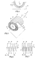
- FIG. 1 and 2 a process for realizing a rotor impeller for turbomolecular pumps through electrical discharge machining, is schematically illustrated, the tool being indicated at 1 and the workpiece at 2. Both these members are placed in an electrical discharge machine that has not been shown since it is known per se, the tool constituting one electrode and the workpiece the other one.
- the tool is made up by a plate 4 in which a series of equally spaced slits 5 radially extending along a circular crown, and opening towards the center into a through hole 7 in the plate.
- the workpiece 2 is made up by a metal disk having a size corresponding to that of the desired impeller and is either keyed to a shaft 3 or integrally formed with the shaft itself.
- the disk radius is equal to or smaller than the sum of the radius of the hole 7 and the length of the slit 5.
- the shaft 3 is mounted on a workhead that can be translated along the three cartesian axes and is further rotatable about the Z axis, under numerical control. As an alternative, the workpiece can be kept still and the tool 1 be moved, in any case obtaining a relative combined motion of rotation and translation between the workpiece and the tool.
- Figure 4 shows a tool formed by a plate 10 in which radial slits 5′ have been cut along a semicircumference, around a semicircular recess 12 formed in a side 13 of plate 1.
- the tool is "open” and is adapted for carrying out the process in a situation in which a plurality of disks 2 are already keyed to the shaft, or in an equivalent situation being nevertheless more interesting for practical purposes, wherein the shaft 3 and the disks 2 are integrally formed as a one-piece (monolithic) semifinished product, obtained e.g. by turning or milling a metal cylinder.
- the workpiece is constituted by a shaft 3 comprising a series of disks 2a, 2b, ..2n, fastened to a workhead of the electrical discharge machine.
- the tool comprises an array of plates 10a, 10b, 10n formed like the plate 10 of Figure 4.
- the disks 2a, ... 2n are inserted through the plates 10a, ... 10n as shown in Fig. 6.
- Fig. 5 shows only one of such plates for an easier illustration.
- each disk 2 passes through the corresponding plate 10 so that half of the impeller blades are formed on each disk, that is all the blades foreseen on a disk semicircumference.
- Figure 7 which illustrates the so formed blades 9.
- the workpiece is then rotated either by (180- ⁇ )° in the same direction of rotation as angle ⁇ , or in the opposite direction by (180+ ⁇ )°, is subjected to another rotation and translation passage through the tools, by again moving the workpiece along the Z axis, but in opposite direction, and thus obtaining an impeller complete with all the blades.
- Figures 8 and 9 are a side view and a plan view respectively, of a blade 9 obtained through the process of the present invention.
- the numeral reference 9 indicates the profile of the radially inner part of blade 9, tilted at an angle ⁇ 1, with respect to the horizontal
- reference 13 indicates the profile the blade assumes in its peripheral portion, which is tilted at an angle ⁇ 2 with respect to the horizontal.
- the twist of the blade is due to the variation of this profile along the radius.
- the above structural feature of the blade obtained thanks to the combination of the rotation and translation motions of the workpiece passing through the tool, imparts advantageous properties to the impeller, particularly of rotors for turbomolecular pumps, since it optimizes the compression ratio and the pumping speed.
Landscapes
- Engineering & Computer Science (AREA)
- Mechanical Engineering (AREA)
- General Engineering & Computer Science (AREA)
- Physics & Mathematics (AREA)
- Thermal Sciences (AREA)
- Electrical Discharge Machining, Electrochemical Machining, And Combined Machining (AREA)
- Structures Of Non-Positive Displacement Pumps (AREA)
- Non-Positive Displacement Air Blowers (AREA)
- Turbine Rotor Nozzle Sealing (AREA)
Claims (11)
- Verfahren zur Herstellung eines Schaufelrades oder eines Rotors mit einer oder mehreren Schaufeln für eine Turbinenpumpe, mit einem einleitenden Verfahrensschritt des Vorbereitens eines zumindest eine Scheibe (2) entsprechend dem zu fertigenden Schaufelrad aufweisenden Werkstückes, das in einer Einrichtung für elektroerosive Bearbeitung in der Weise in Stellung gebracht wird, daß es als eine ihrer Elektroden wirkt, dadurch gekennzeichnet, daß die genannte Scheibe (2) durch ein als die andere Elektrode wirkendes Werkzeug (1) mit einer aus Rotation und Translation kombinierten Bewegung hindurchbewegt wird, wobei das genannte Werkzeug zumindest eine Platte (4; 10) aufweist, in der radiale Schlitze (5; 5′) längs zumindest eines Umfangsbogens ausgebildet sind, und die genannten Schlitze (5; 5′) in einen hohlen Bereich (7; 12) hinein offen sind, der innerhalb der genannten Platte definiert ist, so daß für jeden der genannten Schlitze (5; 5′) in dem genannten Werkzeug eine Radschaufel (9) erzeugt wird dank der genannten, aus Rotation und Translation kombinierten Bewegung der genannten Scheibe (2) durch das genannte Werkzeug (1) hindurch.
- Verfahren nach Anspruch 1, dadurch gekennzeichnet, daß der genannte hohle Bereich (7; 12) ein kreisrunder Bereich ist und daß der Radius der genannten Scheibe (2) kleiner als oder gleich groß wie die Summe aus dem Radius des genannten kreisrunden Bereichs und der Länge der genannten Schlitze (5) ist.
- Verfahren nach den vorausgehenden Ansprüchen, dadurch gekennzeichnet, daß die genannte Werkzeug-Kathode (1) eine Platte aufweist, in der Schlitze (5) in gleichmäßigen Abständen längs einer kreisrunden Krone angeordnet sind, und daß der genannte hohle Bereich eine kreisrunde Öffnung (7) ist.
- Verfahren nach den Ansprüchen 1 und 2, dadurch gekennzeichnet, daß das genannte Werkzeug eine Platte (10) aufweist, in der die genannten Schlitze (5′) in gleichmäßigen Abständen längs eines Halbkreises angeordnet sind, und daß der genannte hohle Bereich eine halbkreisförmige Ausnehmung (12) ist, die an einer Seite (13) der Platte ausgebildet ist.
- Verfahren nach Anspruch 4, dadurch gekennzeichnet, daß das genannte Werkstück eine Welle (3), die eine Mehrzahl fest angebrachter Scheiben (2a,... 2n) trägt, und das genannte Werkzeug eine Mehrzahl von Plattten (10a,...10n) aufweisen, daß jede der genannten Scheiben (2a,...2n) im Betrieb zwischen zwei benachbarte, genannte Platten (10a,...10n) eingeführt wird, daß die genannten Scheiben (2a,...2n) gegen die genannten Platten hin mit einer aus Rotation und Translation kombinierten Bewegung bewegt werden, um eine erste Hälfte der genannten Radschaufeln (9) zu erhalten, und daß dann das genannte Werkstück in solcher Weise, daß der unbearbeitete Teil der genannten Scheiben (2a,...2n) dem Werkzeug ausgesetzt wird, gedreht und wiederum gegen die genannten Platten (10a,...10n) hin mit einer aus Rotation und Translation kombinierten Bewegung längs der gleichen Bahn bewegt wird, jedoch in Rückwärtsrichtung.
- Verfahren nach den Ansprüchen 4 und 5, dadurch gekennzeichnet, daß das genannte, durch Elektroerosion zu bearbeitende Werkstück ein einstückiges Halbzeug ist.
- Rotor für eine Turbinenpumpe, der durch das Verfahren nach einem der Ansprüche 1 bis 6 hergestellt ist, dadurch gekennzeichnet, daß die Schaufelräder mit der genannten Welle einstückig sind.
- Rotor für eine Turbinenpumpe nach Anspruch 7, dadurch gekennzeichnet, daß die genannten Schaufelräder eine Reihe verwundener Radschaufeln (9) aufweisen.
- Rotor für eine Turbinenpumpe nach Anspruch 8, dadurch gekennzeichnet, daß jede der genannten Radschaufeln (9) einen konstanten Querschnitt in einer horizontalen Ebene und eine Dicke (s) aufweist, die sich in Abhängigkeit vom Radius ändert.
- Rotor für eine Turbinenpumpe nach Anspruch 8, dadurch gekennzeichnet, daß jede der genannten Radschaufeln (9) eine konstante Dicke (s) und einen querschnitt in einer horizontalen Ebene besitzt, der sich in Abhängigkeit vom Radius ändert.
- Rotor für eine Turbinenpumpe nach Anspruch 8, dadurch gekennzeichnet, daß sowohl die Dicke (s) als auch der Querschnitt in einer horizontalen Ebene sich bei jeder der genannten Radschaufeln (9) in Abhängigkeit vom Radius ändern.
Priority Applications (1)
| Application Number | Priority Date | Filing Date | Title |
|---|---|---|---|
| AT90202808T ATE85923T1 (de) | 1989-11-03 | 1990-10-20 | Verfahren zur herstellung eines schaufelrades oder eines rotors mit einem oder mehreren schaufeln fuer eine turbinenpumpe mittels funkenbearbeitung und dessen erzeugnisse. |
Applications Claiming Priority (2)
| Application Number | Priority Date | Filing Date | Title |
|---|---|---|---|
| IT6793889 | 1989-11-03 | ||
| IT06793889A IT1238201B (it) | 1989-11-03 | 1989-11-03 | Metodo di fabbricazione mediante elettroerosione di una girante o di un rotore a una o piu' giranti di una turbopompa, particolarmente di una pompa turbomolecolare, e prodotti cosi' ottenuti. |
Publications (2)
| Publication Number | Publication Date |
|---|---|
| EP0426233A1 EP0426233A1 (de) | 1991-05-08 |
| EP0426233B1 true EP0426233B1 (de) | 1993-02-24 |
Family
ID=11306531
Family Applications (1)
| Application Number | Title | Priority Date | Filing Date |
|---|---|---|---|
| EP90202808A Expired - Lifetime EP0426233B1 (de) | 1989-11-03 | 1990-10-20 | Verfahren zur Herstellung eines Schaufelrades oder eines Rotors mit einem oder mehreren Schaufeln für eine Turbinenpumpe mittels Funkenbearbeitung und dessen Erzeugnisse |
Country Status (6)
| Country | Link |
|---|---|
| US (1) | US5188514A (de) |
| EP (1) | EP0426233B1 (de) |
| JP (1) | JPH0755409B2 (de) |
| AT (1) | ATE85923T1 (de) |
| DE (1) | DE69000968T2 (de) |
| IT (1) | IT1238201B (de) |
Families Citing this family (23)
| Publication number | Priority date | Publication date | Assignee | Title |
|---|---|---|---|---|
| US6206182B1 (en) * | 1999-01-29 | 2001-03-27 | Cwa, Inc. | Co-injected labyrinth and contact seal for an idler roller assembly for a belt conveyor background of the invention |
| US6412173B1 (en) * | 1999-07-26 | 2002-07-02 | Phoenix Analysis And Design Technologies, Inc. | Miniature turbomolecular pump |
| IT1319495B1 (it) * | 2000-11-30 | 2003-10-20 | Nuovo Pignone Spa | Procedimento per la realizzazione di un rotore per compressoricentrifughi. |
| SE518806C2 (sv) * | 2001-03-14 | 2002-11-26 | Volvo Aero Corp | Förfarande och anordning för framställning av en stator- eller rotorkomponent |
| EP1249612B1 (de) | 2001-03-15 | 2004-01-28 | VARIAN S.p.A. | Herstellungsverfahren einer Statorstufe für eine Turbinenpumpe |
| US7204926B2 (en) | 2001-11-26 | 2007-04-17 | General Electric Company | Tandem blisk electrochemical machining |
| KR20040009436A (ko) * | 2002-07-23 | 2004-01-31 | 현대모비스 주식회사 | 터보펌프용 터빈블레이드의 관통 방전가공법을 이용한제조방법 |
| ITTO20020770A1 (it) * | 2002-09-06 | 2004-03-07 | Varian Spa | Metod0 per fabbricare rotori di pompe da vuoto e prodotti |
| GB0304321D0 (en) * | 2003-02-26 | 2003-04-02 | Bladon Jets Ltd | Fans and turbines |
| GB0420022D0 (en) * | 2004-09-09 | 2004-10-13 | Bladon Jets Ltd | Fans and turbines |
| DE102004051854A1 (de) * | 2004-10-26 | 2006-04-27 | Mtu Aero Engines Gmbh | Verfahren und Vorrichtung zur Herstellung integral beschaufelter Rotoren |
| DE102005014642A1 (de) * | 2005-03-31 | 2006-10-05 | Leybold Vacuum Gmbh | Funkenerosionsanlage |
| EP1746290A1 (de) * | 2005-07-20 | 2007-01-24 | Rietschle Thomas Schopfheim GmbH | Radialverdichter |
| US10189100B2 (en) | 2008-07-29 | 2019-01-29 | Pratt & Whitney Canada Corp. | Method for wire electro-discharge machining a part |
| US8925201B2 (en) * | 2009-06-29 | 2015-01-06 | Pratt & Whitney Canada Corp. | Method and apparatus for providing rotor discs |
| GB0917317D0 (en) * | 2009-10-02 | 2009-11-18 | Bladon Jets Ltd | Rotary structures |
| CN104040083B (zh) * | 2011-11-16 | 2017-08-25 | 利斯特股份公司 | 用于将功能元件连接至轴的方法 |
| US8906221B2 (en) | 2012-08-06 | 2014-12-09 | General Electric Company | Electrochemical grinding tool and method |
| US9162301B2 (en) | 2012-08-06 | 2015-10-20 | General Electric Company | Electrochemical machining tools and methods |
| FR3006925B1 (fr) * | 2013-06-17 | 2016-01-15 | Snecma | Procede de realisation d'alveoles d'un disque de turbomachine |
| US20150354361A1 (en) * | 2014-06-09 | 2015-12-10 | General Electric Company | Rotor assembly and method of manufacturing thereof |
| FR3042138B1 (fr) * | 2015-10-07 | 2018-05-25 | Pemtec | Outillage pour l'usinage d'alveoles de disques multi-etages par pecm, ensemble et machine d'usinage electrochimique comportant cet outillage, et procede utilisant cet outillage |
| CN110977065B (zh) * | 2019-10-31 | 2022-01-25 | 中国航发沈阳黎明航空发动机有限责任公司 | 一种整体叶盘电解成形旋转开形工装及电解成形方法 |
Family Cites Families (14)
| Publication number | Priority date | Publication date | Assignee | Title |
|---|---|---|---|---|
| US2633776A (en) * | 1948-08-14 | 1953-04-07 | Kellogg M W Co | Method of manufacturing turbine blades integral with turbine rotor |
| US3288699A (en) * | 1964-02-12 | 1966-11-29 | Ex Cell O Corp | Apparatus for electrochemical shaping |
| BE757354A (fr) * | 1969-10-27 | 1971-03-16 | Sargent Welch Scientific Co | Pompe turbomoleculaire a stators et rotors perfectionnes |
| DE2035063C3 (de) * | 1970-07-15 | 1974-05-30 | Arthur Pfeiffer-Vakuumtechnik Gmbh, 6330 Wetzlar | Laufrad für eine Turbomolekularpumpe |
| DE2229724B2 (de) * | 1972-06-19 | 1980-06-04 | Leybold-Heraeus Gmbh, 5000 Koeln | Turbomolekularpumpe |
| DE2717366B2 (de) * | 1977-04-20 | 1979-10-11 | Arthur Pfeiffer-Vakuumtechnik-Wetzlar Gmbh, 6334 Asslar | Laufrad für eine Turbomolekularpumpe |
| DE2923632A1 (de) * | 1979-06-11 | 1980-12-18 | Leybold Heraeus Gmbh & Co Kg | Verfahren zur herstellung eines schaufelkranzes fuer den rotor einer tubomolekularpumpe und mit schaufelkraenzen dieser art ausgeruesteter rotor |
| SU965689A1 (ru) * | 1981-02-11 | 1982-10-15 | Предприятие П/Я А-1495 | Устройство дл электроэрозионного прошивани |
| FR2570970B1 (fr) * | 1984-09-28 | 1994-06-03 | Meon Fils Ets | Procede d'usinage applique notamment aux augets de roues de turbine, les moyens et la machine de mise en oeuvre de ce procede. |
| DE3507274A1 (de) * | 1985-03-01 | 1986-09-04 | Arthur Pfeiffer Vakuumtechnik Wetzlar Gmbh, 6334 Asslar | Scheiben mit schaufeln hoher stabilitaet fuer turbomolekularpumpen |
| WO1989006320A1 (fr) * | 1988-01-05 | 1989-07-13 | Sholokhov Valery B | Pompe a vide moleculaire |
| JPH0796166B2 (ja) * | 1988-03-01 | 1995-10-18 | エーピーシーエアロスペシャルティ株式会社 | 一体型翼車の電解加工方法および電解加工装置 |
| JPH01271126A (ja) * | 1988-04-20 | 1989-10-30 | Mitsubishi Electric Corp | 放電加工方法 |
| JPH0261387A (ja) * | 1988-08-24 | 1990-03-01 | Seiko Seiki Co Ltd | ターボ分子ポンプ |
-
1989
- 1989-11-03 IT IT06793889A patent/IT1238201B/it active IP Right Grant
-
1990
- 1990-10-20 EP EP90202808A patent/EP0426233B1/de not_active Expired - Lifetime
- 1990-10-20 AT AT90202808T patent/ATE85923T1/de not_active IP Right Cessation
- 1990-10-20 DE DE9090202808T patent/DE69000968T2/de not_active Expired - Lifetime
- 1990-11-01 US US07/608,141 patent/US5188514A/en not_active Expired - Lifetime
- 1990-11-02 JP JP2295551A patent/JPH0755409B2/ja not_active Expired - Fee Related
Also Published As
| Publication number | Publication date |
|---|---|
| IT8967938A1 (it) | 1991-05-03 |
| ATE85923T1 (de) | 1993-03-15 |
| US5188514A (en) | 1993-02-23 |
| JPH03184726A (ja) | 1991-08-12 |
| HK1000008A1 (en) | 1997-10-03 |
| IT1238201B (it) | 1993-07-09 |
| IT8967938A0 (it) | 1989-11-03 |
| JPH0755409B2 (ja) | 1995-06-14 |
| DE69000968D1 (de) | 1993-04-01 |
| EP0426233A1 (de) | 1991-05-08 |
| DE69000968T2 (de) | 1993-06-09 |
Similar Documents
| Publication | Publication Date | Title |
|---|---|---|
| EP0426233A1 (de) | Verfahren zur Herstellung eines Schaufelrades oder eines Rotors mit einem oder mehreren Schaufeln für eine Turbinenpumpe mittels Funkenbearbeitung und dessen Erzeugnisse | |
| US3986543A (en) | Rotary cutter knife | |
| JP4486189B2 (ja) | 段階的フライス加工法 | |
| US6491482B1 (en) | Milling method | |
| US6893195B2 (en) | Method and apparatus for producing forked roots of turbine blades | |
| CA1269079A (en) | Disks with blades | |
| US20030138301A1 (en) | Method for milling fishbone-type notches | |
| JPH09502932A (ja) | 主軸に沿って延びたタービンブレード断面のフライス切削方法 | |
| US7237989B2 (en) | Milling method used for producing structural components | |
| CA1246330A (en) | Blade twisting apparatus | |
| GB2052317A (en) | Improvements in rotors for turbo- molecular pumps | |
| GB2276575A (en) | Producing an integrally bladed rotor | |
| HK1000008B (en) | A process for manufacturing an impeller or a rotor having one or more blades for a turbine pump by means of electrical discharge machining, and articles so obtained | |
| US4983078A (en) | Rotary cutting tool | |
| US6036588A (en) | Knife ring [chip] cutter | |
| AU773913B2 (en) | Rotary machine for a compression or an expansion of a gaseous working fluid and a method for producing a rotor for such a machine | |
| US4164102A (en) | Process for the manufacture of a ceramic axial turbine wheel | |
| KR950700126A (ko) | 개선된 회전 분무기(improvements in or relating to rotary atomisers) | |
| CN86101458A (zh) | 离心流体型回转机械的叶轮及其制造方法 | |
| EP1249612B1 (de) | Herstellungsverfahren einer Statorstufe für eine Turbinenpumpe | |
| CN2265879Y (zh) | 多功能手提电刨 | |
| RU2184013C2 (ru) | Способ формообразования сферических поверхностей | |
| US4856948A (en) | Milling device for working, and in particular for trimming the edges of sheet metal strips, sheet metal plates or the like | |
| SU1115867A1 (ru) | Способ фрезеровани рабочих поверхностей нагнетател | |
| SU1763104A2 (ru) | Способ обработки деталей типа коленчатых валов |
Legal Events
| Date | Code | Title | Description |
|---|---|---|---|
| PUAI | Public reference made under article 153(3) epc to a published international application that has entered the european phase |
Free format text: ORIGINAL CODE: 0009012 |
|
| AK | Designated contracting states |
Kind code of ref document: A1 Designated state(s): AT BE CH DE DK ES FR GB GR LI LU NL SE |
|
| 17P | Request for examination filed |
Effective date: 19910718 |
|
| 17Q | First examination report despatched |
Effective date: 19920518 |
|
| GRAA | (expected) grant |
Free format text: ORIGINAL CODE: 0009210 |
|
| AK | Designated contracting states |
Kind code of ref document: B1 Designated state(s): AT BE CH DE DK ES FR GB GR LI LU NL SE |
|
| PG25 | Lapsed in a contracting state [announced via postgrant information from national office to epo] |
Ref country code: ES Free format text: THE PATENT HAS BEEN ANNULLED BY A DECISION OF A NATIONAL AUTHORITY Effective date: 19930224 Ref country code: GR Free format text: LAPSE BECAUSE OF FAILURE TO SUBMIT A TRANSLATION OF THE DESCRIPTION OR TO PAY THE FEE WITHIN THE PRESCRIBED TIME-LIMIT Effective date: 19930224 Ref country code: AT Effective date: 19930224 Ref country code: BE Effective date: 19930224 Ref country code: DK Effective date: 19930224 Ref country code: NL Effective date: 19930224 Ref country code: SE Effective date: 19930224 |
|
| REF | Corresponds to: |
Ref document number: 85923 Country of ref document: AT Date of ref document: 19930315 Kind code of ref document: T |
|
| REF | Corresponds to: |
Ref document number: 69000968 Country of ref document: DE Date of ref document: 19930401 |
|
| ET | Fr: translation filed | ||
| NLV1 | Nl: lapsed or annulled due to failure to fulfill the requirements of art. 29p and 29m of the patents act | ||
| PG25 | Lapsed in a contracting state [announced via postgrant information from national office to epo] |
Ref country code: LU Free format text: LAPSE BECAUSE OF NON-PAYMENT OF DUE FEES Effective date: 19931031 |
|
| PLBE | No opposition filed within time limit |
Free format text: ORIGINAL CODE: 0009261 |
|
| STAA | Information on the status of an ep patent application or granted ep patent |
Free format text: STATUS: NO OPPOSITION FILED WITHIN TIME LIMIT |
|
| 26N | No opposition filed | ||
| PGFP | Annual fee paid to national office [announced via postgrant information from national office to epo] |
Ref country code: CH Payment date: 19961107 Year of fee payment: 7 |
|
| PG25 | Lapsed in a contracting state [announced via postgrant information from national office to epo] |
Ref country code: LI Free format text: LAPSE BECAUSE OF NON-PAYMENT OF DUE FEES Effective date: 19971031 Ref country code: CH Free format text: LAPSE BECAUSE OF NON-PAYMENT OF DUE FEES Effective date: 19971031 |
|
| REG | Reference to a national code |
Ref country code: CH Ref legal event code: PL |
|
| REG | Reference to a national code |
Ref country code: GB Ref legal event code: IF02 |
|
| PGFP | Annual fee paid to national office [announced via postgrant information from national office to epo] |
Ref country code: GB Payment date: 20100331 Year of fee payment: 20 |
|
| PGFP | Annual fee paid to national office [announced via postgrant information from national office to epo] |
Ref country code: FR Payment date: 20100428 Year of fee payment: 20 |
|
| PGFP | Annual fee paid to national office [announced via postgrant information from national office to epo] |
Ref country code: DE Payment date: 20100430 Year of fee payment: 20 |
|
| REG | Reference to a national code |
Ref country code: GB Ref legal event code: PE20 Expiry date: 20101019 |
|
| PG25 | Lapsed in a contracting state [announced via postgrant information from national office to epo] |
Ref country code: GB Free format text: LAPSE BECAUSE OF EXPIRATION OF PROTECTION Effective date: 20101019 |
|
| PG25 | Lapsed in a contracting state [announced via postgrant information from national office to epo] |
Ref country code: DE Free format text: LAPSE BECAUSE OF EXPIRATION OF PROTECTION Effective date: 20101020 |