EP0426236A2 - Appareil à cassette à bande magnétique avec dispositif d'entraînement de cassette commandé manuellement - Google Patents
Appareil à cassette à bande magnétique avec dispositif d'entraînement de cassette commandé manuellement Download PDFInfo
- Publication number
- EP0426236A2 EP0426236A2 EP90202832A EP90202832A EP0426236A2 EP 0426236 A2 EP0426236 A2 EP 0426236A2 EP 90202832 A EP90202832 A EP 90202832A EP 90202832 A EP90202832 A EP 90202832A EP 0426236 A2 EP0426236 A2 EP 0426236A2
- Authority
- EP
- European Patent Office
- Prior art keywords
- key
- fast forward
- magnetic tape
- rods
- drive
- Prior art date
- Legal status (The legal status is an assumption and is not a legal conclusion. Google has not performed a legal analysis and makes no representation as to the accuracy of the status listed.)
- Granted
Links
Images

Classifications
-
- G—PHYSICS
- G11—INFORMATION STORAGE
- G11B—INFORMATION STORAGE BASED ON RELATIVE MOVEMENT BETWEEN RECORD CARRIER AND TRANSDUCER
- G11B15/00—Driving, starting or stopping record carriers of filamentary or web form; Driving both such record carriers and heads; Guiding such record carriers or containers therefor; Control thereof; Control of operating function
- G11B15/02—Control of operating function, e.g. switching from recording to reproducing
- G11B15/10—Manually-operated control; Solenoid-operated control
- G11B15/106—Manually-operated control; Solenoid-operated control mechanically operated
Definitions
- the invention relates to a magnetic tape cassette device with a manually operated cassette drive and with buttons and these associated push rods, which cause the fast forward and reverse and the eject function for magnetic tape cassettes over the length of their insertion path on the device, the push bar for the eject function can be coupled with the button bars for fast forward and reverse.
- Such a magnetic tape cassette device is known from EP-OS 0 138 268.
- the connection between the push rods for fast forward and reverse and the push rod for the eject function serves the purpose of taking the push rod for the eject function with you when pushing the push rods together for fast forward and reverse, i.e. to pull them in so that by pressing them alone the two push rods for fast forward and rewind the eject function can also be exercised.
- a three-button device can thus be converted into a two-button device. This takes the key bar for the ejection function with you.
- the pushbuttons for fast forward and rewind push a control element aside when inserted separately and can move freely into the drive.
- the control element cannot be pushed aside; rather, the key bars take it together when pressed in together with the key bar for the ejector function, since the control element is connected to the key bar for the ejector function. All three key bars move into the drive when the two button bars are pressed in together for fast forward and reverse, whereby the eject function is carried out.
- buttons on the push-buttons stick out a bit from the front panel of the manually operated drives so that they can be pushed in by hand. While the button bars for fast forward and rewind on a three-button drive always protrude from the front panel, the button bar for the eject function disappears after you push it in and the magnetic tape cassette pops out. The button and bar for the eject function only move out of the front panel when a new magnetic tape cassette is inserted into the drive and brought into the playing position.
- the object is achieved in that the coupling of the key rods is carried out in such a way that the key rods for fast forward and reverse are retracted when the eject key rod is inserted.
- the key bars for fast forward and return have drivers, behind which, in the idle state of these key bars, an extension of the key bar for the ejection function engages in such a way that the extension arm the key bars for fast forward and reverse when inserted the push rod for the ejection movement in the insertion direction.
- the push-button bar for the ejection function When the push-button bar for the ejection function is pressed in, the push-button bars for fast forward and reverse run in with it. Because the button bar for the eject function so long If no magnetic tape cassette is pushed into the drive, the button bars for fast forward and reverse also remain pushed in and are thus drawn into the front panel of the device.
- the key rods for fast forward and reverse in the extension direction are spring-loaded by springs and that these springs pull the key rod for the ejection movement over the key rods for fast forward and reverse with the outside.
- the compression spring can be dispensed with.
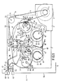
- the magnetic tape cassette device 70 as shown in Fig. 1, has a frame 1 which over a Support 2 carries a drive motor 3 rotating only in one direction.
- the output pinion 4 of the motor 3 carries a Peese 5 which is guided via a deflection roller 6 via flywheels 7 and 8 in such a way that the flywheels rotate in opposite directions.
- the flywheels 7 and 8 are mounted in the frame 1.
- the flywheel 7 is fixedly connected to a shaft 9, and the flywheel 8 is fixed to a shaft 10.
- the flywheel 7 is connected to a gear 11 and the flywheel 8 is connected to a gear 12.
- Another gear 13 is rotatably arranged on the flywheel 8 via a slip clutch coaxial with the gear 12.
- a gearwheel 14 designed as a gearwheel is constantly meshing with the gearwheel 12 on the flywheel 8.
- This gearwheel 14 is pivotable about an axis 15.
- the axis 15 carries a pivot arm 16, shown schematically in FIG. 1, on which the switching wheel 14 is rotatably mounted.
- a gear 17 meshes with the gear 11 at all times.
- This gear 17 is rotatable about a pivot axis 18 by means of a pivot arm 19 shown schematically.
- winding mandrels are rotatably mounted. These winding mandrels are firmly connected to fast winding wheels 22, 23. Game wheels 24, 25 are connected to the winding mandrels via slip clutches.
- the game wheel 25 is driven in a manner not shown by the gear wheel 12 via the ratchet wheel 14. Similarly, the game wheel 24 is driven by the gear 11 via the gear 17.
- a spring 30 always presses the bracket 26 into a starting position shown in FIG. 1.
- the bracket 26 carries two pins 28a and 29a, which are displaceable in a triangular hole 28b or a slot 29b in the frame 1.
- two longitudinally displaceable operating rods 33 and 34 are provided, which are connected to sliders 35, 36.
- These sliders 35 and 36 act on the bracket 26.
- the slide 35 is provided with a shoulder 37
- the slide 36 correspondingly carries a run-up surface 38.
- the run-up 37 and the run-up surface 38 work on a pin 39 of the bracket 26.
- the pushers 35, 36 are provided with run-on surfaces 35a, 35b or 36a, 36b, which can work on pins 74c, 74d of a head plate, not shown.
- a detection element 40 consisting of two disks 41, 42 and a connecting rod 43, is connected to the mandrels 20, 21 via slip clutches.
- a pin 44 is arranged on the disk 42 and lies within a shift fork 45.
- the shift fork 45 is arranged on a shift element 46 which is rotatable about a bearing 47.
- the switching wheel 14 bears a slightly elliptical cam 48 in the middle above.
- the switching element 46 engages over the switching wheel 14 and carries a pin 49 which can move around the cam 48 when the switching element 46 is pivoted inward when the switching wheel rotates in the direction of one Arrow 50.
- a raised extends around the cam 48 at a greater distance spiral control cam 51 protruding from the switching wheel 14.
- This control cam 51 can also cooperate with the pin 49 on the switching element 46, and always when the detection element detects that the tape is at a standstill. In this case, the pin 44 no longer presses against the shift fork 45, as a result of which the pin 49 on the shifting element 46 is no longer loaded inwards in the direction of the cam 48, but instead remains there and with continued rotation of the shift wheel 14 in the direction of the arrow 50 the outside of the cam 51 reaches. Because the control cam 51 is spiral, the switching element 46 is pivoted clockwise around its bearing 47, as a result of which the switching element 46 is pressed against a connecting element 52.
- the connecting element 52 is a double-armed lever which is pivotable about a bearing 53.
- the connecting element 52 is spring-loaded due to the action of a spring 54 in the clockwise direction. The movement of the switching element 46 thus tensions the spring 54.
- the lever arm 55 of the connecting element 52 facing away from the point of engagement of the switching element 46 carries a heart curve which belongs to a locking mechanism which can hold the head plate (not shown) in the playing position.
- EP-OS 0 138 268 PLD 83-098 EP.
- the key bars 33 and 34 are provided with key buttons 60, 61.
- a key extends parallel to the key bars 33, 34 for fast forward and reverse rod 62 for the ejection function of a magnetic tape cassette.
- a button 63 is arranged on the button bar 62.
- the key rods 33 and 34 are provided with upwardly projecting drivers 64, 65 which interact with an extension 66 of the key rod 62 for the ejection function (FIG. 2).
- the boom 66 engages on the side remote from the inside of the drive behind the front edges 67 of the drivers 64, 65.
- the front or front panel 68 of the magnetic tape cassette device is provided with openings through which the buttons 60, 61 and 63 reach, so that they can be operated from the outside 71 of the device, ie. H. are impressible.
- Fig. 2 shows a graphical representation of the interaction of the key rods 34, 35 and 62.
- the drivers 64, 65 of the key rods 33, 34 protrude upwards from the key rods 33 and 34 in the drawing according to FIG. 2.
- the arm 66 is fastened on the key rod 62, for example by spraying.
- the boom engages in front of the front edges 67 of the drivers 64, 65 and thus on the side remote from the drive.
- the boom 66 is shown transparently, so that it is easier to see how it engages in front of the front edges 67 of the drivers 64, 65.
- the two key rods 33, 34 are loaded with the aid of springs 72 in the extension direction.
- the key rod 62 is loaded and extended in a manner not shown in the extension direction, while it is retracted when the magnetic tape cassette is pushed out.
- buttons 60, 61, 63 In Fig. 3 the mutual position of the buttons 60, 61, 63 is shown when the magnetic tape cassette is pushed out, as is the state of the art today.
- the push buttons 60 and 61 can be seen extended in the illustration according to FIG. 3, while the push button 63 is pushed into the front panel 68 and disappears completely or almost completely therein. If a magnetic tape cassette is inserted into the drive, the key rod 62 pops out with its key button 63, and all three buttons 60, 61, 63 are either located equally far in front of the front of the front panel 68, or the key button 63 projects even further.
- the image shown in FIG. 4 results when the magnetic tape cassette is removed from the drive.
- the push buttons 60 and 61 are also pushed into the front panel 68, and all three push buttons 60, 61, 63 lie almost in one plane or almost completely disappeared within the device. If a cassette is inserted into the drive, the springs 72 of the key rods 33, 34 push all the key rods out for fast forward and reverse; since the drivers 64, 65 take the key rod 62 for the ejection movement via the extension 66, this key rod 62 can be dispensed with an ejection spring.
Landscapes
- Toys (AREA)
- Push-Button Switches (AREA)
- Feeding And Guiding Record Carriers (AREA)
- Casings For Electric Apparatus (AREA)
Applications Claiming Priority (2)
| Application Number | Priority Date | Filing Date | Title |
|---|---|---|---|
| DE3936076A DE3936076A1 (de) | 1989-10-28 | 1989-10-28 | Magnetbandkassettengeraet mit einem von hand bedienbaren kassettenlaufwerk |
| DE3936076 | 1989-10-28 |
Publications (3)
| Publication Number | Publication Date |
|---|---|
| EP0426236A2 true EP0426236A2 (fr) | 1991-05-08 |
| EP0426236A3 EP0426236A3 (en) | 1991-08-07 |
| EP0426236B1 EP0426236B1 (fr) | 1995-05-24 |
Family
ID=6392509
Family Applications (1)
| Application Number | Title | Priority Date | Filing Date |
|---|---|---|---|
| EP90202832A Expired - Lifetime EP0426236B1 (fr) | 1989-10-28 | 1990-10-24 | Appareil à cassette à bande magnétique avec dispositif d'entraînement de cassette commandé manuellement |
Country Status (4)
| Country | Link |
|---|---|
| EP (1) | EP0426236B1 (fr) |
| JP (1) | JP2546497Y2 (fr) |
| KR (1) | KR970002574Y1 (fr) |
| DE (2) | DE3936076A1 (fr) |
Family Cites Families (4)
| Publication number | Priority date | Publication date | Assignee | Title |
|---|---|---|---|---|
| US4026496A (en) * | 1974-08-19 | 1977-05-31 | Tokyo Denshi Kabushiki Kaisha | Automatic repeat system for magnetic tape recorders and reproducers |
| DE3042748A1 (de) * | 1980-11-13 | 1982-06-16 | Philips Patentverwaltung Gmbh, 2000 Hamburg | "magnetbandkassettengeraet mit mindestens zwei drucktasten" |
| DE3337359C1 (de) * | 1983-10-14 | 1985-01-31 | Philips Patentverwaltung Gmbh, 2000 Hamburg | Steuermechanismus fuer das Laufwerk eines Magnetbandkassettengeraetes |
| DE3672896D1 (de) * | 1985-05-23 | 1990-08-30 | Philips Patentverwaltung | Magnetbandkassettengeraet mit zwei tastenknoepfen. |
-
1989
- 1989-10-28 DE DE3936076A patent/DE3936076A1/de not_active Withdrawn
-
1990
- 1990-10-19 KR KR2019900015899U patent/KR970002574Y1/ko not_active Expired - Fee Related
- 1990-10-24 EP EP90202832A patent/EP0426236B1/fr not_active Expired - Lifetime
- 1990-10-24 DE DE59009126T patent/DE59009126D1/de not_active Expired - Fee Related
- 1990-10-25 JP JP1990111167U patent/JP2546497Y2/ja not_active Expired - Lifetime
Also Published As
| Publication number | Publication date |
|---|---|
| DE3936076A1 (de) | 1991-05-02 |
| DE59009126D1 (de) | 1995-06-29 |
| KR970002574Y1 (ko) | 1997-03-26 |
| JP2546497Y2 (ja) | 1997-09-03 |
| JPH0371432U (fr) | 1991-07-19 |
| EP0426236A3 (en) | 1991-08-07 |
| EP0426236B1 (fr) | 1995-05-24 |
Similar Documents
| Publication | Publication Date | Title |
|---|---|---|
| DE2515082B2 (de) | Betriebsartumschaltung bei einem Kassettenrekorder für selbsttätigen Endeinzug und Auswurf der Kassette | |
| DE2904992C2 (fr) | ||
| DE2942404C2 (fr) | ||
| DE2839660C2 (fr) | ||
| EP0426236B1 (fr) | Appareil à cassette à bande magnétique avec dispositif d'entraînement de cassette commandé manuellement | |
| DE3447539C2 (fr) | ||
| EP0300187B1 (fr) | Mécanisme d'entraînement pour un appareil à cassette à bande magnétique | |
| DE2611565A1 (de) | Kassettentonbandgeraet | |
| DE2841903C3 (de) | Betriebsarteneinstellmechanismus für ein Bandgerät | |
| DE3401691C1 (de) | Schaltmechanismus fuer das Laufwerk eines Magnetbandkassettengeraetes | |
| DE2233127B2 (fr) | ||
| EP0150078B1 (fr) | Dispositif de commutation dans un appareil à cassette à bande magnétique | |
| DE3312134C1 (de) | Vorrichtung an dem reversierenden Laufwerk eines Magnetbandkassettengerätes | |
| EP0667611B1 (fr) | Appareil pour bande magnétique à cassette pour déroulement reversible des cassettes à bande magnétique | |
| DE3016005A1 (de) | Stehbildkamera mit einer filmtransport- und einer filmrueckspulhandhabe | |
| DE580027C (de) | Rechenmaschine mit selbsttaetiger Multipliziervorrichtung | |
| DE3637323C1 (de) | Schaltmechanismus fuer ein Magnetband-Kassettengeraet | |
| DE976434C (de) | Magnettongeraet mit Drucktasteneinschaltung der verschiedenen Antriebsarten | |
| DE2711463A1 (de) | Vorrichtung zur automatischen, mindestens einmaligen repetition bei einem bandspeichergeraet | |
| DE4032634C2 (fr) | ||
| EP0319646A1 (fr) | Mécanisme de communication pour changer le sens de défilement de la bande d'un magnétophone à cassettes fonctionnant en mode "reverse" | |
| DE4032635C2 (fr) | ||
| EP0138268A2 (fr) | Mécanisme de commande de l'entraînement d'un appareil à cassette à bande magnétique | |
| DE2430977C3 (de) | Magnetbandgerät | |
| DE2247494C3 (de) | Magnetisches Tonaufzeichnungs- und Wiedergabegerät für Endlos - Bandkassetten |
Legal Events
| Date | Code | Title | Description |
|---|---|---|---|
| PUAI | Public reference made under article 153(3) epc to a published international application that has entered the european phase |
Free format text: ORIGINAL CODE: 0009012 |
|
| AK | Designated contracting states |
Kind code of ref document: A2 Designated state(s): DE FR GB IT |
|
| PUAL | Search report despatched |
Free format text: ORIGINAL CODE: 0009013 |
|
| AK | Designated contracting states |
Kind code of ref document: A3 Designated state(s): DE FR GB IT |
|
| 17P | Request for examination filed |
Effective date: 19920305 |
|
| 17Q | First examination report despatched |
Effective date: 19940829 |
|
| GRAA | (expected) grant |
Free format text: ORIGINAL CODE: 0009210 |
|
| AK | Designated contracting states |
Kind code of ref document: B1 Designated state(s): DE FR GB IT |
|
| REF | Corresponds to: |
Ref document number: 59009126 Country of ref document: DE Date of ref document: 19950629 |
|
| ITF | It: translation for a ep patent filed | ||
| GBT | Gb: translation of ep patent filed (gb section 77(6)(a)/1977) |
Effective date: 19950726 |
|
| ET | Fr: translation filed | ||
| PLBE | No opposition filed within time limit |
Free format text: ORIGINAL CODE: 0009261 |
|
| STAA | Information on the status of an ep patent application or granted ep patent |
Free format text: STATUS: NO OPPOSITION FILED WITHIN TIME LIMIT |
|
| 26N | No opposition filed | ||
| PGFP | Annual fee paid to national office [announced via postgrant information from national office to epo] |
Ref country code: GB Payment date: 19970930 Year of fee payment: 8 |
|
| PGFP | Annual fee paid to national office [announced via postgrant information from national office to epo] |
Ref country code: FR Payment date: 19971021 Year of fee payment: 8 |
|
| REG | Reference to a national code |
Ref country code: FR Ref legal event code: CD |
|
| PG25 | Lapsed in a contracting state [announced via postgrant information from national office to epo] |
Ref country code: GB Free format text: LAPSE BECAUSE OF NON-PAYMENT OF DUE FEES Effective date: 19981024 |
|
| GBPC | Gb: european patent ceased through non-payment of renewal fee |
Effective date: 19981024 |
|
| PG25 | Lapsed in a contracting state [announced via postgrant information from national office to epo] |
Ref country code: FR Free format text: LAPSE BECAUSE OF NON-PAYMENT OF DUE FEES Effective date: 19990630 |
|
| REG | Reference to a national code |
Ref country code: FR Ref legal event code: ST |
|
| PGFP | Annual fee paid to national office [announced via postgrant information from national office to epo] |
Ref country code: DE Payment date: 19991215 Year of fee payment: 10 |
|
| PG25 | Lapsed in a contracting state [announced via postgrant information from national office to epo] |
Ref country code: DE Free format text: LAPSE BECAUSE OF NON-PAYMENT OF DUE FEES Effective date: 20010703 |
|
| PG25 | Lapsed in a contracting state [announced via postgrant information from national office to epo] |
Ref country code: IT Free format text: LAPSE BECAUSE OF NON-PAYMENT OF DUE FEES;WARNING: LAPSES OF ITALIAN PATENTS WITH EFFECTIVE DATE BEFORE 2007 MAY HAVE OCCURRED AT ANY TIME BEFORE 2007. THE CORRECT EFFECTIVE DATE MAY BE DIFFERENT FROM THE ONE RECORDED. Effective date: 20051024 |