EP0426242A1 - Werbevorrichtung mit Deflektor - Google Patents
Werbevorrichtung mit Deflektor Download PDFInfo
- Publication number
- EP0426242A1 EP0426242A1 EP90202847A EP90202847A EP0426242A1 EP 0426242 A1 EP0426242 A1 EP 0426242A1 EP 90202847 A EP90202847 A EP 90202847A EP 90202847 A EP90202847 A EP 90202847A EP 0426242 A1 EP0426242 A1 EP 0426242A1
- Authority
- EP
- European Patent Office
- Prior art keywords
- light
- lighting system
- display lighting
- wall
- light source
- Prior art date
- Legal status (The legal status is an assumption and is not a legal conclusion. Google has not performed a legal analysis and makes no representation as to the accuracy of the status listed.)
- Withdrawn
Links
- 238000009826 distribution Methods 0.000 claims description 6
- 238000009827 uniform distribution Methods 0.000 description 4
- 238000009792 diffusion process Methods 0.000 description 2
- 239000000853 adhesive Substances 0.000 description 1
- 230000001070 adhesive effect Effects 0.000 description 1
- 230000003247 decreasing effect Effects 0.000 description 1
- 230000000694 effects Effects 0.000 description 1
- 239000000463 material Substances 0.000 description 1
- 230000007704 transition Effects 0.000 description 1
Images
Classifications
-
- G—PHYSICS
- G09—EDUCATION; CRYPTOGRAPHY; DISPLAY; ADVERTISING; SEALS
- G09F—DISPLAYING; ADVERTISING; SIGNS; LABELS OR NAME-PLATES; SEALS
- G09F13/00—Illuminated signs; Luminous advertising
- G09F13/04—Signs, boards or panels, illuminated from behind the insignia
- G09F13/14—Arrangements of reflectors therein
-
- G—PHYSICS
- G09—EDUCATION; CRYPTOGRAPHY; DISPLAY; ADVERTISING; SEALS
- G09F—DISPLAYING; ADVERTISING; SIGNS; LABELS OR NAME-PLATES; SEALS
- G09F13/00—Illuminated signs; Luminous advertising
- G09F13/04—Signs, boards or panels, illuminated from behind the insignia
- G09F13/0418—Constructional details
- G09F13/0422—Reflectors
-
- G—PHYSICS
- G09—EDUCATION; CRYPTOGRAPHY; DISPLAY; ADVERTISING; SEALS
- G09F—DISPLAYING; ADVERTISING; SIGNS; LABELS OR NAME-PLATES; SEALS
- G09F13/00—Illuminated signs; Luminous advertising
- G09F13/04—Signs, boards or panels, illuminated from behind the insignia
- G09F13/14—Arrangements of reflectors therein
- G09F2013/145—Arrangements of reflectors therein curved reflectors
Definitions
- the invention relates to a display lighting system comprising a light box having at least one light-transmitting wall, to which an image to be displayed can be secured.
- Such display lighting systems are e.g. present on buildings or along motorways, whereby generally conspicuous advertising displays in the shape of a text and/or an illustration will be quite noticeable as a result of their being well placed and lighted.
- the object of the invention is to provide a (display) lighting system, wherein a more uniform distribution of the amount of light to be distributed over the area of the light-transmitting wall with the possible image is achieved by simple measures, without the system gaining in thickness or the total weight of the system increasing to a significant degree.
- the display lighting system mentioned in the preamble is according to the invention characterized in that said display lighting system comprises deflection means provided between the light source and the light-transmitting wall.
- the advantage of using deflection means in the display lighting system according to the invention is that it is prevented that light beams directly emanating from the light source reach the observer's eye. By preventing that said direct light beams are observed it is achieved that light beams emanating from the light source do not reach the observer's eye before they have been reflected in the light box one or more times, as a result of which a more uniform distribution of the light intensity over the light-transmitting wall is obtained, and in particular those parts of the light-transmitting wall which are located at a relatively larger distance from the light source are illuminated better, whilst on the contrary the light intensity on a part of the light-transmitting wall located close to the light source will be decreased.
- One embodiment of the display lighting system is according to the invention characterized in that the deflection means are equipped with a carrier, on which conical fins are mounted, in order that the light source is at least partially hidden from view by the carrier with the fins.
- this embodiment of the display lighting system according to the invention effects a desirable, most gradual, and substantially imperceptable variation in the light intensity on the light-transmitting wall, in particular near the light source.
- a second embodiment of the display lighting system is according to the invention characterized in that the conical fins taper off to a point.
- This second embodiment of the display lighting system according to the invention shows a substantially optimal gradual transition of light near the light source on the light-transmitting wall.
- a third embodiment of the display lighting system is according to the invention characterized in that the fins are curved in a direction opposite to the direction of the light source.
- the advantage of this embodiment of the display lighting system according to the invention is that the curved fins improve the diffusion of the light emanating from the light source, with the additional advantage that this results in a more uniform distribution of light.
- a fourth embodiment of the display lighting system is according to the invention characterized in that the carrier has a width a, and that each fin has a base b and a height h, and that the parameters a, b and h have been selected such, that with given dimensions of the light source a distribution of the intensity of the light over the light-transmitting wall which is as uniform as possible is achieved.
- the advantage of this embodiment of the display lighting system according to the invention is that in practice the vitally important parameters a, b and h will be determined empirically, in order to obtain an optimum distribution of light.
- the selection of said parameters in a given case at the same time determines the number of fins per unit of length, which is required in order to achieve an optimum distribution of light.
- a fifth possible embodiment of the display lighting system is according to the invention characterized in that the light source comprises a point source, and that the deflection means with the fins mounted on the carrier are star-shaped.
- This embodiment of the display lighting system according to the invention has appeared to be advantageous in practice in case the point source is an incandescent lamp.
- a sixth possible embodiment of the display lighting system is according to the invention characterized in that the light source comprises a line source and that the deflection means are provided with a carrier in the shape of a longitudinal carrier, the fins being mounted on said longitudinal carrier.
- This embodiment of the display lighting system according to the invention has appeared to be advantageous in practice in case the line source is a fluorescent tube.
- a seventh possible embodiment of the display lighting system is according to the invention characterized in that the display system has a curved reflecting inner wall accommodated in the light box, and that the light-transmitting wall is made such that it transmits part of the light from the light source that falls thereon and reflects the remaining part onto the reflecting inner wall.
- the advantage of this seventh embodiment of the display lighting system according to the invention is that the number of internal reflections in the light source will increase and, because the rear wall is curved, in particular the number of internal reflections at a relatively large distance from the light source in the light box will increase, which will further improve the uniformity of the lighting in the display lighting system.
- An eighth possible embodiment of the display lighting system is according to the invention characterized in that an opening has been left clear near the edge of the light box, at the location where the side of the light-transmitting wall and the end of the curved reflecting inner wall approach one another.
- the advantage of this seventh embodiment of the display lighting system according to the invention is that a possibility has been created to couple the light box with further light boxes, to form a display lighting system having an increased area, whereby in particular along the edges of the individual light boxes that are coupled a good and uniform distribution of light is ensured, because of the opening that is present between adjacent light boxes.
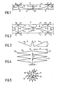
- FIGS 1 and 2 illustrate possible embodiments of a display lighting system 1.
- Said display lighting system 1 comprises a light box 2, which is provided with at least one light-transmitting wall 3, and possibly a rear wall 4 and side walls 5.
- the cross-sections of the display lighting system 1 shown in Figures 1 and 2 have one or more light sources 6.
- the light source 6 may contain one or several point sources, e.g. in the shape of an incandescent lamp, or a line source, e.g. in the shape of one or more fluorescent tubes.
- an image to be displayed will be secured to the inner side of the light-transmitting wall, e.g. by means of an adhesive.
- the possible embodiment of the display lighting system 2 illustrated in cross-section in Figure 2 has two light-transmitting walls 3, to which two different images to be displayed can be secured, if required.
- Deflection means 7 are provided between the light source 6 and the light-transmitting wall 3. The deflection means 7 prevent that light beams directly emanating from the light source 6 reach the light-transmitting wall directly.
- Figure 3 shows an enlarged cross-section of a possible embodiment of the deflection means 7.
- Figure 4 shows the front elevational view of the deflection means 7 illustrated in Figure 3.
- the deflection means 7 are provided with fins 8, which are mounted on a carrier 9.
- the embodiment illustrated in Figure 4 has a carrier 9 in the shape of a longitudinal carrier.
- the light source will be a fluorescent tube.
- the fins 8 are slightly curved, in the direction of the wall 3.
- the fins 8 will generally taper off, e.g. to a point 10.
- the carrier 9 is disc-shaped, and the deflection means 7 are star-shaped, with fins 8 which will taper off to a point 10.
- This embodiment is excellently suited for being used together with a point source in the shape of an incandescent lamp.
- the deflection means 7 is best explained with reference to Figures 1 and 2, in which the light box 2 of the display lighting system 1 has one or more reflecting inner walls 11. Said inner wall 11 is curved and may be in one piece, as is illustrated in Figure 1, or be assembled of two separate parts, as is illustrated in the embodiment of Figure 2. The advantage of the latter embodiment is that in principle one light source 6 will be sufficient for lighting the images present on the light-transmitting walls 3.
- Either the light emanating from the light source 6 will first fall on the reflecting inner wall 11, or fall substantially entirely on the reflecting means 7, and then be reflected from there to the reflecting inner wall 11. After a light beam has been reflected on the inner wall 11 said light beam will fall on the light-transmitting wall 3.
- Said light-transmitting wall 3 is designed to transmit part of the light that falls thereon and reflect the remaining part back onto the reflecting inner wall 11. Thereby multiple reflections take place between the light-transmitting wall 3 and the reflecting wall 11, which directs said light beams to the edge 12 of the light box 2, so that also these edges 12 are illuminated well.
- the edges 12 are illustrated by means of thicker lines in Figures 1 and 2. The multiple internal reflections contribute towards the uniformity of the intensity of the lighting over the light-transmitting wall 3.
- the curved reflecting inner wall 3 will be locally provided with a protrusion 15, at the location where said inner wall is nearest to the light source 6, said protrusion scattering the light that falls thereon in the light box 2.
- a 3 mm
- b 4 mm
- h 13.5 mm.
- the dimension a of the carrier 9 may amount to twice the thickness of the material.
- the carrier 9 is formed by two flanged ends of the fins 8, which may be attached together in a simple manner, e.g. by spotwelding.
- An opening 13 has been left clear near the edge 12 of the light box 2, between the light-transmitting wall 3 and the reflecting inner wall 11. Via said openings 13 the light from the light box 2 can enter adjacent light boxes 14. On the other hand the light from a light source (not shown) in the adjacent light box 14 can be emitted, via the opening 13, to the light box 2. As a result of this a good uniform light yield and distribution of light is ensured at the location of the edges 12 of the individual light boxes 2 and 14.
Landscapes
- Physics & Mathematics (AREA)
- General Physics & Mathematics (AREA)
- Engineering & Computer Science (AREA)
- Theoretical Computer Science (AREA)
- Illuminated Signs And Luminous Advertising (AREA)
Applications Claiming Priority (2)
| Application Number | Priority Date | Filing Date | Title |
|---|---|---|---|
| NL8902677 | 1989-10-30 | ||
| NL8902677A NL8902677A (nl) | 1989-10-30 | 1989-10-30 | Lichtreklamesysteem met deflector. |
Publications (1)
| Publication Number | Publication Date |
|---|---|
| EP0426242A1 true EP0426242A1 (de) | 1991-05-08 |
Family
ID=19855533
Family Applications (1)
| Application Number | Title | Priority Date | Filing Date |
|---|---|---|---|
| EP90202847A Withdrawn EP0426242A1 (de) | 1989-10-30 | 1990-10-25 | Werbevorrichtung mit Deflektor |
Country Status (2)
| Country | Link |
|---|---|
| EP (1) | EP0426242A1 (de) |
| NL (1) | NL8902677A (de) |
Cited By (5)
| Publication number | Priority date | Publication date | Assignee | Title |
|---|---|---|---|---|
| DE19520487A1 (de) * | 1995-06-03 | 1996-12-05 | M & V Reklametechnik Schoening | Leuchtvitrine |
| DE29609245U1 (de) * | 1996-05-23 | 1997-09-25 | Trautwein Gmbh & Co, 45659 Recklinghausen | Werbeanordnung |
| FR2797083A1 (fr) * | 1999-07-26 | 2001-02-02 | Bernard Duval | Panneau lumineux |
| ES2183731A1 (es) * | 2001-07-18 | 2003-03-16 | Perez Agustin Molla | Estructura para vallas publicitarias |
| WO2006050849A3 (de) * | 2004-11-09 | 2006-09-28 | Wall Ag | Werbevitrine |
Citations (3)
| Publication number | Priority date | Publication date | Assignee | Title |
|---|---|---|---|---|
| EP0050267A2 (de) * | 1980-10-18 | 1982-04-28 | Paul Albrecht | Vorrichtung zum Hinterleuchten grossflächiger Anzeigetafeln |
| DE3033462A1 (de) * | 1980-09-05 | 1982-04-29 | Achim Dipl.-Ing. Dr.-Ing. 1000 Berlin Willing | Beleuchtungsvorrichtung zur hinterleuchtung eines transparentes mit hoher gleichmaessigkeit |
| AT368266B (de) * | 1979-09-03 | 1982-09-27 | Berndeisel & Co Johann | Werbeleuchte |
-
1989
- 1989-10-30 NL NL8902677A patent/NL8902677A/nl not_active Application Discontinuation
-
1990
- 1990-10-25 EP EP90202847A patent/EP0426242A1/de not_active Withdrawn
Patent Citations (3)
| Publication number | Priority date | Publication date | Assignee | Title |
|---|---|---|---|---|
| AT368266B (de) * | 1979-09-03 | 1982-09-27 | Berndeisel & Co Johann | Werbeleuchte |
| DE3033462A1 (de) * | 1980-09-05 | 1982-04-29 | Achim Dipl.-Ing. Dr.-Ing. 1000 Berlin Willing | Beleuchtungsvorrichtung zur hinterleuchtung eines transparentes mit hoher gleichmaessigkeit |
| EP0050267A2 (de) * | 1980-10-18 | 1982-04-28 | Paul Albrecht | Vorrichtung zum Hinterleuchten grossflächiger Anzeigetafeln |
Cited By (5)
| Publication number | Priority date | Publication date | Assignee | Title |
|---|---|---|---|---|
| DE19520487A1 (de) * | 1995-06-03 | 1996-12-05 | M & V Reklametechnik Schoening | Leuchtvitrine |
| DE29609245U1 (de) * | 1996-05-23 | 1997-09-25 | Trautwein Gmbh & Co, 45659 Recklinghausen | Werbeanordnung |
| FR2797083A1 (fr) * | 1999-07-26 | 2001-02-02 | Bernard Duval | Panneau lumineux |
| ES2183731A1 (es) * | 2001-07-18 | 2003-03-16 | Perez Agustin Molla | Estructura para vallas publicitarias |
| WO2006050849A3 (de) * | 2004-11-09 | 2006-09-28 | Wall Ag | Werbevitrine |
Also Published As
| Publication number | Publication date |
|---|---|
| NL8902677A (nl) | 1991-05-16 |
Similar Documents
| Publication | Publication Date | Title |
|---|---|---|
| DE69318980T2 (de) | Schauschrank und ein mit linsen ausgerüstetes lichtsystem dafür | |
| US4811507A (en) | Apparatus for the display of illuminated translucent documents | |
| US6382822B1 (en) | Vehicular lamp | |
| JP3093778B2 (ja) | 照明装置 | |
| US20070230212A1 (en) | Shelving illumination element | |
| US6334690B1 (en) | Surface light source device of side light type and liquid crystal display | |
| US7164836B2 (en) | Light-guide lights suitable for use in illuminated displays | |
| US4794492A (en) | Illuminated board | |
| US5134553A (en) | Illuminating device | |
| US5722747A (en) | Merchandising display | |
| JPH10255532A (ja) | 照明用光源 | |
| JP2001503189A (ja) | 照明付表示システムの改良 | |
| WO1991005972A1 (en) | Light fittings | |
| US5600909A (en) | Illuminated changeable message display | |
| NL8902677A (nl) | Lichtreklamesysteem met deflector. | |
| EP0080852B1 (de) | Anzeigeanordnungen | |
| DE4305208C2 (de) | Beleuchtbare Vitrine | |
| JP4733891B2 (ja) | 発光体のための防眩透明スクリーン | |
| AU702512B2 (en) | Display and indicating panel | |
| EP0229863B1 (de) | Lichtplatte | |
| WO2004031818A2 (en) | Light source assembly and light-guide light suitable for an illuminated display | |
| EP0866438B1 (de) | Verkehrszeichen | |
| US6437763B1 (en) | Panel for displaying messages by light spots | |
| JPH11213230A (ja) | 商品若しくは商品見本の照明構造 | |
| US4559731A (en) | Illuminated sign construction |
Legal Events
| Date | Code | Title | Description |
|---|---|---|---|
| PUAI | Public reference made under article 153(3) epc to a published international application that has entered the european phase |
Free format text: ORIGINAL CODE: 0009012 |
|
| 17P | Request for examination filed |
Effective date: 19901025 |
|
| AK | Designated contracting states |
Kind code of ref document: A1 Designated state(s): AT BE CH DE DK ES FR GB GR IT LI LU NL SE |
|
| 17Q | First examination report despatched |
Effective date: 19930407 |
|
| STAA | Information on the status of an ep patent application or granted ep patent |
Free format text: STATUS: THE APPLICATION IS DEEMED TO BE WITHDRAWN |
|
| 18D | Application deemed to be withdrawn |
Effective date: 19930818 |