EP0426256B1 - Apparat zum kontrollierten Zuführen von blattförmigen Produkten in einer Zusammentrag- oder Verpackungsmaschine - Google Patents
Apparat zum kontrollierten Zuführen von blattförmigen Produkten in einer Zusammentrag- oder Verpackungsmaschine Download PDFInfo
- Publication number
- EP0426256B1 EP0426256B1 EP90202876A EP90202876A EP0426256B1 EP 0426256 B1 EP0426256 B1 EP 0426256B1 EP 90202876 A EP90202876 A EP 90202876A EP 90202876 A EP90202876 A EP 90202876A EP 0426256 B1 EP0426256 B1 EP 0426256B1
- Authority
- EP
- European Patent Office
- Prior art keywords
- sheet form
- push
- accompanying
- bar conveyor
- products
- Prior art date
- Legal status (The legal status is an assumption and is not a legal conclusion. Google has not performed a legal analysis and makes no representation as to the accuracy of the status listed.)
- Expired - Lifetime
Links
Images
Classifications
-
- B—PERFORMING OPERATIONS; TRANSPORTING
- B65—CONVEYING; PACKING; STORING; HANDLING THIN OR FILAMENTARY MATERIAL
- B65H—HANDLING THIN OR FILAMENTARY MATERIAL, e.g. SHEETS, WEBS, CABLES
- B65H39/00—Associating, collating, or gathering articles or webs
- B65H39/02—Associating,collating or gathering articles from several sources
- B65H39/04—Associating,collating or gathering articles from several sources from piles
- B65H39/043—Associating,collating or gathering articles from several sources from piles the piles being disposed in juxtaposed carriers
Definitions
- the present invention relates to an apparatus for the controlled feeding of products in sheet form in a collating or packaging machine according to the preamble of claim 1.
- Such feeding apparatuses are constituted, e.g., by drawers or magazine portions inside which the product in sheet form is stored, arranged parallel to, or in-line with, the above said conveyor, and drawing/feeding devices, called “sheet feeders".
- sheet feeders drawing/feeding devices
- Such devices determine, in combination, the drawing and advancement of individual sheets, or sheet signatures or other products essentially in -- either folded or not folded -- sheet form, on top of the push-bar feeder, such as to form a predetermined succession or collection of groups of products.
- a similar operation of collection or assemblage of more or less different products in sheet form is also carried out on "packaging machines", in which to the base product, e.g., fed by another suitable feeder device purposely provided upstream the machine, one or more insert(s) has(have) to be added, wherein each of said inserts can be constituted by one or more sheet(s), sheet bundle(s), or other similar product(s).
- such a feeding of the product in sheet form in free-falling mode additionally involves, with varying collating or packaging speeds, the consequent change of mutual timing of the feeder device arranged at 90° to, or in-line with, the push-bar conveyor and the same push-bar conveyor. This need arises in that the correct equilibrium has to he established each time, between the processing speed and the speed of feeding of the products in sheet form.
- US-A-4 865 304 discloses an apparatus for the controlled feeding of products in sheet form in a packaging machine according to the preamble of claim 1.
- the purpose of the instant invention is of getting rid of such problems relevant to the need of timing setting when the processing speed varies, and deriving from the presence of collating or packaging feeding stations in succession after each other, in which the individual products in sheet form are fed under free-falling conditions between the feeder device and the push-bar conveyor.
- This purpose according to the present invention is achieved by providing an apparatus for the controlled feeding of products in sheet form in a collating or packaging machine according to claim 1.
- an apparatus provided with a structure according to the present invention by eliminating the air cushion, i.e., the free falling of the product in sheet form, enables said product to be correctly and constantly placed on top of said push-bar conveyor, or in an equivalent way above similar elements in sheet form previously placed above the push-bar conveyor.
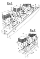
- an apparatus for the controlled feeding of products in sheet form is associated with a collating or packaging machine, only partially shown, which comprises a base framework 11 on which there are essentially installed a magazine portion 12 containing the products in sheet form 13 to be fed, a drawing/advancement unit, generally indicated with the reference numeral 14, for drawing one of said products in sheet form 13, and a push-bar conveyor which is arranged between side walls 15, which define a channel.
- said conveyor is only indicated by means of its push-bar elements 16 and the drive chain 17 which drives said push-bar elements.
- a drawing/advancement unit 14 is shown, which is arranged at 90° to the underlying push-bar conveyor; however, in an at all equivalent way, such an unit could be arranged directly in-line to the channel or push-bar conveyor.
- Such a drawing/advancement unit is exemplified by revolving elements 18 with associated belts 19 which draw at least one product in sheet form 13 from the magazine partion 12 and -- by cooperating with further associated belts 20 -- cause said product in sheet form 13 to advance towards the push-bar conveyor.
- the revolving elements 18 are driven to revolve by a central shaft 21 actuated in its turn by means of a transmission 22, such as, e.g., a cogged belt, which transmits to said central shaft the motion drawn from the motor means ( per se known, and not shown herein) which drive the push-bar conveyor. In that way, a mechanical timing between the push-bar conveyor 16, 17 and the drawing/advancement unit 14 is accomplished.
- an apparatus which carries out the controlled feeding of the products in sheet form 13.
- Such an apparatus essentially comprises at least one accompanying element which accompanies said drawn product in sheet form 13 during its movement.
- Such a sheet product accompanying element is, as said, interposed, and is actuated by actuation means which cause it to intervene once that the product in sheet form 13, drawn from the magazine portion 12, has left the drawing/advancement unit 14 and must be placed in the nearby of the push-bar conveyor 16, 17.
- FIG. 1 The exemplifying form of practical embodiment shown in Figures 1 and 2 exactly corresponds to the scheme shown in figure 4 and shows an accompanying element 35 constituted by a flexible or rigid brush or plate.
- a lever 26 is hinged in 25 to the framework 11 and in 27 onto a first end of a drive connecting rod 28, whose second end is hinged in 29 to a crank 30, accomplished by means of a first a cogged wheel constrained to the framework 11, however free of revolving, by being actuated by a cogged belt 31 inmeshing with a second cogged pulley 32 rigidly keyed on the central shaft 21.
- a rigid and synchronous mechanical transmission is created between the motor means which drives the push-bar conveyor, and the motor means which drive the drawing/advancement means and the several accompanying elements.
- a means could be provided for adjusting the position of the hinge 27 which links the connecting rod 28 and the lever 26.
- the adjustment could be achieved by means of a sleeve provided with an inner screw-threading and inmeshing, which possibility of position adjustment, on the screw-threaded provided on at least one portion of the lever 26.
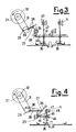
- Figure 3 shows an exemplifying form of practical embodiment in which onto the crank 30 the drive connecting rod 28 and lever 26 are replaced by two lever partions 38 arranged at a square angle to each other and at their other end are hinged in 25 onto the frame 11. Said two lever portions 38 are rigidly linked, at their other side relatively to the hinge pin 25, with a further first lever portion 39 whose free end is hinged relatively to at least one second lever portion 40.
- Figure 4 shows an apparatus according to the present invention, which partially resembles the just disclosed apparatus as regards the accompanying element 35.
- the lever 26 extends beyond the hinge pin 25, in a further lever portion 44 bearing at its free end a slot 45 inside which a pin 46 enters with possibility of free sliding.
- the pin 46 is integral with a rod, or extension 47, which at one of its ends bears, as said, the accompanying element 35 and at its other end is slidingly guided inside a guide element 48 integral with the framework 11.
- the guide element 48 is arranged substantially vertical to the accompanying element 35 and therefore to the plane of the push-bar conveyor 16, 17. Also in this case, an essentially vertical movement of the accompanying element is achieved.
- such a rigid brush can be constituted by a shaped metal plate 35, interacting with the product in sheet form, provided with an invitation edge facing upwards at its end opposite to the drawing/advancement unit 14.
- An apparatus independently from its preferred exemplifying form of practical embodiment, determines an oscillatory movement of the accompanying element, which is timed relatively to the advancement of the product in sheet form 13 leaving the drawing/advancement unit 14.
- the accompanying element is raised, so as to facilitate said product in sheet form to enter the free gap defined between it and the underlying push bar conveyor, thus the arising of any contrast problems being prevented at all.
- the accompanying element driven by the relevant actuation means moves downwards or rocks, thus causing the mechanical accompanying to take place of the product in sheet form 13 to the underlying surface which can either be a further, previously fed, element, or just the surface od the push bar conveyor.
- the presence of the accompanying element which lowers the product in sheet form does not allow the air cushion experienced in the apparatuses known from the prior art, to be formed.
- Such a lowered or rocked position is maintained throughout the step during which the product in sheet form is pushed out from the drawing/advancement unit 14, so as to secure that the product in sheet form will be perfectly deposited on the underlying surface and will take the same speed of advancement as of the push bar conveyer and/or of the possible product previously deposited on the same push bar conveyor.
Landscapes
- Collation Of Sheets And Webs (AREA)
- Containers And Plastic Fillers For Packaging (AREA)
- Packaging Of Special Articles (AREA)
- Making Paper Articles (AREA)
- Separation, Sorting, Adjustment, Or Bending Of Sheets To Be Conveyed (AREA)
- Feeding Of Articles By Means Other Than Belts Or Rollers (AREA)
- Controlling Rewinding, Feeding, Winding, Or Abnormalities Of Webs (AREA)
- Replacement Of Web Rolls (AREA)
- Pile Receivers (AREA)
Claims (8)
- Apparat zum kontrollierten Zuführen von blattförmigen Produkten in eine Zusammentrag- oder Verpackungsmaschine umfassend einen Rahmen (11), auf welchem ein Magazin (12), welches die zuzuführenden Produkte in Form von Blättern (13) enthält, installiert ist, eine Förder-/Vorschubeinheit (14) zum Herausziehen eines der Produkte in Form von Blättern (13) aus dem Magazin und zum Fördern desselben zu einem Schubstabförderer (16,17), an dessen Oberseite wenigstens eines der Produkte in Form von Blättern (13) welches derart abgezogen wird, placiert wird, wobei wenigstens ein Begleitelement (35) vorgesehen ist, welches die Arbeit des Begleitens des derart abgezogenen Produktes in Form vor Blättern (13) zur Oberseite des Schubstabförderers (16,17) verrichtet, wobei das wenigstens eine Begleitelement zwischen der Förder-/Vorschubeinheit (14) und dem Schubstäbförderer (16,17) gelagert ist, wobei weiters Betätigungsmittel (21,22,31,32) vorgesehen sind, weiche Betätigungsmittel die Arbeit des Betätigens des wenigstens einen Begleitelementes verrichten und immer dann eingreifen, wenn das Produkt in Form von Blättern (13) die Förder-/Vorschubeinheit (14) verlassen hat und im Bereich des Schubstabförderers (16,17) placiert ist, wobei zwischen den Betätigungsmitteln und dem wenigstens einen Begleitelement ein Hebel (26,38,39,40,44) vorgesehen ist, welcher an seinem einen Ende an dem Rahmen angelenkt ist und zu einer oszillierenden Bewegung angetrieben ist, wobei zwischen dem Hebel und den Betätigungsmitteln weiters eine Triebstange (28,38) vorgesehen ist, dadurch gekennzeichnet, daß die Triebstange (28,38) weiters an einer Kurbel (30) angelenkt ist, welche zu einer umlaufenden Bewegung durch die Betätigungsmittel (21,22,31,32), welche der Förder-/Vorschubeinheit (14) zugeordnet sind, angetrieben ist, und daß der Hebel (26) an der Seite, an welcher er an dem Rahmen (11) angelenkt ist (bei 25), sich in einen weiteren Hebelteil (39,40,44) erstreckt, welcher mit einem Fortsatz (42,47) des wenigstens einen Begleitelementes (35) durch ein erstes Führungselement (41,45) und ein Bolzenelement (40,46), welches alternativ an dem weiteren Hebelteil (39,40,44) und Fortsatz (42,47) vorgesehen ist und damit wechselwirkt, verbunden ist, wobei der Fortsatz (42,47) in einem zweiten, gemeinsam mit dem Rahmen (11) ausgebildeten Führungselement (43,48) gleitet und senkrecht zu der auf die durch den Schubstabförderer (16,17) definierten Ebene angeordnet ist.
- Apparat nach Anspruch 1, dadurch gekennzeichnet, daß der weitere Hebelteil einen ersten Hebelteil (39), welcher an seinem freien Ende angelenkt einen zweiten Hebelteil (40) als Bolzenteil trägt, welcher in das an dem Fortsatz (42) des wenigstens einen Begleitelementes (35) vorgesehene erste Führungselement (41) eintritt.
- Apparat nach Anspruch 1, dadurch gekennzeichnet, daß der weitere Hebelteil (44) an seinem freien Ende einen Schlitz (45) als erstes Führungselement aufweist, in welchem ein Bolzen (46) gleitet, welcher Bolzen (46) gemeinsam mit dem Fortsatz (47) des wenigstens einen Begleitelementes (35) ausgebildet ist.
- Apparat nach Anspruch 1, dadurch gekennzeichnet, daß das wenigstens eine Begleitelement (35) eine flexible Bürste ist.
- Apparat nach Anspruch 1, dadurch gekennzeichnet, daß das wenigstens eine Begleitelement (35) eine starre Bürste ist.
- Apparat nach Anspruch 1, dadurch gekennzeichnet, daß das wenigstens eine Begleitelement (35) eine geformte Metallplatte ist.
- Apparat nach Anspruch 6, dadurch gekennzeichnet, daß die geformte Metallplatte im wesentlichen parallel zu der Ebene des Schubstabförderers (16,17) angeordnet ist und eine nach oben gerichtete Kante an ihrem Ende aufweist, welches der Förder-/Vorschubeinheit (14) gegenüberliegt.
- Apparat nach Anspruch 1, dadurch gekennzeichnet, daß wenigstens ein Produkt-Begleitelement (35) mit Einstellmitteln zum Einstellen der Position desselben in bezug auf die Betätigungsmittel vorgesehen ist.
Applications Claiming Priority (2)
| Application Number | Priority Date | Filing Date | Title |
|---|---|---|---|
| IT22032U IT219167Z2 (it) | 1989-11-02 | 1989-11-02 | Apparecchiatura per l'alimentazione controllata di prodotti in foglio in una macchina collazionatrice o confezionatrice |
| IT2203289U | 1989-11-02 |
Publications (2)
| Publication Number | Publication Date |
|---|---|
| EP0426256A1 EP0426256A1 (de) | 1991-05-08 |
| EP0426256B1 true EP0426256B1 (de) | 1994-06-22 |
Family
ID=11190462
Family Applications (1)
| Application Number | Title | Priority Date | Filing Date |
|---|---|---|---|
| EP90202876A Expired - Lifetime EP0426256B1 (de) | 1989-11-02 | 1990-10-30 | Apparat zum kontrollierten Zuführen von blattförmigen Produkten in einer Zusammentrag- oder Verpackungsmaschine |
Country Status (9)
| Country | Link |
|---|---|
| US (1) | US5141216A (de) |
| EP (1) | EP0426256B1 (de) |
| JP (1) | JP2840432B2 (de) |
| AT (1) | ATE107605T1 (de) |
| CA (1) | CA2029130C (de) |
| DE (1) | DE69010144T2 (de) |
| DK (1) | DK0426256T3 (de) |
| ES (1) | ES2055308T3 (de) |
| IT (1) | IT219167Z2 (de) |
Families Citing this family (18)
| Publication number | Priority date | Publication date | Assignee | Title |
|---|---|---|---|---|
| GB9001758D0 (en) * | 1990-01-25 | 1990-03-28 | Printed Forms Equip | Inserter apparatus |
| IT1249667B (it) * | 1991-06-20 | 1995-03-09 | Cavanna Spa | Dispositivo per deviare un flusso di prodotti in movimento, particolarmente per macchine confezionatrici. |
| US5421699A (en) * | 1992-12-30 | 1995-06-06 | Pitney Bowes Inc. | Method and apparatus for merging vertical documents with horizontal documents |
| US5582398A (en) * | 1994-02-16 | 1996-12-10 | Long; John A. | Apparatus and method for feeding products from selected product stacks |
| US5402996A (en) * | 1994-02-16 | 1995-04-04 | Long; John A. | Apparatus and method for feeding cards from selected card stacks using a continuously rotating drive |
| US5499803A (en) * | 1994-11-23 | 1996-03-19 | Am International, Inc. | Collator without a main line drive shaft |
| US5857669A (en) * | 1996-10-10 | 1999-01-12 | Bell & Howell Cope Company | Method and apparatus for high speed merging of sheet material onto a transport from the side |
| US5901953A (en) * | 1996-10-21 | 1999-05-11 | Bell & Howell Mail Processing Systems Company | Diverter apparatus and method for sheets or envelopes |
| US6164432A (en) * | 1998-11-17 | 2000-12-26 | Roberts Polypro, Inc. | Apparatus for feeding articles |
| US6547231B1 (en) | 2000-04-13 | 2003-04-15 | Usa Leader, Llc | Apparatus for placing inserts of different thicknesses and widths into newspaper jackets |
| EP1231176B1 (de) * | 2001-02-08 | 2004-09-01 | Grapha-Holding AG | Vorrichtung zum Zuführen von Druckprodukten in einen Förderkanal |
| EP1491478B1 (de) * | 2003-06-25 | 2007-05-09 | Müller Martini Holding AG | Ausschleuseinrichtung |
| US20050077670A1 (en) * | 2003-10-14 | 2005-04-14 | Quad/Graphics, Inc. | Product delivery loader and its use |
| ITMI20040833A1 (it) * | 2004-04-27 | 2004-07-27 | Sitma Spa | Procedimento di alimentazione di singoli prodotti in foglio ad un trasportatore a spintori in una apparecchiatura di confezionamento di prodotti editoriali |
| ITMI20060909A1 (it) * | 2006-05-09 | 2007-11-10 | Sitma Spa | Macchina automatica e metodo per il confezionamento di una pluralita' di prodotti editoriali in film plastico nonche' relativa confezione |
| US7775015B1 (en) | 2007-09-04 | 2010-08-17 | Crowley H W | System and method for high-speed insertion of envelopes |
| US8702089B2 (en) | 2011-07-22 | 2014-04-22 | Bell and Howell, LLC. | Method and system to feed inserts with a rotary and gripper system |
| US11845616B1 (en) * | 2020-08-11 | 2023-12-19 | Amazon Technologies, Inc. | Flattening and item orientation correction device |
Family Cites Families (12)
| Publication number | Priority date | Publication date | Assignee | Title |
|---|---|---|---|---|
| US3054612A (en) * | 1960-01-18 | 1962-09-18 | Edward S Godlewski | Collating device |
| US3158366A (en) * | 1962-03-01 | 1964-11-24 | Edward S Godlewski | Collating device with selective dispensing means |
| US3260517A (en) * | 1963-11-22 | 1966-07-12 | Bell & Howell Co | Predetermined feed selection for multi-station inserters |
| US3404880A (en) * | 1966-09-02 | 1968-10-08 | Osmond Johnson Inc | Glueing attachment for collating machine |
| GB1491491A (en) * | 1974-07-29 | 1977-11-09 | Long J | Collator |
| US3965644A (en) * | 1975-10-31 | 1976-06-29 | Bell & Howell Company | Apparatus and method for mail preparation |
| CH635046A5 (de) * | 1978-11-17 | 1983-03-15 | Grapha Holding Ag | Zusammentragmaschine fuer druckbogen. |
| US4494742A (en) * | 1982-09-07 | 1985-01-22 | Bell & Howell Company | Inserter with improved media transport having pivotal spring biased sheet hold-downs adjacent transport belt |
| US4577848A (en) * | 1984-09-07 | 1986-03-25 | Bell & Howell Company | Method and apparatus for controlling the actuation of gripper arms |
| US4720960A (en) * | 1986-02-04 | 1988-01-26 | Green Ronald J | Sheet collating apparatus and method |
| US4865304A (en) * | 1987-03-25 | 1989-09-12 | Vandersyde Gary | Insertion machine with improved insert track |
| US4991831A (en) * | 1989-08-14 | 1991-02-12 | Green Ronald J | Paper sheet feeding apparatus |
-
1989
- 1989-11-02 IT IT22032U patent/IT219167Z2/it active IP Right Grant
-
1990
- 1990-10-30 AT AT90202876T patent/ATE107605T1/de not_active IP Right Cessation
- 1990-10-30 EP EP90202876A patent/EP0426256B1/de not_active Expired - Lifetime
- 1990-10-30 US US07/605,343 patent/US5141216A/en not_active Expired - Lifetime
- 1990-10-30 ES ES90202876T patent/ES2055308T3/es not_active Expired - Lifetime
- 1990-10-30 DK DK90202876.0T patent/DK0426256T3/da active
- 1990-10-30 DE DE69010144T patent/DE69010144T2/de not_active Expired - Fee Related
- 1990-11-01 CA CA002029130A patent/CA2029130C/en not_active Expired - Fee Related
- 1990-11-02 JP JP2298729A patent/JP2840432B2/ja not_active Expired - Lifetime
Also Published As
| Publication number | Publication date |
|---|---|
| DE69010144T2 (de) | 1994-11-10 |
| IT8922032V0 (it) | 1989-11-02 |
| DK0426256T3 (da) | 1994-08-15 |
| EP0426256A1 (de) | 1991-05-08 |
| ES2055308T3 (es) | 1994-08-16 |
| IT219167Z2 (it) | 1992-12-11 |
| JP2840432B2 (ja) | 1998-12-24 |
| ATE107605T1 (de) | 1994-07-15 |
| IT8922032U1 (it) | 1991-05-02 |
| JPH03182455A (ja) | 1991-08-08 |
| US5141216A (en) | 1992-08-25 |
| CA2029130A1 (en) | 1991-05-03 |
| DE69010144D1 (de) | 1994-07-28 |
| CA2029130C (en) | 2002-01-15 |
Similar Documents
| Publication | Publication Date | Title |
|---|---|---|
| EP0426256B1 (de) | Apparat zum kontrollierten Zuführen von blattförmigen Produkten in einer Zusammentrag- oder Verpackungsmaschine | |
| US5267933A (en) | Folding machine, particularly for signatures | |
| EP0539231B1 (de) | Vorrichtung zum Einfüllen von Briefumschlägen mit einer einstellbaren Platte zur Handhabung von verschiedenen Briefumschlägen | |
| CA2054514C (en) | Envelope stuffing apparatus | |
| US6357743B1 (en) | Sheet set position adjuster means for moving sheet indexer | |
| US8210078B2 (en) | Apparatus for the automatic trimming of printed products | |
| CN102101598B (zh) | 用于从堆垛分开印刷产品的方法和装置 | |
| US8028821B2 (en) | Apparatus for gathering signatures along a conveying section of a circulating conveyor | |
| US4618136A (en) | Device for loading signatures for application to signature locating assemblies in bookbinding apparatus | |
| RU2067540C1 (ru) | Способ подачи печатных изделий к узлу для дальнейшей обработки и устройство для его осуществления | |
| US3934868A (en) | Top loading, continuous suction feeder attachment for printing apparatus | |
| GB2065609A (en) | Apparatus for separating stacked cardboard or like blanks | |
| CN110921367B (zh) | 一种折叠成型机的进料装置 | |
| JP2735608B2 (ja) | 入紙機 | |
| US7775509B2 (en) | Method and arrangement for producing digitally printed newspapers | |
| JPH08225224A (ja) | オフセットスタッカートレイアセンブリ | |
| CA2210589C (en) | Device for turning an editorial product on a packaging line | |
| EP0298728B1 (de) | Verfahren und Apparat zum Identifizieren, Schneiden und Weiterverarbeiten von Dokumenten | |
| WO1987000822A1 (en) | Sheet transfer device | |
| US4270967A (en) | Gluing machine | |
| US4526356A (en) | Insert mechanism for flexible multiple sheet tabloid and advertising publications | |
| US7055814B1 (en) | Apparatus for collecting printed products | |
| US4373986A (en) | Gluing machine | |
| GB2094767A (en) | Apparatus for feeding sheets to sheet-processing machines | |
| US6758469B2 (en) | Gripping conveyor with pneumatic separator |
Legal Events
| Date | Code | Title | Description |
|---|---|---|---|
| PUAI | Public reference made under article 153(3) epc to a published international application that has entered the european phase |
Free format text: ORIGINAL CODE: 0009012 |
|
| AK | Designated contracting states |
Kind code of ref document: A1 Designated state(s): AT BE CH DE DK ES FR GB GR IT LI LU NL SE |
|
| 17P | Request for examination filed |
Effective date: 19910716 |
|
| 17Q | First examination report despatched |
Effective date: 19911014 |
|
| GRAA | (expected) grant |
Free format text: ORIGINAL CODE: 0009210 |
|
| ITF | It: translation for a ep patent filed | ||
| AK | Designated contracting states |
Kind code of ref document: B1 Designated state(s): AT BE CH DE DK ES FR GB GR IT LI LU NL SE |
|
| REF | Corresponds to: |
Ref document number: 107605 Country of ref document: AT Date of ref document: 19940715 Kind code of ref document: T |
|
| REF | Corresponds to: |
Ref document number: 69010144 Country of ref document: DE Date of ref document: 19940728 |
|
| REG | Reference to a national code |
Ref country code: DK Ref legal event code: T3 |
|
| REG | Reference to a national code |
Ref country code: ES Ref legal event code: FG2A Ref document number: 2055308 Country of ref document: ES Kind code of ref document: T3 |
|
| ET | Fr: translation filed | ||
| REG | Reference to a national code |
Ref country code: GR Ref legal event code: FG4A Free format text: 3012544 |
|
| EAL | Se: european patent in force in sweden |
Ref document number: 90202876.0 |
|
| PLBE | No opposition filed within time limit |
Free format text: ORIGINAL CODE: 0009261 |
|
| STAA | Information on the status of an ep patent application or granted ep patent |
Free format text: STATUS: NO OPPOSITION FILED WITHIN TIME LIMIT |
|
| 26N | No opposition filed | ||
| REG | Reference to a national code |
Ref country code: GB Ref legal event code: IF02 |
|
| PGFP | Annual fee paid to national office [announced via postgrant information from national office to epo] |
Ref country code: GR Payment date: 20060914 Year of fee payment: 17 |
|
| PGFP | Annual fee paid to national office [announced via postgrant information from national office to epo] |
Ref country code: SE Payment date: 20061004 Year of fee payment: 17 |
|
| PGFP | Annual fee paid to national office [announced via postgrant information from national office to epo] |
Ref country code: AT Payment date: 20061011 Year of fee payment: 17 |
|
| PGFP | Annual fee paid to national office [announced via postgrant information from national office to epo] |
Ref country code: DK Payment date: 20061013 Year of fee payment: 17 |
|
| PGFP | Annual fee paid to national office [announced via postgrant information from national office to epo] |
Ref country code: GB Payment date: 20061025 Year of fee payment: 17 |
|
| PGFP | Annual fee paid to national office [announced via postgrant information from national office to epo] |
Ref country code: DE Payment date: 20061026 Year of fee payment: 17 |
|
| PGFP | Annual fee paid to national office [announced via postgrant information from national office to epo] |
Ref country code: CH Payment date: 20061027 Year of fee payment: 17 |
|
| PGFP | Annual fee paid to national office [announced via postgrant information from national office to epo] |
Ref country code: LU Payment date: 20061030 Year of fee payment: 17 |
|
| PGFP | Annual fee paid to national office [announced via postgrant information from national office to epo] |
Ref country code: ES Payment date: 20061124 Year of fee payment: 17 |
|
| PGFP | Annual fee paid to national office [announced via postgrant information from national office to epo] |
Ref country code: BE Payment date: 20061218 Year of fee payment: 17 |
|
| PGFP | Annual fee paid to national office [announced via postgrant information from national office to epo] |
Ref country code: NL Payment date: 20070923 Year of fee payment: 18 |
|
| BERE | Be: lapsed |
Owner name: SITMA S.P.A. Effective date: 20071031 |
|
| REG | Reference to a national code |
Ref country code: DK Ref legal event code: EBP |
|
| EUG | Se: european patent has lapsed | ||
| GBPC | Gb: european patent ceased through non-payment of renewal fee |
Effective date: 20071030 |
|
| REG | Reference to a national code |
Ref country code: CH Ref legal event code: PL |
|
| PG25 | Lapsed in a contracting state [announced via postgrant information from national office to epo] |
Ref country code: DE Free format text: LAPSE BECAUSE OF NON-PAYMENT OF DUE FEES Effective date: 20080501 Ref country code: LI Free format text: LAPSE BECAUSE OF NON-PAYMENT OF DUE FEES Effective date: 20071031 Ref country code: CH Free format text: LAPSE BECAUSE OF NON-PAYMENT OF DUE FEES Effective date: 20071031 |
|
| PG25 | Lapsed in a contracting state [announced via postgrant information from national office to epo] |
Ref country code: AT Free format text: LAPSE BECAUSE OF NON-PAYMENT OF DUE FEES Effective date: 20071030 |
|
| PG25 | Lapsed in a contracting state [announced via postgrant information from national office to epo] |
Ref country code: BE Free format text: LAPSE BECAUSE OF NON-PAYMENT OF DUE FEES Effective date: 20071031 |
|
| REG | Reference to a national code |
Ref country code: FR Ref legal event code: ST Effective date: 20080630 |
|
| PG25 | Lapsed in a contracting state [announced via postgrant information from national office to epo] |
Ref country code: DK Free format text: LAPSE BECAUSE OF NON-PAYMENT OF DUE FEES Effective date: 20071031 Ref country code: SE Free format text: LAPSE BECAUSE OF NON-PAYMENT OF DUE FEES Effective date: 20071031 |
|
| PGFP | Annual fee paid to national office [announced via postgrant information from national office to epo] |
Ref country code: FR Payment date: 20061010 Year of fee payment: 17 |
|
| PG25 | Lapsed in a contracting state [announced via postgrant information from national office to epo] |
Ref country code: GB Free format text: LAPSE BECAUSE OF NON-PAYMENT OF DUE FEES Effective date: 20071030 |
|
| REG | Reference to a national code |
Ref country code: ES Ref legal event code: FD2A Effective date: 20071031 |
|
| PG25 | Lapsed in a contracting state [announced via postgrant information from national office to epo] |
Ref country code: FR Free format text: LAPSE BECAUSE OF NON-PAYMENT OF DUE FEES Effective date: 20071031 Ref country code: ES Free format text: LAPSE BECAUSE OF NON-PAYMENT OF DUE FEES Effective date: 20071031 |
|
| PG25 | Lapsed in a contracting state [announced via postgrant information from national office to epo] |
Ref country code: GR Free format text: LAPSE BECAUSE OF NON-PAYMENT OF DUE FEES Effective date: 20080505 |
|
| NLV4 | Nl: lapsed or anulled due to non-payment of the annual fee |
Effective date: 20090501 |
|
| PG25 | Lapsed in a contracting state [announced via postgrant information from national office to epo] |
Ref country code: NL Free format text: LAPSE BECAUSE OF NON-PAYMENT OF DUE FEES Effective date: 20090501 |
|
| PG25 | Lapsed in a contracting state [announced via postgrant information from national office to epo] |
Ref country code: LU Free format text: LAPSE BECAUSE OF NON-PAYMENT OF DUE FEES Effective date: 20071030 |
|
| PGFP | Annual fee paid to national office [announced via postgrant information from national office to epo] |
Ref country code: IT Payment date: 20091008 Year of fee payment: 20 |