EP0426376A2 - Rotor für einen getakteten Reluktanzmotor - Google Patents
Rotor für einen getakteten Reluktanzmotor Download PDFInfo
- Publication number
- EP0426376A2 EP0426376A2 EP90311716A EP90311716A EP0426376A2 EP 0426376 A2 EP0426376 A2 EP 0426376A2 EP 90311716 A EP90311716 A EP 90311716A EP 90311716 A EP90311716 A EP 90311716A EP 0426376 A2 EP0426376 A2 EP 0426376A2
- Authority
- EP
- European Patent Office
- Prior art keywords
- rotor
- hub
- gaps
- axial
- tang
- Prior art date
- Legal status (The legal status is an assumption and is not a legal conclusion. Google has not performed a legal analysis and makes no representation as to the accuracy of the status listed.)
- Granted
Links
Images

Classifications
-
- H—ELECTRICITY
- H02—GENERATION; CONVERSION OR DISTRIBUTION OF ELECTRIC POWER
- H02K—DYNAMO-ELECTRIC MACHINES
- H02K1/00—Details of the magnetic circuit
- H02K1/06—Details of the magnetic circuit characterised by the shape, form or construction
- H02K1/22—Rotating parts of the magnetic circuit
- H02K1/24—Rotor cores with salient poles ; Variable reluctance rotors
- H02K1/246—Variable reluctance rotors
Definitions
- the invention relates to switched reluctance electric motor rotors, and more particularly to retention structure enhancing the hold-together strength of the rotor laminations.
- the rotor comprises a plurality of rotor laminations stacked axially to form a laminated stack having axial ends.
- the rotor includes a central annular hub having a plurality of rotor poles extending radially outwardly from the hub.
- the rotor poles are circumferentially spaced and have gaps therebetween.
- the laminations are electrically insulated from each other, to minimize interlaminar current.
- the laminations are typically glued together with epoxy or similar adhesive material which is cured while the laminations are held together under pressure.
- the present invention provides simple and effective structure enhancing the hold-together strength of the laminated rotor stack.
- FIG. 1 shows a switched reluctance motor 10 including stator 12 and rotor 14.
- the stator and rotor each comprise a plurality of laminations, and FIG. 1 shows a single lamination of each.
- the stator has a plurality of circumferentially spaced stator poles such as 16 with slots such as 18 therebetween.
- the slots receive windings 20 around the stator poles.
- the windings are retained in the slots by wedges such as 22.
- the rotor comprises a central annular hub 24 having a plurality of rotor poles 25, 26, 27, 28 extending radially outwardly from the hub.
- the rotor poles are circumferentially spaced and have gaps 29, 30, 31, 32 therebetween.
- FIG. 2 shows a plurality of rotor laminations 42, 43, etc. stacked axially to form the laminated stack having axial ends 44 and 46. Insulating material 37-40 enhances the hold-together strength of the stack.
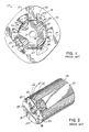
- FIG. 3 shows a switched reluctance motor rotor 50 in accordance with the invention.
- the rotor comprises a central annular hub 52 having a plurality of rotor poles 53, 54, 55, 56 extending radially outwardly therefrom.
- the rotor poles are circumferentially spaced and have gaps 57, 58, 59, 60 therebetween.
- Retention structure is provided on hub 52 in the gaps in the form of tangs 61, 62, 63, 64 extending radially outwardly from hub 52 into gaps 57, 58, 59, 60, respectively.
- Electrically insulating material 65, 66, 67, 68 such as bakelite, nylon, or valox, is provided in gaps 57, 58, 59, 60, respectively, and retained therein by tangs 61, 62, 63, 64, respectively.
- Each of tangs 61-64 has a radial length substantially less than the radial length of rotor poles 53-56 such that the outer tip such as 70 of the tang is spaced substantially radially inwardly of the arc of travel of the outer tip such as 72 of the rotor pole. This is desirable because it minimizes magnetic flux path lines through the tang, in contrast to fingers 34 and 36 of FIGS. 1 and 2.
- Tang 61 has distally opposite sides 74 and 76 with inner root ends 78 and 80 at hub 52 and outer ends 82 and 84 spaced radially outwardly of hub 52.
- the circumferential spacing between inner root ends 78 and 80 is less than the circumferential spacing between outer ends 82 and 84.
- Distally opposite sides 74 and 76 diverge away from each other as they extend away from hub 52. The remaining tangs are comparable.
- FIG. 4 shows a plurality of rotor laminations 86, 87, etc. stacked axially to form a laminated stack having axial ends 88 and 90.
- Electric insulation material 65-68 is part of a one-piece unitary harness 92 molded in-situ axially around the laminated stack and structurally enhancing the hold-together strength thereof.
- Harness 92 has a plurality of axial runners provided by the noted insulation material 65, 66, 67, 68 extending axially along gaps 57, 58, 59, 60, respectively, and integral with a pair of annular end rings 94 and 96 on axial ends 88 and 90.
- Axial runners 65-68 extend axially beyond the end rotor laminations 86 and 98 of the laminated stack and merge into annular end rings 94 and 96.
- Axial runners 65-68 have a given radial extension in respective gaps 57-60, and annular end rings 94 and 96 have a given radial extension at least partially overlapping the radial extension of axial runners 65-68.
- the outer radius 100 of axial runners 65-68 is the same as the outer radius 102 of annular end rings 94 and 96.
- the inner radius 104 of axial runners 65-68 is greater than the inner radius 106 of annular end rings 94 and 96.
- the inner radius 106 of annular end rings 94 and 96 is greater than the inner radius 108 of rotor 50.
- the electrically insulating molded material 65-68 integrally formed both in gaps 57-60 and on axial ends 88 and 90 provides in combination axial runners 65-68 of molded material extending axially along gaps 57-60 and integral with annular end rings 94 and 96 of molded material on axial ends 88 and 90, which combination further structurally enhances the hold-together strength of the laminated stack.
Landscapes
- Engineering & Computer Science (AREA)
- Power Engineering (AREA)
- Synchronous Machinery (AREA)
- Iron Core Of Rotating Electric Machines (AREA)
Applications Claiming Priority (2)
| Application Number | Priority Date | Filing Date | Title |
|---|---|---|---|
| US429823 | 1989-10-31 | ||
| US07/429,823 US5023502A (en) | 1989-10-31 | 1989-10-31 | Switched reluctance motor rotor |
Publications (3)
| Publication Number | Publication Date |
|---|---|
| EP0426376A2 true EP0426376A2 (de) | 1991-05-08 |
| EP0426376A3 EP0426376A3 (en) | 1991-06-26 |
| EP0426376B1 EP0426376B1 (de) | 1993-12-01 |
Family
ID=23704871
Family Applications (1)
| Application Number | Title | Priority Date | Filing Date |
|---|---|---|---|
| EP90311716A Expired - Lifetime EP0426376B1 (de) | 1989-10-31 | 1990-10-25 | Rotor für einen getakteten Reluktanzmotor |
Country Status (5)
| Country | Link |
|---|---|
| US (1) | US5023502A (de) |
| EP (1) | EP0426376B1 (de) |
| CA (1) | CA2027393C (de) |
| DE (1) | DE69004935T2 (de) |
| IE (1) | IE63957B1 (de) |
Cited By (6)
| Publication number | Priority date | Publication date | Assignee | Title |
|---|---|---|---|---|
| EP0625819A1 (de) * | 1993-05-19 | 1994-11-23 | Siemens Aktiengesellschaft | Reluktanzmotor, insbesondere zum Antrieb eines Waschautomaten |
| EP0668652A1 (de) * | 1994-02-16 | 1995-08-23 | Emerson Electric Co. | Vergossene Nase eines geschalteten Reluktanzrotors |
| EP1050947A1 (de) * | 1999-05-05 | 2000-11-08 | Lucas Industries Limited | Rotor für eine elektrische Maschine und eine elektrische Maschine mit solch einem Rotor |
| EP1879278A1 (de) * | 2006-07-13 | 2008-01-16 | Moteurs Leroy-Somer | Rotor einer elektrischen umlaufenden Maschine und Herstellungsverfahren |
| CN102856993A (zh) * | 2011-06-28 | 2013-01-02 | 三星电机株式会社 | 开关磁阻电机 |
| WO2013117480A3 (de) * | 2012-02-10 | 2014-07-31 | Ksb Aktiengesellschaft | Rotor und reluktanzmotor |
Families Citing this family (32)
| Publication number | Priority date | Publication date | Assignee | Title |
|---|---|---|---|---|
| SE465696B (sv) * | 1988-08-25 | 1991-10-14 | Vilmos Toeroek | Elektrisk motor och anordning foer matning av en saadan motor |
| SE467852B (sv) * | 1990-12-28 | 1992-09-21 | Vilmos Toeroek | Elektrisk motor |
| US5256923A (en) * | 1992-05-11 | 1993-10-26 | A. O. Smith Corporation | Switched reluctance motor with sensorless position detection |
| US5296773A (en) * | 1993-04-20 | 1994-03-22 | General Motors Corporation | Composite rotor for a synchronous reluctance machine |
| GB9507272D0 (en) * | 1995-04-07 | 1995-05-31 | Switched Reluctance Drives Ltd | Rotor for reluctance machines |
| GB9507391D0 (en) * | 1995-04-10 | 1995-05-31 | Switched Reluctance Drives Ltd | Method and apparatus for reducing winding failures in switched reluctance machines |
| EP0748027B1 (de) * | 1995-06-07 | 2006-09-06 | General Electric Company | Dynamoelektrische Maschine und deren Rotorkonstruktion |
| US5969454A (en) * | 1995-10-19 | 1999-10-19 | Tridelta Industries, Inc. | Switched reluctance motor |
| US6028385A (en) * | 1995-10-19 | 2000-02-22 | Tridelta Industries, Inc. | Switched reluctance motor |
| US6060809A (en) * | 1995-10-19 | 2000-05-09 | Tridelta Industries, Inc. | Staggered pole switched reluctance motor |
| US5852334A (en) * | 1995-10-19 | 1998-12-22 | Tridelta Industries, Inc. | Staggered pole switched reluctance motor |
| US6051903A (en) * | 1995-10-19 | 2000-04-18 | Tridelta Industries, Inc. | Switched reluctance motor |
| US5703421A (en) * | 1996-05-24 | 1997-12-30 | The United States Of America As Represented By The Secretary Of The Air Force | Reluctance generator/motor cooling |
| US5892306A (en) * | 1997-03-24 | 1999-04-06 | Emerson Electric Co. | Method and apparatus for balancing a load with a salient pole rotor machine |
| US5780945A (en) * | 1997-03-24 | 1998-07-14 | Emerson Electric Co. | Switched reluctance machine balancing system: material removal approach and material addition approach |
| WO2000064028A1 (en) * | 1999-04-20 | 2000-10-26 | Thermo Black Clawson Inc. | High efficiency submersible electric motor and components |
| US6707206B2 (en) * | 2002-01-23 | 2004-03-16 | Energy Saving Tech. Corp. | Magnetic material fixing structure of motor rotor |
| KR100465712B1 (ko) * | 2002-11-04 | 2005-01-13 | 엘지전자 주식회사 | 스위치드 릴럭턴스 모터 |
| US6911756B1 (en) * | 2004-03-23 | 2005-06-28 | Chio-Sung Chang | Rotor core with magnets on the outer periphery of the core having a sine or trapezoidal wave |
| US7157827B2 (en) * | 2004-09-21 | 2007-01-02 | A. O. Smith Corporation | Spoke permanent magnet rotor |
| US7230360B2 (en) * | 2004-11-08 | 2007-06-12 | Illinois Institute Of Technology | Switched reluctance machine |
| US7709991B2 (en) * | 2005-12-08 | 2010-05-04 | A. O. Smith Corporation | Rotor assembly for an electric machine including a vibration damping member and method of manufacturing same |
| US20070132335A1 (en) * | 2005-12-08 | 2007-06-14 | Ionel Dan M | Rotor assembly having a reduced back portion and a method of manufacturing same |
| US8035273B2 (en) * | 2005-12-08 | 2011-10-11 | A.O. Smith Corporation | Rotor assembly having two core portions each with a reduced back portion |
| GB2481853B (en) | 2010-07-09 | 2012-07-25 | Imra Europe Sas | Electric motor |
| CN202221930U (zh) * | 2011-08-11 | 2012-05-16 | 中山大洋电机制造有限公司 | 一种电机永磁转子结构 |
| US9882440B2 (en) | 2012-10-15 | 2018-01-30 | Regal Beloit America, Inc. | Radially embedded permanent magnet rotor and methods thereof |
| US9831727B2 (en) | 2012-10-15 | 2017-11-28 | Regal Beloit America, Inc. | Permanent magnet rotor and methods thereof |
| US9246364B2 (en) | 2012-10-15 | 2016-01-26 | Regal Beloit America, Inc. | Radially embedded permanent magnet rotor and methods thereof |
| US9099905B2 (en) | 2012-10-15 | 2015-08-04 | Regal Beloit America, Inc. | Radially embedded permanent magnet rotor and methods thereof |
| US9362792B2 (en) | 2012-10-15 | 2016-06-07 | Regal Beloit America, Inc. | Radially embedded permanent magnet rotor having magnet retention features and methods thereof |
| JP2021191065A (ja) * | 2020-05-28 | 2021-12-13 | 現代自動車株式会社Hyundai Motor Company | スイッチドリラクタンスモータ |
Family Cites Families (20)
| Publication number | Priority date | Publication date | Assignee | Title |
|---|---|---|---|---|
| DE304420C (de) * | ||||
| GB190508802A (en) * | 1905-04-26 | 1906-01-04 | John Scarisbrick Walker | Improvements in or in connection with Lubricating Valves. |
| FR1210349A (fr) * | 1958-09-20 | 1960-03-08 | Procédé de fabrication de rotor de machines électriques | |
| US3157806A (en) * | 1959-11-05 | 1964-11-17 | Bbc Brown Boveri & Cie | Synchronous machine with salient poles |
| US3611556A (en) * | 1968-01-20 | 1971-10-12 | Nippon Denso Co | Method of manufacturing a rotor for small rotary electric machines |
| US3588557A (en) * | 1969-02-19 | 1971-06-28 | Westinghouse Electric Corp | Low loss ventilation for salient pole machines |
| SU484604A1 (ru) * | 1972-12-14 | 1975-09-15 | Центральное Проектно-Конструкторское И Технологическое Бюро Крупных Электрических Машин | Ротор синхронной внополюсной электрической машины |
| DE2317500A1 (de) * | 1973-04-04 | 1974-10-10 | Siemens Ag | Elektrische synchronmaschine homopolarer bauart |
| US3882336A (en) * | 1973-12-03 | 1975-05-06 | Briggs & Stratton Corp | Electric motor armature core |
| DE2605815A1 (de) * | 1976-02-11 | 1977-08-18 | Siemens Ag | Elektrische schenkelpolmaschine mit einem luftgekuehlten schenkelpollaeufer |
| JPS5330702A (en) * | 1976-09-02 | 1978-03-23 | Toshiba Corp | Salient-pole field coil supporter and its production method |
| JPS5537883A (en) * | 1978-09-09 | 1980-03-17 | Hitachi Ltd | Salient-pole rotor |
| US4260921A (en) * | 1978-12-26 | 1981-04-07 | The Garrett Corporation | Permanent magnet rotor assembly having rectangularly shaped tongues |
| JPS5928852A (ja) * | 1982-08-06 | 1984-02-15 | Hitachi Ltd | 突極形回転電機 |
| US4525925A (en) * | 1983-09-22 | 1985-07-02 | General Electric Company | Method of making permanent magnet rotor |
| US4504755A (en) * | 1983-11-03 | 1985-03-12 | Kollmorgen Technologies Corporation | Rotor reluctance notch for cogging control |
| EP0156606B1 (de) * | 1984-03-17 | 1991-02-27 | Isuzu Motors Limited | Generatorvorrichtung |
| EP0180815B2 (de) * | 1984-10-19 | 1994-12-28 | Kollmorgen Corporation | Variable Reluktanzmaschine mit variabler Geschwindigkeit |
| US4674178A (en) * | 1985-10-16 | 1987-06-23 | Sundstrand Corporation | Method of fabricating a permanent magnet rotor |
| IT1208879B (it) * | 1987-04-30 | 1989-07-10 | Isoflux Servomotors Spa | Macchina elettrica a riluttanza |
-
1989
- 1989-10-31 US US07/429,823 patent/US5023502A/en not_active Expired - Fee Related
-
1990
- 1990-10-11 CA CA002027393A patent/CA2027393C/en not_active Expired - Fee Related
- 1990-10-23 IE IE381490A patent/IE63957B1/en not_active IP Right Cessation
- 1990-10-25 DE DE90311716T patent/DE69004935T2/de not_active Expired - Fee Related
- 1990-10-25 EP EP90311716A patent/EP0426376B1/de not_active Expired - Lifetime
Cited By (12)
| Publication number | Priority date | Publication date | Assignee | Title |
|---|---|---|---|---|
| EP0625819A1 (de) * | 1993-05-19 | 1994-11-23 | Siemens Aktiengesellschaft | Reluktanzmotor, insbesondere zum Antrieb eines Waschautomaten |
| WO1994027354A1 (de) * | 1993-05-19 | 1994-11-24 | Siemens Aktiengesellschaft | Reluktanzmotor, insbesondere zum antrieb eines waschautomaten |
| EP0668652A1 (de) * | 1994-02-16 | 1995-08-23 | Emerson Electric Co. | Vergossene Nase eines geschalteten Reluktanzrotors |
| EP1050947A1 (de) * | 1999-05-05 | 2000-11-08 | Lucas Industries Limited | Rotor für eine elektrische Maschine und eine elektrische Maschine mit solch einem Rotor |
| US6614142B1 (en) | 1999-05-05 | 2003-09-02 | Goodrich Control Systems Limited | Rotor for an electrical machine, and an electrical machine including such a rotor |
| EP1879278A1 (de) * | 2006-07-13 | 2008-01-16 | Moteurs Leroy-Somer | Rotor einer elektrischen umlaufenden Maschine und Herstellungsverfahren |
| FR2903824A1 (fr) * | 2006-07-13 | 2008-01-18 | Leroy Somer Moteurs | Rotor de machine tournante electrique et procede de fabrication |
| CN102856993A (zh) * | 2011-06-28 | 2013-01-02 | 三星电机株式会社 | 开关磁阻电机 |
| EP2541736A3 (de) * | 2011-06-28 | 2013-07-31 | Samsung Electro-Mechanics Co., Ltd | Geschalteter Reluktanzmotor |
| WO2013117480A3 (de) * | 2012-02-10 | 2014-07-31 | Ksb Aktiengesellschaft | Rotor und reluktanzmotor |
| RU2613664C2 (ru) * | 2012-02-10 | 2017-03-21 | КСБ Акциенгезельшафт | Ротор и реактивный индукторный двигатель |
| US9866077B2 (en) | 2012-02-10 | 2018-01-09 | Ksb Aktiengesellschaft | Rotor and reluctance motor |
Also Published As
| Publication number | Publication date |
|---|---|
| EP0426376A3 (en) | 1991-06-26 |
| IE903814A1 (en) | 1991-05-08 |
| US5023502A (en) | 1991-06-11 |
| IE63957B1 (en) | 1995-06-28 |
| DE69004935D1 (de) | 1994-01-13 |
| CA2027393A1 (en) | 1991-05-01 |
| DE69004935T2 (de) | 1994-03-24 |
| CA2027393C (en) | 1997-07-08 |
| EP0426376B1 (de) | 1993-12-01 |
Similar Documents
| Publication | Publication Date | Title |
|---|---|---|
| EP0426376B1 (de) | Rotor für einen getakteten Reluktanzmotor | |
| EP0872943B1 (de) | Elektrodynamische drehende Permanentmagnetmaschine mit konzentrierter Statorwicklung | |
| AU655517B2 (en) | Asynchronous induction motor | |
| US10432049B2 (en) | Rotor for a rotary electric machine | |
| US4556809A (en) | Combination synchronous and asynchronous electric motor | |
| EP0621677A2 (de) | Rotoraufbau | |
| EP0803962A1 (de) | Blechpaket für Dauermagnetrotoren für Generatoren oder dergleichen | |
| US6949855B2 (en) | Transverse flux electrical machine with toothed rotor | |
| EP0560007A1 (de) | Ständerzungen eines elektrischen Motors | |
| KR920015676A (ko) | 개량된 회전자 및 고정자를 갖는 고효율 저리액턴스의 원판형 기계 | |
| EP1005135B1 (de) | Elektrische Maschine und Rotor zur Verwendung darin | |
| US11569717B2 (en) | Axial flux rotary electric machine | |
| EP0478814A1 (de) | Motorstator mit Hitzedorn | |
| EP0429729A1 (de) | Elektrische Maschinen mit einem einen Eisenkern aufweisenden Scheibenanker | |
| US5001378A (en) | Rotor with reduced windage losses | |
| US20170040855A1 (en) | Rotor for a rotary electric machine | |
| US8604659B2 (en) | Stator with insulation for an electric motor, insulation for a stator, and electric power tool | |
| US3590301A (en) | Rotor for dynamoelectric machine | |
| EP0278200A1 (de) | Ankeranordnung und Motorkonstruktion und Verfahren zur Herstellung derselben | |
| US6885120B2 (en) | Structural enclosed rotor configuration for electric machine | |
| US2575932A (en) | Dynamoelectric machine rotor and winding | |
| US2427282A (en) | Wound armature for electric machines | |
| JPS60156234A (ja) | モ−タ | |
| EP0309076A2 (de) | Kommutierung bei elektrischen Motoren | |
| US20070024150A1 (en) | Electrical machine having centrally disposed stator |
Legal Events
| Date | Code | Title | Description |
|---|---|---|---|
| PUAI | Public reference made under article 153(3) epc to a published international application that has entered the european phase |
Free format text: ORIGINAL CODE: 0009012 |
|
| AK | Designated contracting states |
Kind code of ref document: A2 Designated state(s): DE FR IT |
|
| PUAL | Search report despatched |
Free format text: ORIGINAL CODE: 0009013 |
|
| AK | Designated contracting states |
Kind code of ref document: A3 Designated state(s): DE FR IT |
|
| 17P | Request for examination filed |
Effective date: 19910723 |
|
| 17Q | First examination report despatched |
Effective date: 19930301 |
|
| GRAA | (expected) grant |
Free format text: ORIGINAL CODE: 0009210 |
|
| AK | Designated contracting states |
Kind code of ref document: B1 Designated state(s): DE FR IT |
|
| ITF | It: translation for a ep patent filed | ||
| REF | Corresponds to: |
Ref document number: 69004935 Country of ref document: DE Date of ref document: 19940113 |
|
| ET | Fr: translation filed | ||
| PLBE | No opposition filed within time limit |
Free format text: ORIGINAL CODE: 0009261 |
|
| STAA | Information on the status of an ep patent application or granted ep patent |
Free format text: STATUS: NO OPPOSITION FILED WITHIN TIME LIMIT |
|
| 26N | No opposition filed | ||
| PGFP | Annual fee paid to national office [announced via postgrant information from national office to epo] |
Ref country code: FR Payment date: 20011012 Year of fee payment: 12 |
|
| PGFP | Annual fee paid to national office [announced via postgrant information from national office to epo] |
Ref country code: DE Payment date: 20011029 Year of fee payment: 12 |
|
| PG25 | Lapsed in a contracting state [announced via postgrant information from national office to epo] |
Ref country code: DE Free format text: LAPSE BECAUSE OF NON-PAYMENT OF DUE FEES Effective date: 20030501 |
|
| PG25 | Lapsed in a contracting state [announced via postgrant information from national office to epo] |
Ref country code: FR Free format text: LAPSE BECAUSE OF NON-PAYMENT OF DUE FEES Effective date: 20030630 |
|
| REG | Reference to a national code |
Ref country code: FR Ref legal event code: ST |
|
| PG25 | Lapsed in a contracting state [announced via postgrant information from national office to epo] |
Ref country code: IT Free format text: LAPSE BECAUSE OF NON-PAYMENT OF DUE FEES;WARNING: LAPSES OF ITALIAN PATENTS WITH EFFECTIVE DATE BEFORE 2007 MAY HAVE OCCURRED AT ANY TIME BEFORE 2007. THE CORRECT EFFECTIVE DATE MAY BE DIFFERENT FROM THE ONE RECORDED. Effective date: 20051025 |