EP0426431B1 - Spray heads - Google Patents
Spray heads Download PDFInfo
- Publication number
- EP0426431B1 EP0426431B1 EP90311872A EP90311872A EP0426431B1 EP 0426431 B1 EP0426431 B1 EP 0426431B1 EP 90311872 A EP90311872 A EP 90311872A EP 90311872 A EP90311872 A EP 90311872A EP 0426431 B1 EP0426431 B1 EP 0426431B1
- Authority
- EP
- European Patent Office
- Prior art keywords
- distributor
- spray
- tank
- flow passage
- hub
- Prior art date
- Legal status (The legal status is an assumption and is not a legal conclusion. Google has not performed a legal analysis and makes no representation as to the accuracy of the status listed.)
- Expired - Lifetime
Links
Images


Classifications
-
- B—PERFORMING OPERATIONS; TRANSPORTING
- B08—CLEANING
- B08B—CLEANING IN GENERAL; PREVENTION OF FOULING IN GENERAL
- B08B9/00—Cleaning hollow articles by methods or apparatus specially adapted thereto
- B08B9/08—Cleaning containers, e.g. tanks
- B08B9/093—Cleaning containers, e.g. tanks by the force of jets or sprays
- B08B9/0936—Cleaning containers, e.g. tanks by the force of jets or sprays using rotating jets
-
- B—PERFORMING OPERATIONS; TRANSPORTING
- B05—SPRAYING OR ATOMISING IN GENERAL; APPLYING FLUENT MATERIALS TO SURFACES, IN GENERAL
- B05B—SPRAYING APPARATUS; ATOMISING APPARATUS; NOZZLES
- B05B3/00—Spraying or sprinkling apparatus with moving outlet elements or moving deflecting elements
- B05B3/02—Spraying or sprinkling apparatus with moving outlet elements or moving deflecting elements with rotating elements
- B05B3/04—Spraying or sprinkling apparatus with moving outlet elements or moving deflecting elements with rotating elements driven by the liquid or other fluent material discharged, e.g. the liquid actuating a motor before passing to the outlet
- B05B3/0417—Spraying or sprinkling apparatus with moving outlet elements or moving deflecting elements with rotating elements driven by the liquid or other fluent material discharged, e.g. the liquid actuating a motor before passing to the outlet comprising a liquid driven rotor, e.g. a turbine
- B05B3/0425—Spraying or sprinkling apparatus with moving outlet elements or moving deflecting elements with rotating elements driven by the liquid or other fluent material discharged, e.g. the liquid actuating a motor before passing to the outlet comprising a liquid driven rotor, e.g. a turbine actuated downstream of the outlet elements
- B05B3/0426—Spraying or sprinkling apparatus with moving outlet elements or moving deflecting elements with rotating elements driven by the liquid or other fluent material discharged, e.g. the liquid actuating a motor before passing to the outlet comprising a liquid driven rotor, e.g. a turbine actuated downstream of the outlet elements the liquid driven rotor being a deflecting rotating element
Definitions
- the present invention relates to spray heads, to tank-flushing assemblies incorporating one or more such spray heads and to spray application equipment provided therewith e.g. for use in agriculture, horticulture and forestry.
- the spray tank In order to decontaminate agricultural spray application equipment after use, normally the spray tank must be filled to the neck with water to rinse chemical solution from all internal surfaces. The washing procedure may have to be repeated several times when changing to a different pesticide. As tractor mounted sprayers commonly have capacities of 1500 litres or more, the volume of contaminated washings generated can be substantial. Where the washings must be sprayed out, this is wasteful of both the land area required and the operators' time.
- GB-A-8828270 discloses a tank-flushing assembly in which only a fraction of the rinse water hitherto required is sprayed over the inner walls of the tank in a recirculating flow. Reducing the amount of liquid in this way effects a corresponding reduction in the required capacity or area of any disposal facility, and reduces the time needed to clean out the tank(s).
- GB-A-2188255 discloses a tank-flushing assembly in which a distributor disc is apertured to allow an axial flow of flushing liquid to reach both sides of the disc. In operation, the disc rotates to produce two fan-shaped sprays, one on one side and one on the other side of the rotation plane of the disc.
- obstructed tank i.e. they contain one or more internal obstructions such as internal hoses, filter baskets etc.
- Some designs of obstructed tank have features moulded into the tanks which cause channelling or separation of the down-wash from the tank walls.
- a channel is moulded around the waistline of the tank to locate a horizontal mounting strap and the resulting protrusion inside the tank interrupts the down-wash from the simple overhead spray heads so that there is a risk of pockets of chemical residue being left behind underneath the protrusion.
- British Patent Specification GB-A-1051305 discloses a tank flushing assembly in which a redistributor rotor is supported on outrigger arms which prevent an even spray distribution being established.
- the rotor is mounted on a ball race which can clog up or run rough in the hostile environment in which the assembly is to be used.
- An object of the present invention is to provide an improved spray head e.g. for use in tank-flushing assemblies of the kind disclosed in UKPA 88 28270 (GB-A-2 226 491).
- a spray head comprising a flow passage, a rotary distributor having a rotary distributor plate mounted with its axis of rotation co-axial with said flow passage and presenting an operative surface lying forwardly of the flow passage and obliquely to said axis, and helically disposed or functionally similar impeller surfaces provided on the distributor and operative to derive a distributor-rotating reaction force when contacted by a forward flow of liquid from the flow passage characterised in that the operative surface of the distributor plate is imperforate, the impeller surfaces are provided on said operative surface, and the distributor includes a hub portion mounted in and surrounded by a hollow support with the hub/support clearance space providing said flow passage, whereby in operation, the distributor plate rotates to redirect liquid forwardly and rearwardly without interruption.
- the clearance between the hub portion and the support is such that the ratio of the cross-sectional area of the clearance space relative to the cross-sectional area of the hub lies in the range 0.29 to 0.50.
- Specific embodiments of the present invention are intended for use in flushing the spray tanks of agricultural spray application equipment and liquid storage equipment e.g. bulk milk tanks.
- These spray heads may either be fitted as part of the original equipment or they may be supplied in kit form for retro-fitting to existing equipment.
- the invention also includes tank flushing assemblies incorporating one or more spray heads in accordance with the present invention and spray application equipment or liquid storage equipment provided with such assemblies.
- the illustrated spray head unit 10 comprises a distributor 12 which is rotationally mounted in an upper support 14. This latter acts as a bulkhead fitting to fix unit 10 in a suitable hole drilled into the tank top 16.
- the support is secured in plane by a location nut 18, rubber seals 20,21 being included to provide a water-tight fitting.
- the distributor 12 includes a hub portion 23, an obliquely inclined circular distributor plate 25 and impeller blades provided by four curved vanes 27 extending between the hub portion 23 and the distributor plate 25.
- a central boss 29 ( Figure 3) of the support 14 locates a steel pin 31 which acts as an axle for the rotating distributor 12.
- the axle pin 31 is preferably small in diameter e.g. 4 mm, to minimise friction.
- Reference numerals 33,34 indicate lock nuts at either end of pin 31.
- the support 14 is threaded to permit connection to a flush system pipework for the tank.
- liquid from this system can pass down through the three holes 36 provided around the boss 29 ( Figure 3) to flow through the passage provided by the annular hub/support clearance continuu 38 ( Figure 1). This has the effect of accelerating the liquid flow as it passes through the upper support on its way to the distributor plate 25, and of spreading the flow evenly around the distributor hub 23.
- the value chosen for the annular clearance space between the hub and its support should be such that the space:hub cross-sectional area ratio lies in the range 0.29 to 0.50. With smaller clearances, the resulting end thrust on the distributor 12 will inhibit its rotation while with larger clearances the flow velocity will be reduced below what is required to give an acceptable throw of spray from the rotating distributor 12.
- the four curved vanes 27 also act like turbine blades to induce rotation of the distributor about its vertical rotation axis.
- a nylon washer 43 is included between the bottom end of the distributor hub 23 and the lower retaining nut 34 on the pin 31.
- a similar washer 44 is provided at the top end of the boss 29.
- the nut 34 and washer 44 are replaced by a thick PTFE thrust washer attached to the axle 31 by a split pin passing through both components.
- some sort of spring clip may be used instead to secure the PTFE washer in place.
- the distributor plate 25 can be inclined at any suitable angle to the rotation axis of the distributor, the value chosen in any particular case being necessarily a compromise between flow pattern depth and side thrust on the axle pin 31, both of which increase as the plate angle to the distributor's rotation axis decreases.
- the angle of 60° chosen for the illustrated embodiment is a typical value where two such spray heads are to be used in the manner of Figure 4 for the usual sort of spray tanks currently in use on commercially available agricultural spray application equipment.
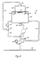
- spray application equipment 50 comprises a spray boom 52, a tank 54 for the liquid (herbicide etc.) to be applied by the boom, and a pump 56 for moving liquid from the tank to the spray boom through a suction filter 58, main control valve 60 and delivery filter 62.
- Reference numeral 64 indicates the usual pressure guage while reference numeral 66 indicates a conventional by-pass agitator feed with its pressure relief valve 68.
- the tank 54 is top-loaded through the usual inlet port filter 70.
- the tank 54 may be partially filled with water for rinsing purposes and in accordance with another aspect of the present invention, a rinse recirculation line 72 is tapped off from the usual "spray-off" return line 74 and a suitable two way valve is provided at 76. With valve 76 open, the return line 72 will operate in the usual way, but when valve 76 is closed, liquid which would have returned through the valve direct to the tank 54, is instead redirected via tapping 78 into the rinse recirculation line 72.
- the recirculation line is connected via a T-junction 80 and two equal-length hoses 82,83 to two spray heads 10 each as hereinbefore described and illustrated with reference to the earlier Figures.
- the tank 54 is filled about one tenth full with water. Then, with valve 76 closed and the main control valve 60 turned to its alternative position (rather than to that illustrated in Figure 4), the pump 56 is used to circulate rinsing water from the tank 54 along line 72 and back through the spray heads 10 as above described. This process is continued until the walls of the tank have been thoroughly rinsed by the spray from spray heads 10 whereupon the one way valve 76 is again opened and control valve 60 is returned to its illustrated position to spray out the contaminated washings through the nozzles on spray boom 52.
- the illustrated spray head is intended to be applicable to any spray tank, and may be either fitted as original equipment, or supplied in kit form for retro-fitting to existing equipment without major modification (for example without fitting an extra tank).
- valve 76 is omitted and the tapping 78 is replaced by a three-way valve 90 providing an L-shaped flow channel 92 in its spherical valve member 94.
- control knob 96 is set as shown in Figure 5(b) and the valve connects the "spray-off" return line 74 directly to the tank 54 to promote agitation of the spray liquid remaining in the tank. In this position, the rinse re-circulation line 72 is shut off by the valve to prevent dribble from the spray heads 10.
- valve member When spraying has been completed and it is desired to rinse the tank, the valve member is rotated to the position shown in Figure 5(d) so that the rinse water now in tank 54 can be directed via return line 74 and re-circulation line 72 to the spray heads 10.
- Pilot holes 98,99 formed in the side walls of the flow channel 92 prevent the flow from line 74 from being interrupted as the valve passes through tie midway position shown in Figure 5(c). This avoids the pressure pulse that would otherwise result as the valve member 94 is rotated from one position to the other and the consequent blow-off of the push-fit hoses used for lines 74 etc.
- the principal advantage of the present invention e.g. over the system of UKPA 8828270, is that a more efficient flushing of the more complexly shaped spray tanks can be obtained than hitherto. This is firstly because rotating the direction of the rinsing spray reduces the chance of missed areas, either behind obstructions or where the flow is channel led, and secondly, because part of the spray can be directed to the lower regions in the tank which may be masked from a simple symmetrical overhead spray.
- the present invention also shares with the system of UKPA 8828270 the advantage over the prior art systems that significantly less time is required than with the conventional fill-and-discharge rinsing technique previously employed.
- the assembly may include only a single such spray head or it may include three or more such spray heads, if desired.
- the pump or pumps used should preferably be able to supply the or each such spray head with at least 40 litres per minute of the flushing liquid.
Landscapes
- Engineering & Computer Science (AREA)
- Mechanical Engineering (AREA)
- Catching Or Destruction (AREA)
- Details Or Accessories Of Spraying Plant Or Apparatus (AREA)
Applications Claiming Priority (2)
| Application Number | Priority Date | Filing Date | Title |
|---|---|---|---|
| GB898924475A GB8924475D0 (en) | 1989-10-31 | 1989-10-31 | Spray heads |
| GB8924475 | 1989-10-31 |
Publications (2)
| Publication Number | Publication Date |
|---|---|
| EP0426431A1 EP0426431A1 (en) | 1991-05-08 |
| EP0426431B1 true EP0426431B1 (en) | 1994-04-20 |
Family
ID=10665454
Family Applications (1)
| Application Number | Title | Priority Date | Filing Date |
|---|---|---|---|
| EP90311872A Expired - Lifetime EP0426431B1 (en) | 1989-10-31 | 1990-10-30 | Spray heads |
Country Status (7)
| Country | Link |
|---|---|
| US (1) | US5139199A (da) |
| EP (1) | EP0426431B1 (da) |
| AU (1) | AU6564690A (da) |
| CA (1) | CA2029092A1 (da) |
| DE (1) | DE69008308T2 (da) |
| DK (1) | DK0426431T3 (da) |
| GB (2) | GB8924475D0 (da) |
Cited By (2)
| Publication number | Priority date | Publication date | Assignee | Title |
|---|---|---|---|---|
| DE102016102727A1 (de) | 2015-08-17 | 2017-02-23 | Netzsch-Feinmahltechnik Gmbh | Reinigungsvorrichtung und produktverarbeitende Anlage |
| CN109719096A (zh) * | 2018-12-06 | 2019-05-07 | 文林涛 | 一种化妆品玻璃瓶的环形自动清洗系统的玻璃瓶固定机构 |
Families Citing this family (4)
| Publication number | Priority date | Publication date | Assignee | Title |
|---|---|---|---|---|
| US5530223A (en) * | 1993-08-05 | 1996-06-25 | Angelo Po Grandi Cucine S.P.A. | Convection and steam oven with a pre-atomizer |
| GB0716310D0 (en) * | 2007-08-21 | 2007-10-03 | Simply Clean Ltd | Rotary tool |
| US8376060B2 (en) * | 2007-11-30 | 2013-02-19 | The Viking Corporation | Adjustable escutcheon assembly for a sprinkler |
| US8844642B2 (en) * | 2008-09-05 | 2014-09-30 | Elkhart Brass Manufacturing Company, Inc. | Automatic flow restrictor for firefighting apparatus |
Family Cites Families (16)
| Publication number | Priority date | Publication date | Assignee | Title |
|---|---|---|---|---|
| US1322466A (en) * | 1919-11-18 | elorida | ||
| GB1051305A (da) * | 1900-01-01 | |||
| US1078543A (en) * | 1911-06-13 | 1913-11-11 | Frederick H Johnson | Lawn-sprinkling device. |
| AT170163B (de) * | 1948-08-27 | 1952-01-25 | Karl Georg Wanke | Regner zur Beregnung von Flächen geringen Ausmaßes |
| US3081949A (en) * | 1962-02-13 | 1963-03-19 | Odys R Simmons | Water dispersal apparatus |
| DE1500624A1 (de) * | 1965-07-05 | 1969-06-19 | Vegeby Anders Uno Ingvar | Verteilerdruese fuer Fluessigkeiten |
| GB1196746A (en) * | 1967-05-30 | 1970-07-01 | Terence Derwent Siddall | Improvements relating to Liquid Sprayers Particularly for Washing Apparatus. |
| GB1343337A (en) * | 1971-06-24 | 1974-01-10 | Diversey Dev Ltd | Liquid spray devices |
| GB1442662A (en) * | 1973-10-16 | 1976-07-14 | Diversey Ltd | Liquid spray devices |
| GB1486427A (en) * | 1974-03-27 | 1977-09-21 | Ciba Geigy Ag | Rotary atomiser |
| JPS6034421B2 (ja) * | 1978-07-03 | 1985-08-08 | 三菱プレシジヨン株式会社 | 外周に溝を有する空洞型流体反射分散器 |
| IL65199A0 (en) * | 1982-03-08 | 1982-05-31 | Rubinstein Zvi | Spray nozzle |
| US4685592A (en) * | 1985-11-29 | 1987-08-11 | Vanderjagt John A | Pumping system with control valve |
| IL77834A (en) * | 1986-02-10 | 1991-05-12 | Plastro Gvat | Rotary water sprinkler |
| GB2188255B (en) * | 1986-03-12 | 1990-03-28 | Breconcherry Steel | Tankwasher |
| GB2206043A (en) * | 1987-06-24 | 1988-12-29 | Spraysafe Automatic Sprinklers | Fire protection sprinklers |
-
1989
- 1989-10-31 GB GB898924475A patent/GB8924475D0/en active Pending
-
1990
- 1990-10-30 DK DK90311872.7T patent/DK0426431T3/da active
- 1990-10-30 DE DE69008308T patent/DE69008308T2/de not_active Expired - Fee Related
- 1990-10-30 GB GB9023579A patent/GB2237520B/en not_active Expired - Fee Related
- 1990-10-30 EP EP90311872A patent/EP0426431B1/en not_active Expired - Lifetime
- 1990-10-30 US US07/605,099 patent/US5139199A/en not_active Expired - Fee Related
- 1990-10-31 AU AU65646/90A patent/AU6564690A/en not_active Abandoned
- 1990-10-31 CA CA002029092A patent/CA2029092A1/en not_active Abandoned
Cited By (4)
| Publication number | Priority date | Publication date | Assignee | Title |
|---|---|---|---|---|
| DE102016102727A1 (de) | 2015-08-17 | 2017-02-23 | Netzsch-Feinmahltechnik Gmbh | Reinigungsvorrichtung und produktverarbeitende Anlage |
| WO2017028831A1 (de) | 2015-08-17 | 2017-02-23 | Netzsch-Feinmahltechnik Gmbh | Reinigungsvorrichtung und produktverarbeitende anlage |
| US11141745B2 (en) | 2015-08-17 | 2021-10-12 | Netzsch-Feinmahltechnik Gmbh | Cleaning device and product processing system |
| CN109719096A (zh) * | 2018-12-06 | 2019-05-07 | 文林涛 | 一种化妆品玻璃瓶的环形自动清洗系统的玻璃瓶固定机构 |
Also Published As
| Publication number | Publication date |
|---|---|
| DE69008308T2 (de) | 1994-08-04 |
| DK0426431T3 (da) | 1994-05-30 |
| GB8924475D0 (en) | 1989-12-20 |
| US5139199A (en) | 1992-08-18 |
| DE69008308D1 (de) | 1994-05-26 |
| EP0426431A1 (en) | 1991-05-08 |
| GB2237520A (en) | 1991-05-08 |
| GB9023579D0 (en) | 1990-12-12 |
| AU6564690A (en) | 1991-05-09 |
| GB2237520B (en) | 1993-07-21 |
| CA2029092A1 (en) | 1991-05-01 |
Similar Documents
| Publication | Publication Date | Title |
|---|---|---|
| US4394966A (en) | Spraying apparatus having a fluid storage tank with agitator and anti-vortex tank fittings | |
| US3288156A (en) | Dishwasher with upwardly extensible distributor | |
| EP0426431B1 (en) | Spray heads | |
| US5312047A (en) | Lawn mower washer ring | |
| EP0265107B1 (en) | Bidirectional pump with diaphragm operated valve for dishwasher | |
| DE202007019198U1 (de) | Wasserführendes Haushaltsgerät mit einer Wasserweiche | |
| WO1997036697A1 (en) | Computer controlled apparatus and method for the cleaning of tanks | |
| US5313682A (en) | Hand held domestic utensil cleaning device | |
| WO2019125665A1 (en) | Spray nozzle and method | |
| US4132358A (en) | Sprinkler nozzle | |
| US5232157A (en) | Insect resistant spray emitter | |
| CN208853041U (zh) | 一种园林绿化洒水喷头 | |
| US6152388A (en) | Spray nozzle apparatus | |
| EP1183983B1 (de) | Sprühvorrichtung für eine Geschirrspülmaschine | |
| CN209144465U (zh) | 喷嘴、波轮洗衣机及其喷淋系统和外桶盖 | |
| CN112218725A (zh) | 离心甩盘、离心式喷头、喷洒系统及可移动平台 | |
| EP2294962A1 (en) | Wash arm arrangement for a dishwasher | |
| US3340888A (en) | Chemical feeder | |
| DE102018206443A1 (de) | Haushalts-Geschirrspülmaschine | |
| CN219679239U (zh) | 一种可多角度且均匀混合的喷洒罐 | |
| US20030159722A1 (en) | Apparatus for cleaning a lawnmower | |
| CN207948134U (zh) | 一种水肥一体化灌溉系统 | |
| SE514366C2 (sv) | Anordning för homogenisering av en vätska | |
| JPH0315193Y2 (da) | ||
| JPH08131901A (ja) | 散水器 |
Legal Events
| Date | Code | Title | Description |
|---|---|---|---|
| PUAI | Public reference made under article 153(3) epc to a published international application that has entered the european phase |
Free format text: ORIGINAL CODE: 0009012 |
|
| AK | Designated contracting states |
Kind code of ref document: A1 Designated state(s): DE DK FR GB IT SE |
|
| 17P | Request for examination filed |
Effective date: 19910517 |
|
| RAP1 | Party data changed (applicant data changed or rights of an application transferred) |
Owner name: BRITISH TECHNOLOGY GROUP LTD |
|
| 17Q | First examination report despatched |
Effective date: 19921001 |
|
| GRAA | (expected) grant |
Free format text: ORIGINAL CODE: 0009210 |
|
| AK | Designated contracting states |
Kind code of ref document: B1 Designated state(s): DE DK FR GB IT SE |
|
| ITF | It: translation for a ep patent filed | ||
| REF | Corresponds to: |
Ref document number: 69008308 Country of ref document: DE Date of ref document: 19940526 |
|
| ET | Fr: translation filed | ||
| REG | Reference to a national code |
Ref country code: DK Ref legal event code: T3 |
|
| EAL | Se: european patent in force in sweden |
Ref document number: 90311872.7 |
|
| PLBE | No opposition filed within time limit |
Free format text: ORIGINAL CODE: 0009261 |
|
| STAA | Information on the status of an ep patent application or granted ep patent |
Free format text: STATUS: NO OPPOSITION FILED WITHIN TIME LIMIT |
|
| 26N | No opposition filed | ||
| PGFP | Annual fee paid to national office [announced via postgrant information from national office to epo] |
Ref country code: FR Payment date: 19980917 Year of fee payment: 9 |
|
| PGFP | Annual fee paid to national office [announced via postgrant information from national office to epo] |
Ref country code: DK Payment date: 19980918 Year of fee payment: 9 |
|
| PGFP | Annual fee paid to national office [announced via postgrant information from national office to epo] |
Ref country code: SE Payment date: 19980921 Year of fee payment: 9 Ref country code: DE Payment date: 19980921 Year of fee payment: 9 |
|
| PGFP | Annual fee paid to national office [announced via postgrant information from national office to epo] |
Ref country code: GB Payment date: 19981001 Year of fee payment: 9 |
|
| PG25 | Lapsed in a contracting state [announced via postgrant information from national office to epo] |
Ref country code: SE Free format text: THE PATENT HAS BEEN ANNULLED BY A DECISION OF A NATIONAL AUTHORITY Effective date: 19991030 Ref country code: GB Free format text: LAPSE BECAUSE OF NON-PAYMENT OF DUE FEES Effective date: 19991030 Ref country code: DK Free format text: LAPSE BECAUSE OF NON-PAYMENT OF DUE FEES Effective date: 19991030 |
|
| EUG | Se: european patent has lapsed |
Ref document number: 90311872.7 |
|
| GBPC | Gb: european patent ceased through non-payment of renewal fee |
Effective date: 19991030 |
|
| PG25 | Lapsed in a contracting state [announced via postgrant information from national office to epo] |
Ref country code: FR Free format text: LAPSE BECAUSE OF NON-PAYMENT OF DUE FEES Effective date: 20000630 |
|
| REG | Reference to a national code |
Ref country code: DK Ref legal event code: EBP |
|
| PG25 | Lapsed in a contracting state [announced via postgrant information from national office to epo] |
Ref country code: DE Free format text: LAPSE BECAUSE OF NON-PAYMENT OF DUE FEES Effective date: 20000801 |
|
| REG | Reference to a national code |
Ref country code: FR Ref legal event code: ST |
|
| PG25 | Lapsed in a contracting state [announced via postgrant information from national office to epo] |
Ref country code: IT Free format text: LAPSE BECAUSE OF NON-PAYMENT OF DUE FEES;WARNING: LAPSES OF ITALIAN PATENTS WITH EFFECTIVE DATE BEFORE 2007 MAY HAVE OCCURRED AT ANY TIME BEFORE 2007. THE CORRECT EFFECTIVE DATE MAY BE DIFFERENT FROM THE ONE RECORDED. Effective date: 20051030 |