EP0426582A2 - Umlegbare Parkplatzsperre - Google Patents
Umlegbare Parkplatzsperre Download PDFInfo
- Publication number
- EP0426582A2 EP0426582A2 EP90420467A EP90420467A EP0426582A2 EP 0426582 A2 EP0426582 A2 EP 0426582A2 EP 90420467 A EP90420467 A EP 90420467A EP 90420467 A EP90420467 A EP 90420467A EP 0426582 A2 EP0426582 A2 EP 0426582A2
- Authority
- EP
- European Patent Office
- Prior art keywords
- forestay
- main upright
- parking
- housing
- parking bollard
- Prior art date
- Legal status (The legal status is an assumption and is not a legal conclusion. Google has not performed a legal analysis and makes no representation as to the accuracy of the status listed.)
- Withdrawn
Links
- 230000004888 barrier function Effects 0.000 title claims description 22
- 230000000903 blocking effect Effects 0.000 claims description 4
- 238000006073 displacement reaction Methods 0.000 claims description 2
- 125000006850 spacer group Chemical group 0.000 description 7
- 239000002184 metal Substances 0.000 description 3
- 229910052751 metal Inorganic materials 0.000 description 3
- 230000035515 penetration Effects 0.000 description 2
- 239000004033 plastic Substances 0.000 description 2
- 239000003795 chemical substances by application Substances 0.000 description 1
- 238000011109 contamination Methods 0.000 description 1
- 238000002788 crimping Methods 0.000 description 1
- 239000000428 dust Substances 0.000 description 1
- 239000000463 material Substances 0.000 description 1
- 150000002739 metals Chemical class 0.000 description 1
- 230000004048 modification Effects 0.000 description 1
- 238000012986 modification Methods 0.000 description 1
- 239000002245 particle Substances 0.000 description 1
- 238000005476 soldering Methods 0.000 description 1
- 239000007787 solid Substances 0.000 description 1
- 229920002994 synthetic fiber Polymers 0.000 description 1
- XLYOFNOQVPJJNP-UHFFFAOYSA-N water Substances O XLYOFNOQVPJJNP-UHFFFAOYSA-N 0.000 description 1
- 238000003466 welding Methods 0.000 description 1
- 239000002023 wood Substances 0.000 description 1
Images



Classifications
-
- E—FIXED CONSTRUCTIONS
- E01—CONSTRUCTION OF ROADS, RAILWAYS, OR BRIDGES
- E01F—ADDITIONAL WORK, SUCH AS EQUIPPING ROADS OR THE CONSTRUCTION OF PLATFORMS, HELICOPTER LANDING STAGES, SIGNS, SNOW FENCES, OR THE LIKE
- E01F13/00—Arrangements for obstructing or restricting traffic, e.g. gates, barricades ; Preventing passage of vehicles of selected category or dimensions
- E01F13/04—Arrangements for obstructing or restricting traffic, e.g. gates, barricades ; Preventing passage of vehicles of selected category or dimensions movable to allow or prevent passage
- E01F13/08—Arrangements for obstructing or restricting traffic, e.g. gates, barricades ; Preventing passage of vehicles of selected category or dimensions movable to allow or prevent passage by swinging into closed position about a transverse axis situated in the road surface, e.g. tiltable sections of the road surface, tiltable parking posts
- E01F13/085—Arrangements for obstructing or restricting traffic, e.g. gates, barricades ; Preventing passage of vehicles of selected category or dimensions movable to allow or prevent passage by swinging into closed position about a transverse axis situated in the road surface, e.g. tiltable sections of the road surface, tiltable parking posts specially adapted for individual parking spaces
Definitions
- the device which is the subject of the invention is a folding parking terminal usable in particular as a parking barrier.
- Such devices which have the object of reserving the use of parking spaces for automobiles or other vehicles to specific users.
- This device comprises a base plate, having a U-shaped section with wings of low height, anchored to the ground.
- a straight upright also having a U-shaped section, is articulated at one end of the base plate so that it can stand vertically.
- a support piece forming inclined stay, is articulated by one of its ends to the free end of the base plate. The other end of the support piece slides, thanks to a transverse pin, in grooves formed in the wings of the right upright.
- the dimensions of these parts are such that the right upright can be folded down to the ground in the extension of the base plate, the support part coming to partially cover it.
- the end of the support piece which slides in the grooves of this straight upright joins the upper end of these grooves and can be locked in this position by suitable means such as 'a padlock.
- the right upright has at its free end a signal plate whose width is determined to prevent, when raised, the entry of vehicles into the parking space.
- the patent FR 2120398 describes another type of parking barrier, produced by means of tubular elements. It has a horizontal crosspiece, the ends of which are curved into a hoop and are articulated on the ground in separate bases.
- An oblique forestay comprises two telescopic tubular sections having, preferably, a rectangular section. The upper section is articulated on the crosspiece by means of a sleeve. The lower section is articulated on the ground in a base separate from the others.
- the lower section of the oblique forestay of smaller section, slides inside the other and comes into abutment against the articulated sleeve on the crosspiece.
- the barrier is locked in this position by a removable cylinder lock. This barrel which is engaged transversely in holes made in the two sections, plays the role of a removable locking pin. Note that in the folded position on the ground, the oblique telescopic forestay is in maximum extension.
- Patent FR 2118335 describes a retractable parking barrier which comprises a folding upright, of rectangular section, connected to a base by an articulation situated at its base and a spacer whose upper end forms a guide head by sliding in the upright, l the lower end being connected to the base.
- This amount has an opening which allows the passage of the rod of the spacer which is a simple metal rod of circular section; the length of this opening is sufficient to receive the spacer over its entire length when the upright is lowered to the ground.
- the width of the opening also allows to receive the lower articulation of the spacer.
- the parking barrier described in this document has the advantage of comprising a spacer relatively well protected by the upright in the folded position.
- this spacer does not really contribute to the transverse stability of the upright in the vertical position, given the large lateral clearance of the rod relative to the rectangular opening.
- the guide head has a variable play depending on the inclination of the upright; finally, the use according to FIG. 4 of an axis of articulation of the spacer guided by elongated holes drilled in the flanges of the upright is a cause of contamination of the slides by penetration of polluting agents coming from outside.
- the means for locking the vertical position of the upright require the use of a key often not very easy to implement.
- the folding parking terminal which is the subject of the invention does not have the drawbacks of the parking barriers which have just been described and makes it possible to achieve the aims which have been proposed.
- This parking bollard comprises a rectilinear main upright, articulated at one of its two ends around an axis on a base, so that it can be folded over the latter horizontally or straightened vertically.
- a forestay of fixed length is articulated at one of its two ends on the same base, around an axis parallel to that of the main upright and is connected to the main upright by a sliding connection means.
- the main upright comprises a housing having sufficient dimensions to allow the connection between the end of the forestay and this main upright to be carried out inside this housing and also allow the entire stay to come to be embedded there, when this main amount is folded on the base.
- the folding parking bollard comprises a forestay which cooperates with the main upright to give the assembly excellent mechanical strength, not only with respect to stresses in a plane perpendicular to the folding axis, but also vis-à-vis stresses having transverse components with respect to this plane.
- This stay consists of a sheet bent at right angles along at least two edges to form at least three sides of a quadrilateral.
- a locking means makes it possible to block the main upright, in a substantially vertical position, preventing any movement of the end of the forestay engaged in the housing along the slides, for a determined relative position of this forestay relative to the slides.
- This locking means is preferably automatic.
- the main upright preferably comprises barrier elements which are fixed on its lateral edges and extend transversely, overhanging.
- the particular structure of the assembly formed by the main upright and the forestay contributes in a particularly effective way to the stability of the bollard thus equipped with transverse elements forming a barrier.
- the main upright consists of a folded sheet in an open rectangle, the width of the opening allowing, as stated above, the forestay to be embedded in it with little play.
- the lateral zones of the main upright form slides on which guide means move, disposed on each side of the forestay near its end.
- These guide means are advantageously rollers mounted free in rotation on bearings integral with the walls of the forestay or shoes mounted on the forestay which slide along the slides.
- the locking means which makes it possible to block the sliding of the forestay in the housing of the main upright consists of a retaining hook which engages on a hooking piece of suitable section.
- One of the two components of this locking means is integral with the main upright and the other with the forestay.
- the retaining hook is mounted for rotation about an axis parallel to the hinge axes of the forestay and the main upright and is integral with this main upright.
- the attachment piece such as a rod capable of engaging in the catching area of the hook is then secured to the forestay.
- This attachment piece can be an extension of the rod which carries the guide means.
- the shape of the retaining hook is such that, when the main upright is raised vertically, the attachment piece comes into contact with its outer wall which is inclined so that this contact causes the rotation of the hook in the direction of opening, an elastic return means then allowing the closure of the hook which engages on the attachment piece. This ensures automatic locking with blocking of the forestay sliding.
- Two retaining hooks can each be used, each engaging a hooking piece which can be on each side of the forestay in the extension of the rod which carries the guide means.
- an unlocking means is constituted by a lock which controls the opening of the hook to allow the parking bollard to be lowered to the ground. This lock is preferably controlled by a key.
- an elastic balancing means is disposed between the main upright and forestay to facilitate lifting of the parking bollard from the folded down position.
- This elastic means is advantageously a helical spring stretched between a point of attachment of the main upright close to its axis of articulation on the base and a point of attachment of the forestay near its upper end.
- the attachment point of the main upright can be the articulation axis thereof and the attachment point of the forestay the transverse rod which carries the guide means.
- This box is in two parts articulated with respect to each other thanks to a hinge allowing an opening to 180 °. It has a housing which allows the parking bollard to be received and wedged in the housing in the folded position on its base. The two ends of the housing, remote from the hinge, have half-handles which fold over one another when closed so that they can be grasped with one hand.
- This housing has passages which allow the barrier elements to be positioned outside of this housing.
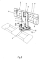
- FIG. 1 shows, in perspective, without details, a parking terminal 1 according to the invention.
- This parking bollard comprises a main post 2 articulated at one of its ends around an axis X1-X1 on a base 3.
- This base 3 is here constituted by a triangular plate anchored to the ground at three points by known means .
- a forestay 4 articulated by one of its ends on the base around an axis X2-X2 parallel to the axis X1-X1, and separated from the latter by a distance d1 comes to bear slidingly at its other end against the main amount 2 by committing to LG housing.
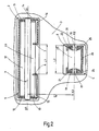
- FIG 2 the articulated connection mode of the forestay 4 and the main upright 2 with the base 3 whose periphery is not shown.
- the sections in the plane containing the axes X1-X1 and X2-X2 of the forestay 4 and the main upright 2 presented in this figure 2 each correspond to a vertical position wedge of this forestay 4 and of this upright 2, vertical positions which they cannot have simultaneously.
- the section of the main upright 2 is constituted by a sheet 5 folded into an open rectangle.
- the width of the opening L1 available between the folded edges 6 and 7 of the sheet 5 is greater than the overall width L2 of the forestay 4 in order to be able to receive the latter in the housing thus formed.
- the section of this stay is also constituted by a sheet 8 folded into an open rectangle whose opening is opposite that of the main upright 2.
- the articulation relative to the base 3 of this main upright 2 is achieved by means of 'a round rod 9, engaged in the holes forming bearing surfaces of fixing brackets 10, 11 connected by a support plate 12 itself secured to the base 3.
- the two ends of the rod 9 are themselves secured to the small sides 13, 14 of the main upright 2.
- the forestay 4 is articulated in a similar fashion to that of the main amount 2.
- Round rods 17, 18 secured to the short sides 19, 20 are engaged in the forma holes nt bearing of fixing yokes 21, 22 connected by a support plate 23 to the base 3.
- barrier elements which comprise metallic tubular sections 27, 28, 29, 30. These tubular sections are welded, brazed or crimped with the short sides 13, 14 of the main upright 2 and support end pieces 31, 32, for example of plastic.
- the end of the forestay 4 which cooperates with the main upright 2 by sliding along it comprises guide means.
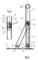
- These rollers 40, 41 are arranged so as to be able to slide on slides 43, 44, 45, 46 formed on the interior walls in the lateral zones of the main upright 2, on each side of the LG housing in which the forestay 4 is engaged.
- FIG. 4 shows, in section, in a plane of symmetry perpendicular to the articulation axes such as X1-X1, the parking bollard 1 folded down on the base 3 in the direction of the arrow F1 in FIG. 3. It can be seen that the end of the forestay 4, initially engaged in the LG housing of the main upright 2, slid thanks to its rollers 40, 41 to the vicinity of the upper end of the LG housing.
- the embodiment according to the invention of the strut 4 and the main upright 2 allows them to cooperate in a particularly effective manner to ensure excellent mechanical strength of the device under the conditions of use.
- This mechanical strength is particularly important when the parking bollard has cantilever elements forming a barrier such as 27, 28, 29, 30, 31, and 32.
- a helical balancing spring 50 is stretched between the upper end of the forestay 4 and the lower end of the main upright 2.
- the openings facing the forestay 4 and the main upright 2 allow the implementation of such a spring 50. It has, horizontally, as shown in Figure 4, its maximum extension.
- this spring is provided with a mooring hook at each of its two ends.
- the first hook 51 is engaged around the round rod 9 whose axis X1-X1 is fixed relative to the base.
- the second hook 52 is engaged around the rod 42 of axis X3-X3 secured to the short sides 19, 20 of the forestay 4 in the vicinity of the upper end thereof.
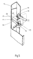
- Figures 5 to 7 show an embodiment of a locking and locking means of the parking terminal 1 in the closed position, that is to say that for which the main upright is vertical as is shown in Figure 3.
- a retaining hook 55 mounted in rotation around a bearing axis X4-X4, parallel to X3-X3, secured to a fitting 56 itself fixed inside the main upright 2 in the vicinity on the short side 13.
- the dimensions of the hook 55 and its location are determined so that, when the main upright 2 reaches substantially vertical, the axis X3-X3 of the transverse rod 42 which supports the rollers 40, 41 crosses the area hook catch 55.
- this rod 42 has an extension, having a suitable cross-section area forming hooking part 57, capable of engaging in this hook catch area 55 and thus achieving automatic locking.
- the upper face 58 of the hook 55 is inclined relative to the horizontal in a plane parallel to X4-X4, as shown in FIGS. 5 and 6, so that, when the zone of reduced section 57 of the rod 42 comes into contact with this upper face 58 the result of the force exerted causes the hook 55 to rotate in the direction of opening.
- the displacement along the main upright 2 of the rod 42 is stopped by the stop 59 secured to the fitting 56 when the main upright 2 reaches substantially vertical and the hook 55 closes on the reduced cross-section area 57 of the rod 42 under the action of the return spring 60 (see FIG. 6).
- This locking position is clearly shown at the retaining hook 55, in elevation in FIG. 6 and in plan in FIG. 7. In FIG.
- an unlocking means constituted by a lock 61, of axis substantially parallel to X4 - X4, which controls the opening of the hook 55 to allow the terminal 1 to be folded down.
- This lock 61 rests, inside, on the fitting 56 and, towards the outside, is engaged in an opening made in the side wall 13 of the main upright 2. It is at from this side wall that engages in the lock 61 the corresponding key not shown.
- the helical spring 50 is again tensioned, which will facilitate subsequent lifting.
- the locking and locking means of the parking terminal 1 can be arranged on one side or the other of the rod 42 which carries the rollers 40, 41. It is also possible to envisage having the means blocking and locking on each side of the rod 42 with, preferably, a single unlocking means for simultaneously unlocking the locking means arranged on either side of the rod 42.
- the pads as guide means instead of the rollers 40, 41.
- These pads mounted in the vicinity of the end of the forestay 4 and preferably made of synthetic material are advantageously provided with slots allowing their guidance along folded edges 6, 7 of the main upright 2.
- the outer lips of these pads prevent the metal-to-metal friction of the strut 4 on the main upright 2 when handling the terminal.
- the inclination of the forestay and the length of its course in the LG housing can be varied within wide limits by modifying the distance d1 between the axes X1-X1 and X2-X2. This depends in particular on the impact resistance that it is desired to obtain.
- Figures 9 and 10 show a transport case designed for the handling and transporot of the parking terminal according to the invention.
- FIG 9 is a perspective view of a housing 70 in the 180 ° open position around a hinge 71 of axis X5-X5.
- This housing contains a parking terminal 72 whose main upright 73 is folded down on its base 74.
- This housing 70 has on its lateral edges passages 75, 76, 77, 78 which allow the lateral extension in overhang of the tubular barrier elements 79, 80, 81, 82. These elements are fixed by suitable means such as soldering or crimping welding to the short sides of the main upright 73.
- the two ends of this housing 70, remote from the hinge 71, include half handles 83.1 and 83.2 which can be applied to each other by closing the housing as shown in Figure 10. We see that after closing we can grasp with one hand the single handle 83.1.2. which results from the superposition of the two half-handles.
- Locking means not shown, keep the housing in the closed position.
- the housing can be made in a wide variety of materials such as wood, plastic, metals or others.
Landscapes
- Engineering & Computer Science (AREA)
- Architecture (AREA)
- Civil Engineering (AREA)
- Structural Engineering (AREA)
- Refuge Islands, Traffic Blockers, Or Guard Fence (AREA)
Applications Claiming Priority (2)
| Application Number | Priority Date | Filing Date | Title |
|---|---|---|---|
| FR8915057A FR2654125B1 (fr) | 1989-11-03 | 1989-11-03 | Borne de stationnement rabattable. |
| FR8915057 | 1989-11-16 |
Publications (2)
| Publication Number | Publication Date |
|---|---|
| EP0426582A2 true EP0426582A2 (de) | 1991-05-08 |
| EP0426582A3 EP0426582A3 (en) | 1991-08-14 |
Family
ID=9387465
Family Applications (1)
| Application Number | Title | Priority Date | Filing Date |
|---|---|---|---|
| EP19900420467 Withdrawn EP0426582A3 (en) | 1989-11-03 | 1990-10-29 | Collapsable parking barrier |
Country Status (2)
| Country | Link |
|---|---|
| EP (1) | EP0426582A3 (de) |
| FR (1) | FR2654125B1 (de) |
Cited By (3)
| Publication number | Priority date | Publication date | Assignee | Title |
|---|---|---|---|---|
| EP0565128A1 (de) * | 1992-04-10 | 1993-10-13 | Marantec Antriebs- Und Steuerungstechnik Gmbh & Co., Produktions Kg | Sperrpfosten |
| EP0752502A1 (de) * | 1995-07-06 | 1997-01-08 | Gilles Davanture | Umklappbarer gebogener Stab zur Untersagung des Zugangs |
| FR2744737A1 (fr) * | 1996-02-14 | 1997-08-14 | Seri | Barriere rabattable |
Family Cites Families (17)
| Publication number | Priority date | Publication date | Assignee | Title |
|---|---|---|---|---|
| US2737740A (en) * | 1952-11-21 | 1956-03-13 | Seymour R Genoe | Parking space guard |
| US3086740A (en) * | 1961-11-03 | 1963-04-23 | Hi Way Safety Equipment Compan | Collapsible support |
| FR1580432A (de) * | 1968-07-08 | 1969-09-05 | ||
| FR2118335A5 (de) * | 1970-12-17 | 1972-07-28 | Lehors Michel | |
| FR2175334A5 (de) * | 1972-03-10 | 1973-10-19 | Juge Et Cie | |
| US3849936A (en) * | 1973-03-12 | 1974-11-26 | V Geraci | Parking stall barrier |
| FR2314970A1 (fr) * | 1975-06-19 | 1977-01-14 | Tardieux Jean Pierre | Dispositif de signalisation d'urgence a structure gonflable |
| FR2413856A7 (fr) * | 1977-12-27 | 1979-07-27 | Caum Viader Francisco | Dispositif de reserve et de blocage de places individuelles de stationnement de vehicules automobiles |
| US4383782A (en) * | 1979-10-01 | 1983-05-17 | Harold E. Pillifant, Jr. | Traffic barricade |
| DE3219657A1 (de) * | 1982-05-26 | 1983-12-08 | Julius Cronenberg Ohg, 5760 Arnsberg | Umlegbarer sperrpfosten fuer parkplaetze |
| AU579863B2 (en) * | 1984-05-16 | 1988-12-15 | Williams, David Andrew | A parking control apparatus |
| DE3606809A1 (de) * | 1986-03-03 | 1987-09-10 | Klaus Koehler | Umlegbare sperre mit einem pfosten, insbesondere fuer kraftfahrzeug-einfahrten |
| FR2599765B1 (fr) * | 1986-06-05 | 1988-12-02 | Realisation Inventions Tech | Balises repliables de signalisation temporaire et conteneur de rangement et/ou de transport de celles-ci. |
| ZA87516B (en) * | 1986-07-17 | 1987-09-30 | Alexander Forrest | Vehicle security device |
| ATE66031T1 (de) * | 1987-04-09 | 1991-08-15 | Armo Bauelemente | Klemmstellenfreier absperrpfosten. |
| US4822206A (en) * | 1987-05-21 | 1989-04-18 | Elaine G. Silets | Parking barrier |
| FR2636359A1 (fr) * | 1988-09-15 | 1990-03-16 | Trougouboff Emile | Barriere de parking en forme d'un arceau pivotant entre des positions relevee et abaissee |
-
1989
- 1989-11-03 FR FR8915057A patent/FR2654125B1/fr not_active Expired - Fee Related
-
1990
- 1990-10-29 EP EP19900420467 patent/EP0426582A3/fr not_active Withdrawn
Cited By (4)
| Publication number | Priority date | Publication date | Assignee | Title |
|---|---|---|---|---|
| EP0565128A1 (de) * | 1992-04-10 | 1993-10-13 | Marantec Antriebs- Und Steuerungstechnik Gmbh & Co., Produktions Kg | Sperrpfosten |
| EP0752502A1 (de) * | 1995-07-06 | 1997-01-08 | Gilles Davanture | Umklappbarer gebogener Stab zur Untersagung des Zugangs |
| FR2736369A1 (fr) * | 1995-07-06 | 1997-01-10 | Davanture Gilles | Arceau escamotable d'interdiction d'acces |
| FR2744737A1 (fr) * | 1996-02-14 | 1997-08-14 | Seri | Barriere rabattable |
Also Published As
| Publication number | Publication date |
|---|---|
| FR2654125A1 (fr) | 1991-05-10 |
| EP0426582A3 (en) | 1991-08-14 |
| FR2654125B1 (fr) | 1994-04-01 |
Similar Documents
| Publication | Publication Date | Title |
|---|---|---|
| EP0911469A1 (de) | Drehbare Tür mit einem Flügel, an dem zwei parallele Treibstangen mittels zweiarmiger Hebel montiert sind | |
| EP0314590B1 (de) | Schiebetür für Kamin | |
| FR2922243A1 (fr) | Dispositif de cloture escamotable | |
| BE528030A (de) | ||
| EP1975367A1 (de) | Schutzvorrichtung für eine Gebäudeöffnung | |
| FR2686584A1 (fr) | Dispositif de blocage pour conteneur mobile de collecte d'ordures menageres. | |
| FR2654125A1 (fr) | Borne de stationnement rabattable. | |
| EP3400622B1 (de) | Stationärer schutzraum zur aufbewahrung von mindestens einer stromspeichereinheit | |
| WO2002040778A1 (fr) | Barriere extensible sur roulettes a elements modulaires pivotants deployable et repliable manuellement | |
| EP2927160B1 (de) | Baustellen-kippwanne mit reduzierter breite, die durch alle türen passt und ein versenkbares anschlaggeschirr zum rangieren umfasst | |
| FR3041946A1 (fr) | Dispositif de chargement en dechets d'un receptacle, tel qu'une benne de dechetterie depuis une plate-forme | |
| FR2835163A1 (fr) | Table pliante de tennis de table | |
| FR2539400A1 (fr) | Dispositif de verrouillage pour plate-forme de manutention et de transport, permettant d'attacher celle-ci a un element de manutention et de transport gerbe | |
| FR3114804A1 (fr) | Machine de retournement d’objet rigide de forme allongée | |
| FR2817902A1 (fr) | Dispositif de condamnation securisee de l'acces a une echelle a crinoline | |
| EP0591028B1 (de) | Unteres Bordwandscharnier für Fahrzeugladepritschen | |
| EP0771718B1 (de) | Fahrzeugaufbau, bestehend aus einem Unterbau, einem Oberbau und mindestens einer Schiebetür und zwei Flügeltüren | |
| EP0329535B1 (de) | Schwenkbare Schleusenschranke zur Sicherung der Plattform | |
| FR2520788A1 (fr) | Barriere-ecluse de securite pour plate-forme | |
| FR2570422A1 (fr) | Systeme de support de chainage, notamment pour construire une cuvette de retenue pour un liquide | |
| FR2591175A1 (fr) | Chariot a roulettes servant a transporter des charges | |
| CA2458925C (fr) | Table pliante de tennis de table | |
| FR2731462A1 (fr) | Porte a battant pivotant et sas equipe de cette porte | |
| FR2718085A1 (fr) | Porte relevable équipant une caisse de véhicule de transport routier. | |
| FR2683579A1 (fr) | Agencement de verrouillage d'un organe mobile de fermeture d'une ouverture, telle qu'une porte. |
Legal Events
| Date | Code | Title | Description |
|---|---|---|---|
| PUAI | Public reference made under article 153(3) epc to a published international application that has entered the european phase |
Free format text: ORIGINAL CODE: 0009012 |
|
| AK | Designated contracting states |
Kind code of ref document: A2 Designated state(s): AT BE CH DE DK ES FR GB GR IT LI LU NL SE |
|
| PUAL | Search report despatched |
Free format text: ORIGINAL CODE: 0009013 |
|
| AK | Designated contracting states |
Kind code of ref document: A3 Designated state(s): AT BE CH DE DK ES FR GB GR IT LI LU NL SE |
|
| STAA | Information on the status of an ep patent application or granted ep patent |
Free format text: STATUS: THE APPLICATION IS DEEMED TO BE WITHDRAWN |
|
| 18D | Application deemed to be withdrawn |
Effective date: 19920215 |