EP0426820B1 - Procede et dispositif pour transmettre des signaux de donnees et/ou de commande dans un tubage - Google Patents
Procede et dispositif pour transmettre des signaux de donnees et/ou de commande dans un tubage Download PDFInfo
- Publication number
- EP0426820B1 EP0426820B1 EP90908523A EP90908523A EP0426820B1 EP 0426820 B1 EP0426820 B1 EP 0426820B1 EP 90908523 A EP90908523 A EP 90908523A EP 90908523 A EP90908523 A EP 90908523A EP 0426820 B1 EP0426820 B1 EP 0426820B1
- Authority
- EP
- European Patent Office
- Prior art keywords
- audio
- signals
- transmission path
- data
- receiver
- Prior art date
- Legal status (The legal status is an assumption and is not a legal conclusion. Google has not performed a legal analysis and makes no representation as to the accuracy of the status listed.)
- Expired - Lifetime
Links
- 238000000034 method Methods 0.000 title abstract 3
- 230000005540 biological transmission Effects 0.000 claims abstract description 50
- 238000005553 drilling Methods 0.000 claims abstract description 25
- 230000001939 inductive effect Effects 0.000 claims abstract description 17
- 230000005236 sound signal Effects 0.000 claims abstract description 11
- 239000012530 fluid Substances 0.000 claims description 2
- 239000004065 semiconductor Substances 0.000 claims description 2
- 239000007787 solid Substances 0.000 claims 2
- 238000011010 flushing procedure Methods 0.000 description 6
- 238000005259 measurement Methods 0.000 description 6
- 239000007788 liquid Substances 0.000 description 5
- 230000008054 signal transmission Effects 0.000 description 4
- 238000006243 chemical reaction Methods 0.000 description 3
- 230000002411 adverse Effects 0.000 description 1
- 230000009286 beneficial effect Effects 0.000 description 1
- 230000008878 coupling Effects 0.000 description 1
- 238000010168 coupling process Methods 0.000 description 1
- 238000005859 coupling reaction Methods 0.000 description 1
- 230000003247 decreasing effect Effects 0.000 description 1
- 230000003203 everyday effect Effects 0.000 description 1
- 230000006698 induction Effects 0.000 description 1
- 238000004519 manufacturing process Methods 0.000 description 1
- 238000002604 ultrasonography Methods 0.000 description 1
- 238000004804 winding Methods 0.000 description 1
Images
Classifications
-
- E—FIXED CONSTRUCTIONS
- E21—EARTH OR ROCK DRILLING; MINING
- E21B—EARTH OR ROCK DRILLING; OBTAINING OIL, GAS, WATER, SOLUBLE OR MELTABLE MATERIALS OR A SLURRY OF MINERALS FROM WELLS
- E21B47/00—Survey of boreholes or wells
- E21B47/12—Means for transmitting measuring-signals or control signals from the well to the surface, or from the surface to the well, e.g. for logging while drilling
- E21B47/14—Means for transmitting measuring-signals or control signals from the well to the surface, or from the surface to the well, e.g. for logging while drilling using acoustic waves
- E21B47/18—Means for transmitting measuring-signals or control signals from the well to the surface, or from the surface to the well, e.g. for logging while drilling using acoustic waves through the well fluid, e.g. mud pressure pulse telemetry
-
- E—FIXED CONSTRUCTIONS
- E21—EARTH OR ROCK DRILLING; MINING
- E21B—EARTH OR ROCK DRILLING; OBTAINING OIL, GAS, WATER, SOLUBLE OR MELTABLE MATERIALS OR A SLURRY OF MINERALS FROM WELLS
- E21B17/00—Drilling rods or pipes; Flexible drill strings; Kellies; Drill collars; Sucker rods; Cables; Casings; Tubings
- E21B17/02—Couplings; joints
- E21B17/028—Electrical or electro-magnetic connections
- E21B17/0283—Electrical or electro-magnetic connections characterised by the coupling being contactless, e.g. inductive
-
- E—FIXED CONSTRUCTIONS
- E21—EARTH OR ROCK DRILLING; MINING
- E21B—EARTH OR ROCK DRILLING; OBTAINING OIL, GAS, WATER, SOLUBLE OR MELTABLE MATERIALS OR A SLURRY OF MINERALS FROM WELLS
- E21B47/00—Survey of boreholes or wells
- E21B47/12—Means for transmitting measuring-signals or control signals from the well to the surface, or from the surface to the well, e.g. for logging while drilling
- E21B47/13—Means for transmitting measuring-signals or control signals from the well to the surface, or from the surface to the well, e.g. for logging while drilling by electromagnetic energy, e.g. radio frequency
-
- H—ELECTRICITY
- H01—ELECTRIC ELEMENTS
- H01F—MAGNETS; INDUCTANCES; TRANSFORMERS; SELECTION OF MATERIALS FOR THEIR MAGNETIC PROPERTIES
- H01F38/00—Adaptations of transformers or inductances for specific applications or functions
- H01F38/14—Inductive couplings
- H01F2038/143—Inductive couplings for signals
Definitions
- the invention relates to a device for transmitting information and / or control signals in a drill string during the operation of a drill comprising a drill bit, in particular for transmitting information and / or control signals from the borehole to the surface of the earth, in an embodiment according to the preamble of claim 1.
- the devices for information data acquisition and the processor for converting the data into a sequence of electrical control signals are combined in the same housing insert or in separate, immediately adjacent housing inserts, which are galvanically connected, for example, by plug connections can be coupled together.
- Such an arrangement is, however, only suitable for devices for recording such data which do not occur or are not very selectively localized, as is the case, for example, for inclination, azimuth, temperature or pressure.
- Devices are also known from DE-B-34 28 931 in which the information and control data signals ascertained are transmitted as pressure pulses from a transmitter to the receiver unit via the flushing liquid of the drilling device and from there to the processor.
- This type of transmission is convincing for many areas of application, but can only be used with increased effort for certain data transmission requirements, for example for the transmission of data from a fixed drill string part to a rotating drill string part.
- This also applies to data transmission in larger depths e.g. directional drilling.
- the possibility of arranging pressure pulse sensors within the drill string is also limited due to the susceptibility to wear of such devices.
- a device for the transmission of information signals in a drill string of the type mentioned is known.
- information signals are transmitted acoustically via sound sensor / sound receiver units, but not from a fixed and a rotating drill string area.
- the same also applies to the devices known from WO 88/01096, US-A-3,090,031 and from DE-A-39 16 704.
- the device of the type mentioned is characterized by the features specified in the characterizing part of claim 1. Essential beneficial Refinements of the device result from claims 2 to 17.
- the prerequisite for an increased level is initially Transmission speed with reduction of transmission errors also with eg Directional drilling given.
- inductive data transmission and / or sound signal transmission are known components which only have to be adjusted to the operationally optimized transmission conditions depending on the application or are to be interpreted.
- induction loops or coil formers are suitable as magnetic inductive couplers both as transmitter and receiver units, the number or diameter of windings of which can be suitably adapted to the operating conditions.
- Magnetic field-sensitive semiconductor sensors are also suitable as inductive magnetic receiver units.
- the magnetically inductive couplers serving as transmitters and on the one hand serving as receivers are expediently freely aligned in the end regions facing one another, as a result of which they can be coupled in a structurally simple manner by means of transformers.
- magnetically inductive couplers are present at both ends of a pipe as receivers on the one hand and transmitters for a subsequent drill pipe on the other, these can be galvanically connected to one another by means of cable connections to be provided, but also via electrically conductive drill pipe wall parts.
- Electrically conductive drilling tube wall parts can be adapted to the outside or inwards of the transmission tasks of coil bodies in such a way that they have a sufficient gap to the coil body so as not to adversely influence the alternating magnetic fields due to their electrical conductivity.
- the information and / or control signals received by the receiver unit of the transmission link are sent to a transmitter unit of a further transmission link, from where they are passed on.
- both the magnetic-inductive couplers and the sound sensors or receivers of the transmission link can be coupled to this further transmission link, which has transmission elements known from DE-B-34 28 931 as transmitter and receiver units, such as pressure pulse transmitters.
- the pressure pulses are transmitted to the pressure pulse receiver unit via the flushing liquid of the drilling device forming the further transmission path is known to the processor for processing the received information or control signals.
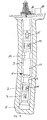
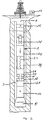
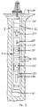
- the drilling devices with devices according to the invention illustrated in the drawing each comprise a drill string, designated as a whole as 1, with an inner channel 2 and an annular space 3 surrounding the drill pipe string 1.
- the drill string 1 is used for directional drilling.
- the drill string 1 in turn has an inner channel 2 and an annular space 3 surrounding the drill string 1.
- flushing liquid is pumped down through the inner channel 2 by means of a pump, not shown, which drives a drilling turbine, not shown, on its way to the bottom of the borehole and exits into the borehole through nozzles of the rotary drill bit 5 driven by the drilling turbine and returns to the earth's surface through the annular space 3 surrounding the drill pipe string.
- a sensor 7 for inclination and direction measurement data is arranged above the rotary drill bit 5 and is connected to the structure-borne sound transmitter 11.
- a joint piece 13 is present between the structure-borne sound transmitter 11 carrying drill pipe and the underground drilling motor 12 with flushing drive. Another joint piece 13 is provided between the motor 12 and the drill pipe carrying the structure-borne sound receiver 14.
- the inclination and direction measurement data determined by the sensor 7 are transmitted from the transmitter 11 to the receiver 14 by structure-borne noise.
- a pressure pulse transmitter 15 of a known type is arranged above the receiver 14 and forwards the signals received by the receiver 14 to the pressure pulse receiver 16 via a further transmission path which is formed by the flushing liquid in the inner tube 2. These are evaluated in processor 10 after conversion into electrical signals.
- a first sensor 17 for determining contact pressure signals is arranged above the rotary drill bit 5 of the drill string 1. This is galvanically connected to a coil former 18.
- the coil former 18 is a transmitter for magnetically inductive transmission of the received signals to a coil former 20 coupled to the coil 18 via the free air gap 19, which coil therefore represents the receiver of this magnetically inductive transmission path, so that the data transmission from the rotating parts 5, 17 is contactless and the outer tube 21 of the drill string 1 carrying the bobbin 18 onto the non-rotating drill pipe wall parts 22 and the drill motor 23 connected thereto.
- the signals from the sensor 17 are transmitted via the underground motor 23 by means of galvanic coupling a cable connection 24 is forwarded to an inclination and direction sensor 25.
- the measurement data generated in the two sensor units 17 and 25 are then passed on together from the pressure pulse transmitter unit via the flushing liquid column in channel 2 of the drill pipe in a known manner to the pressure pulse receiver 16 and from there via a cable connection to the processor after conversion into electrical signals.
- an inclination and direction sensor is connected both to a pressure pulse transmitter 27 for transmitting the inclination and direction measurement signals to the pressure pulse receiver 28 and forwarded to the processor 10 after conversion into electrical signals, and also to a structure-borne sound transmitter via a cable connection 29 30 for short-range data transmission to a structure-borne sound receiver 31.
- a pressure pulse transmitter 27 for transmitting the inclination and direction measurement signals to the pressure pulse receiver 28 and forwarded to the processor 10 after conversion into electrical signals
- a structure-borne sound transmitter via a cable connection 29 30 for short-range data transmission to a structure-borne sound receiver 31.
- antimagnetic collars 32 so as not to influence the inclination and direction data determination with the aid of magnetically sensitive sensors.
- control signals transmitted from the inclination and direction sensor 26 via structure-borne sound to the structure-borne sound receiver 31 are given to the directional drilling tool 34 via a cable connection 33, so that control movements as long as deviations occur between a predetermined direction or inclination and the actual values detected by the sensor 26 are to be carried out until the deviation has decreased within a specifiable tolerance range.
- transmission devices and sensors in general may require further electronic components for signal processing as well as batteries or generators driven by the drilling fluid or revolving drill string parts for generating electrical energy, which, however, are known per se and are provided in a suitable manner can.
Landscapes
- Engineering & Computer Science (AREA)
- Physics & Mathematics (AREA)
- Life Sciences & Earth Sciences (AREA)
- Geology (AREA)
- Mining & Mineral Resources (AREA)
- General Life Sciences & Earth Sciences (AREA)
- Geochemistry & Mineralogy (AREA)
- Environmental & Geological Engineering (AREA)
- Fluid Mechanics (AREA)
- Remote Sensing (AREA)
- Geophysics (AREA)
- Mechanical Engineering (AREA)
- Acoustics & Sound (AREA)
- Electromagnetism (AREA)
- Arrangements For Transmission Of Measured Signals (AREA)
- Selective Calling Equipment (AREA)
- Near-Field Transmission Systems (AREA)
- Cable Transmission Systems, Equalization Of Radio And Reduction Of Echo (AREA)
Abstract
Claims (17)
- Dispositif pour la transmission de signaux de données et/ou de commande dans un train de tiges de forage (1) pendant le fonctionnement d'un outil de forage comprenant un trépan (5), en particulier pour la transmission de signaux de données et/ou de commande du forage à la surface du sol, comprenant au moins une unité de saisie de données et/ou de commande qui peut être prévue sur le train de tiges (1) et un processeur (10), étant entendu que les signaux de données et/ou de commande entre le processeur (10) et l'unité de saisie de données ou de commande sont acheminés par une liaison de transmission depuis un émetteur jusqu'à un récepteur, que la liaison de transmission servant pour la transmission de signaux de données et/ou de commande entre l'émetteur et le récepteur comprend des coupleurs à induction magnétique associés l'un à l'autre (18, 20) ou des capteurs/récepteurs de son associés l'un à l'autre (8, 9, 11, 14, 30, 31), que les signaux de données et/ou de commande reçus par le récepteur (20) de la liaison de transmission sont transmis à un émetteur (15) d'une autre liaison de transmission et l'émetteur (15) de l'autre liaison de transmission transmet les signaux reçus au récepteur (16) de l'autre liaison de transmission, caractérisé en ce que les coupleurs à induction magnétique associés l'un à l'autre (18, 20) ou les capteurs/récepteurs de son (8, 9, 11, 14, 30, 31) sont montés sur des zones du train de tiges pouvant tourner l'une par rapport à l'autre et les signaux de données et de commande sont transmis sans contact, d'une zone à l'autre zone de train de tiges, la transmission ultérieure des signaux de données et de commande s'effectuant via des signaux d'impulsions de pression ou via une liaison galvanique.
- Dispositif suivant la revendication 1, caractérisé en ce que des coupleurs à induction magnétique train de tiges (1) peuvent être reliés par voie galvanique, par l'intermédiaire d'une liaison de câbles (39, 40) et/ou des parties de paroi de tubes conductrices de l'électricité.
- Dispositif suivant la revendication 2, caractérisé en ce que les coupleurs à induction magnétique (18, 20) sont conçus comme des corps de bobine et/ou des capteurs à semi-conducteurs sensibles au champ magnétique, disposés dans les zones d'extrémité de tubes se faisant face (35, 36) du train de tiges (1).
- Dispositif suivant la revendication 3, caractérisé en ce que les coupleurs à induction magnétique (18, 20) disposés dans les zones d'extrémité des tubes (35, 36) du train de tiges se font face librement et sont couplés en transformateur.
- Dispositif suivant la revendication 1, caractérisé en ce que les coupleurs à induction magnétique (18, 20) peuvent être prévus à une certaine distance face aux parties de paroi de tube voisines, conductrices de l'électricité.
- Dispositif suivant l'une quelconque des revendications 1 à 5, caractérisé en ce que la liaison de transmission comprenant les coupleurs à induction magnétique (18, 20) est associée à une autre liaison de transmission comprenant son propre émetteur (15) et son propre récepteur (16).
- Dispositif suivant la revendication 6, caractérisé en ce que l'émetteur (15) de l'autre liaison de transmission peut être alimenté par les signaux de données et/ou de commande provenant de la première liaison de transmission.
- Dispositif suivant la revendication 6 ou 7, caractérisé en ce que l'autre liaison de transmission est formée par une boue de rinçage de l'outil de forage, qui transmet des impulsions de pression depuis l'autre émetteur (15).
- Dispositif suivant la revendication 1, caractérisé en ce que les données reçues par le capteur de son (8) sont transmises sous forme de signaux ultrasonores au récepteur de son (9).
- Dispositif suivant la revendication 1, caractérisé en ce que les signaux de données reçus par le capteur de son (11, 30) sont transmis sous forme de signaux sonores dans les solides au récepteur de son (14, 31).
- Dispositif suivant la revendication 10, caractérisé en ce que les signaux sonores dans les solides sont transmis au récepteur de son (14, 31) via des parties du train de tiges.
- Dispositif suivant la revendication 9, caractérisé en ce que la liaison de transmission est formée par une boue de rinçage de l'outil de forage et les signaux sonores sont transmis via la boue de rinçage.
- Dispositif suivant la revendication 8 ou 9, caractérisé en ce que la liaison de transmission est formée par une colonne d'air située à l'intérieur du train de tiges et les signaux sonores sont transmis via la colonne d'air depuis le capteur de son au récepteur de son (9).
- Dispositif suivant l'une quelconque des revendications 8 à 13, caractérisé en ce que les signaux sonores reçus par le récepteur de son (9, 14, 31) de la liaison de transmission sont transmis à un émetteur (15) d'une autre liaison de transmission suivante et de là, à un récepteur propre (16) de l'autre liaison de transmission.
- Dispositif suivant la revendication 14, caractérisé en ce que les signaux sonores reçus de l'émetteur (15) de l'autre liaison de transmission sont transmis sous forme de signaux d'impulsions de pression.
- Dispositif suivant la revendication 1, caractérisé en ce que des amplificateurs de signaux sont prévus entre le capteur de son (8, 11, 31) et le récepteur de son (9, 14, 30).
- Dispositif suivant la revendication 1, caractérisé en ce que des transducteurs en polyéthylène sont fixés à des parties de paroi interne du train de tiges à titre d'émetteur et de récepteur de signaux sonores.
Applications Claiming Priority (3)
| Application Number | Priority Date | Filing Date | Title |
|---|---|---|---|
| DE3916704A DE3916704A1 (de) | 1989-05-23 | 1989-05-23 | Signaluebertragung in bohrgestaengen |
| DE3916704 | 1989-05-23 | ||
| PCT/EP1990/000837 WO1990014497A2 (fr) | 1989-05-23 | 1990-05-23 | Procede et dispositif pour transmettre des signaux de donnees et/ou de commande dans un tubage |
Publications (2)
| Publication Number | Publication Date |
|---|---|
| EP0426820A1 EP0426820A1 (fr) | 1991-05-15 |
| EP0426820B1 true EP0426820B1 (fr) | 1996-01-17 |
Family
ID=6381197
Family Applications (2)
| Application Number | Title | Priority Date | Filing Date |
|---|---|---|---|
| EP90870079A Withdrawn EP0399987A1 (fr) | 1989-05-23 | 1990-05-22 | Appareil et procédé pour transmettre un signal dans la tige de forage |
| EP90908523A Expired - Lifetime EP0426820B1 (fr) | 1989-05-23 | 1990-05-23 | Procede et dispositif pour transmettre des signaux de donnees et/ou de commande dans un tubage |
Family Applications Before (1)
| Application Number | Title | Priority Date | Filing Date |
|---|---|---|---|
| EP90870079A Withdrawn EP0399987A1 (fr) | 1989-05-23 | 1990-05-22 | Appareil et procédé pour transmettre un signal dans la tige de forage |
Country Status (3)
| Country | Link |
|---|---|
| EP (2) | EP0399987A1 (fr) |
| DE (1) | DE3916704A1 (fr) |
| WO (1) | WO1990014497A2 (fr) |
Cited By (1)
| Publication number | Priority date | Publication date | Assignee | Title |
|---|---|---|---|---|
| US7163065B2 (en) | 2002-12-06 | 2007-01-16 | Shell Oil Company | Combined telemetry system and method |
Families Citing this family (49)
| Publication number | Priority date | Publication date | Assignee | Title |
|---|---|---|---|---|
| DE3916704A1 (de) * | 1989-05-23 | 1989-12-14 | Wellhausen Heinz | Signaluebertragung in bohrgestaengen |
| US5160925C1 (en) * | 1991-04-17 | 2001-03-06 | Halliburton Co | Short hop communication link for downhole mwd system |
| JP2766747B2 (ja) * | 1991-10-25 | 1998-06-18 | 株式会社三井造船昭島研究所 | 坑底情報収集装置 |
| CA2127921A1 (fr) * | 1993-07-26 | 1995-01-27 | Wallace Meyer | Methode et appareil de telemetrie electrique/acoustique |
| EP0721053A1 (fr) * | 1995-01-03 | 1996-07-10 | Shell Internationale Researchmaatschappij B.V. | Système de fond de puits pour la transmission de l'électricité |
| FR2757718B1 (fr) * | 1996-12-23 | 1999-02-12 | Setmat | Equipements de transmission electromagnetique pour tuyaux flexibles de livraison de produits fluides |
| GB2341754B (en) | 1998-09-19 | 2002-07-03 | Cryoton | Drill string telemetry |
| US6347292B1 (en) | 1999-02-17 | 2002-02-12 | Den-Con Electronics, Inc. | Oilfield equipment identification method and apparatus |
| US6670880B1 (en) | 2000-07-19 | 2003-12-30 | Novatek Engineering, Inc. | Downhole data transmission system |
| US7040003B2 (en) | 2000-07-19 | 2006-05-09 | Intelliserv, Inc. | Inductive coupler for downhole components and method for making same |
| CA2416053C (fr) | 2000-07-19 | 2008-11-18 | Novatek Engineering Inc. | Systeme de transmission de donnees pour fond de trou |
| US7098767B2 (en) | 2000-07-19 | 2006-08-29 | Intelliserv, Inc. | Element for use in an inductive coupler for downhole drilling components |
| US6866306B2 (en) | 2001-03-23 | 2005-03-15 | Schlumberger Technology Corporation | Low-loss inductive couplers for use in wired pipe strings |
| US6641434B2 (en) | 2001-06-14 | 2003-11-04 | Schlumberger Technology Corporation | Wired pipe joint with current-loop inductive couplers |
| FR2829889B1 (fr) * | 2001-09-20 | 2004-04-02 | Setmat | Insertion d'une bobine a air d'une ligne de transmission electromagnetique a l'interieur de chaque joint d'etancheite des deux coupleurs d'extremite d'un element de tuyau flexible |
| NO315068B1 (no) * | 2001-11-12 | 2003-06-30 | Abb Research Ltd | En innretning for elektrisk kobling |
| US7243717B2 (en) | 2002-08-05 | 2007-07-17 | Intelliserv, Inc. | Apparatus in a drill string |
| US6799632B2 (en) | 2002-08-05 | 2004-10-05 | Intelliserv, Inc. | Expandable metal liner for downhole components |
| US7224288B2 (en) | 2003-07-02 | 2007-05-29 | Intelliserv, Inc. | Link module for a downhole drilling network |
| US7098802B2 (en) | 2002-12-10 | 2006-08-29 | Intelliserv, Inc. | Signal connection for a downhole tool string |
| US6830467B2 (en) | 2003-01-31 | 2004-12-14 | Intelliserv, Inc. | Electrical transmission line diametrical retainer |
| US6844498B2 (en) | 2003-01-31 | 2005-01-18 | Novatek Engineering Inc. | Data transmission system for a downhole component |
| US7852232B2 (en) | 2003-02-04 | 2010-12-14 | Intelliserv, Inc. | Downhole tool adapted for telemetry |
| US7096961B2 (en) | 2003-04-29 | 2006-08-29 | Schlumberger Technology Corporation | Method and apparatus for performing diagnostics in a wellbore operation |
| US6913093B2 (en) | 2003-05-06 | 2005-07-05 | Intelliserv, Inc. | Loaded transducer for downhole drilling components |
| US6929493B2 (en) | 2003-05-06 | 2005-08-16 | Intelliserv, Inc. | Electrical contact for downhole drilling networks |
| US7053788B2 (en) | 2003-06-03 | 2006-05-30 | Intelliserv, Inc. | Transducer for downhole drilling components |
| US6981546B2 (en) | 2003-06-09 | 2006-01-03 | Intelliserv, Inc. | Electrical transmission line diametrical retention mechanism |
| US6950034B2 (en) | 2003-08-29 | 2005-09-27 | Schlumberger Technology Corporation | Method and apparatus for performing diagnostics on a downhole communication system |
| US7019665B2 (en) | 2003-09-02 | 2006-03-28 | Intelliserv, Inc. | Polished downhole transducer having improved signal coupling |
| US6991035B2 (en) | 2003-09-02 | 2006-01-31 | Intelliserv, Inc. | Drilling jar for use in a downhole network |
| US7040415B2 (en) | 2003-10-22 | 2006-05-09 | Schlumberger Technology Corporation | Downhole telemetry system and method |
| US7017667B2 (en) | 2003-10-31 | 2006-03-28 | Intelliserv, Inc. | Drill string transmission line |
| US6968611B2 (en) | 2003-11-05 | 2005-11-29 | Intelliserv, Inc. | Internal coaxial cable electrical connector for use in downhole tools |
| US6945802B2 (en) | 2003-11-28 | 2005-09-20 | Intelliserv, Inc. | Seal for coaxial cable in downhole tools |
| US7291303B2 (en) | 2003-12-31 | 2007-11-06 | Intelliserv, Inc. | Method for bonding a transmission line to a downhole tool |
| US7069999B2 (en) | 2004-02-10 | 2006-07-04 | Intelliserv, Inc. | Apparatus and method for routing a transmission line through a downhole tool |
| US7413021B2 (en) | 2005-03-31 | 2008-08-19 | Schlumberger Technology Corporation | Method and conduit for transmitting signals |
| US7913773B2 (en) | 2005-08-04 | 2011-03-29 | Schlumberger Technology Corporation | Bidirectional drill string telemetry for measuring and drilling control |
| JP2009503306A (ja) | 2005-08-04 | 2009-01-29 | シュルンベルジェ ホールディングス リミテッド | 坑井遠隔計測システム用インターフェイス及びインターフェイス方法 |
| US7777644B2 (en) | 2005-12-12 | 2010-08-17 | InatelliServ, LLC | Method and conduit for transmitting signals |
| US8857510B2 (en) | 2009-04-03 | 2014-10-14 | Schlumberger Technology Corporation | System and method for determining movement of a drilling component in a wellbore |
| US9063250B2 (en) | 2009-08-18 | 2015-06-23 | Schlumberger Technology Corporation | Interference testing while drilling |
| US8851175B2 (en) * | 2009-10-20 | 2014-10-07 | Schlumberger Technology Corporation | Instrumented disconnecting tubular joint |
| US8192213B2 (en) | 2009-10-23 | 2012-06-05 | Intelliserv, Llc | Electrical conduction across interconnected tubulars |
| US8362915B2 (en) | 2009-10-30 | 2013-01-29 | Intelliserv, Llc | System and method for determining stretch or compression of a drill string |
| DE102010047568A1 (de) | 2010-04-12 | 2011-12-15 | Peter Jantz | Einrichtung zur Übertragung von Informationen über Bohrgestänge |
| US8727035B2 (en) | 2010-08-05 | 2014-05-20 | Schlumberger Technology Corporation | System and method for managing temperature in a wellbore |
| WO2015192226A1 (fr) | 2014-06-18 | 2015-12-23 | Evolution Engineering Inc. | Systèmes, procédé et appareil de mesure pendant le forage |
Family Cites Families (14)
| Publication number | Priority date | Publication date | Assignee | Title |
|---|---|---|---|---|
| US2547875A (en) * | 1936-10-29 | 1951-04-03 | Schlumberger Well Surv Corp | Apparatus for taking physical measurements in boreholes |
| US2379800A (en) * | 1941-09-11 | 1945-07-03 | Texas Co | Signal transmission system |
| US2414719A (en) * | 1942-04-25 | 1947-01-21 | Stanolind Oil & Gas Co | Transmission system |
| US3090031A (en) * | 1959-09-29 | 1963-05-14 | Texaco Inc | Signal transmission system |
| US3588804A (en) * | 1969-06-16 | 1971-06-28 | Globe Universal Sciences | Telemetering system for use in boreholes |
| FR2165074A5 (fr) * | 1971-12-16 | 1973-08-03 | Drogo Pierre | |
| IN142419B (fr) * | 1973-08-23 | 1977-07-02 | Sun Oil Co | |
| US4293936A (en) * | 1976-12-30 | 1981-10-06 | Sperry-Sun, Inc. | Telemetry system |
| US4314365A (en) * | 1980-01-21 | 1982-02-02 | Exxon Production Research Company | Acoustic transmitter and method to produce essentially longitudinal, acoustic waves |
| US4605268A (en) * | 1982-11-08 | 1986-08-12 | Nl Industries, Inc. | Transformer cable connector |
| GB8619316D0 (en) * | 1986-08-07 | 1986-09-17 | Thorburn Technics Int | Rotary signal coupler |
| FR2617901B1 (fr) * | 1987-07-06 | 1989-10-27 | Alsthom | Procede de forage avec transmission electromagnetique d'informations depuis le fond |
| FR2627649B1 (fr) * | 1988-02-22 | 1990-10-26 | Inst Francais Du Petrole | Methode et dispositif de transmission de l'information par cable et par ondes de boue |
| DE3916704A1 (de) * | 1989-05-23 | 1989-12-14 | Wellhausen Heinz | Signaluebertragung in bohrgestaengen |
-
1989
- 1989-05-23 DE DE3916704A patent/DE3916704A1/de not_active Withdrawn
-
1990
- 1990-05-22 EP EP90870079A patent/EP0399987A1/fr not_active Withdrawn
- 1990-05-23 WO PCT/EP1990/000837 patent/WO1990014497A2/fr not_active Ceased
- 1990-05-23 EP EP90908523A patent/EP0426820B1/fr not_active Expired - Lifetime
Cited By (2)
| Publication number | Priority date | Publication date | Assignee | Title |
|---|---|---|---|---|
| US7163065B2 (en) | 2002-12-06 | 2007-01-16 | Shell Oil Company | Combined telemetry system and method |
| US7565936B2 (en) | 2002-12-06 | 2009-07-28 | Shell Oil Company | Combined telemetry system and method |
Also Published As
| Publication number | Publication date |
|---|---|
| EP0426820A1 (fr) | 1991-05-15 |
| WO1990014497A2 (fr) | 1990-11-29 |
| DE3916704A1 (de) | 1989-12-14 |
| EP0399987A1 (fr) | 1990-11-28 |
| WO1990014497A3 (fr) | 1991-01-10 |
Similar Documents
| Publication | Publication Date | Title |
|---|---|---|
| WO1990014497A2 (fr) | Procede et dispositif pour transmettre des signaux de donnees et/ou de commande dans un tubage | |
| DE3789145T2 (de) | Einrichtung zur Datenübertragung in einem Bohrloch mit einem magnetischen Bohrgestänge. | |
| DE69112409T2 (de) | Datenübertragung in bohrlöchern. | |
| DE69502274T2 (de) | Gaslift-system mit einem auswechselbaren hubventil | |
| US8519865B2 (en) | Downhole coils | |
| EP0232891B1 (fr) | Outil de forage pour puits profonds | |
| DE69914838T2 (de) | Formationsdruckmessung mit Fernsensoren in verrohrten Bohrlöchern | |
| DE60032920T2 (de) | Vorrichtung zur übertragung von elektrische energie zwischen rotierenden und nicht rotierenden teilen von bohrlochwerkzeugen | |
| DE3882221T2 (de) | Kommunikationsanordnung für ein seismisches Messkabel. | |
| DE4291022B4 (de) | Kurzstreckenübertragungsverbindung für ein Tiefen-MWD-System | |
| DE602004001903T2 (de) | Piezoelektrischer und magnetostriktiver Hybrid-Aktor | |
| DE69800636T2 (de) | Gerät und System für Bohrlochmessungen nahe dem Bohrer während des Bohrens | |
| EP0134467B1 (fr) | Tige de forage dirigée pour train de tiges rotatif à canal d'injection, pour l'exploitation au fond | |
| DE69815240T2 (de) | Verfahren und Anordnung zur Messung des Widerstandes von Erdformationen | |
| US20080012569A1 (en) | Downhole Coils | |
| DE69314289T2 (de) | System für Messungen während des Bohrens mit Druckpuls-Ventil zur Datenübertragung | |
| DE69212581T2 (de) | Verfahren und Einrichtung zur elektrischen Verbindung von Geräten wie Bohrlochsonden | |
| DE2848722A1 (de) | Telemetriesystem | |
| DE69221422T2 (de) | System für Messungen während des Bohrens | |
| DE102005014708A1 (de) | Lateraler Resistivitätssensor und Verfahren zum Anbringen eines lateralen Resistivitätssensors an einem Rohrabschnitt | |
| DE1238413B (de) | Verfahren und Vorrichtung zur Herstellung einer von der Senkrechten abweichenden Hilfsbohrung | |
| DE102007020662A1 (de) | Induktives Kopplungssystem | |
| DE102007034589A1 (de) | Drahtlose Telemetrie zwischen Bohrlochwerkzeugen | |
| DE102007062230A1 (de) | Hybrid-Telemetriesystem, Hybrid-Datenübertragungssystem und Verfahren zum Leiten von Signalen | |
| DE3435812A1 (de) | Geraet zur messung der drehgeschwindigkeit eines rotierenden elements |
Legal Events
| Date | Code | Title | Description |
|---|---|---|---|
| PUAI | Public reference made under article 153(3) epc to a published international application that has entered the european phase |
Free format text: ORIGINAL CODE: 0009012 |
|
| AK | Designated contracting states |
Kind code of ref document: A1 Designated state(s): BE FR GB NL |
|
| 17P | Request for examination filed |
Effective date: 19910515 |
|
| 17Q | First examination report despatched |
Effective date: 19920512 |
|
| GRAA | (expected) grant |
Free format text: ORIGINAL CODE: 0009210 |
|
| AK | Designated contracting states |
Kind code of ref document: B1 Designated state(s): BE FR GB NL |
|
| PG25 | Lapsed in a contracting state [announced via postgrant information from national office to epo] |
Ref country code: FR Effective date: 19960117 Ref country code: BE Effective date: 19960117 |
|
| GBT | Gb: translation of ep patent filed (gb section 77(6)(a)/1977) |
Effective date: 19960220 |
|
| EN | Fr: translation not filed | ||
| PLBE | No opposition filed within time limit |
Free format text: ORIGINAL CODE: 0009261 |
|
| STAA | Information on the status of an ep patent application or granted ep patent |
Free format text: STATUS: NO OPPOSITION FILED WITHIN TIME LIMIT |
|
| 26N | No opposition filed | ||
| PGFP | Annual fee paid to national office [announced via postgrant information from national office to epo] |
Ref country code: NL Payment date: 19990510 Year of fee payment: 10 |
|
| PG25 | Lapsed in a contracting state [announced via postgrant information from national office to epo] |
Ref country code: NL Free format text: LAPSE BECAUSE OF NON-PAYMENT OF DUE FEES Effective date: 20001201 |
|
| NLV4 | Nl: lapsed or anulled due to non-payment of the annual fee |
Effective date: 20001201 |
|
| REG | Reference to a national code |
Ref country code: GB Ref legal event code: IF02 |
|
| PGFP | Annual fee paid to national office [announced via postgrant information from national office to epo] |
Ref country code: GB Payment date: 20090528 Year of fee payment: 20 |
|
| PG25 | Lapsed in a contracting state [announced via postgrant information from national office to epo] |
Ref country code: GB Free format text: LAPSE BECAUSE OF EXPIRATION OF PROTECTION Effective date: 20100522 |