EP0426976A2 - Cabine démontable transportable - Google Patents
Cabine démontable transportable Download PDFInfo
- Publication number
- EP0426976A2 EP0426976A2 EP90117696A EP90117696A EP0426976A2 EP 0426976 A2 EP0426976 A2 EP 0426976A2 EP 90117696 A EP90117696 A EP 90117696A EP 90117696 A EP90117696 A EP 90117696A EP 0426976 A2 EP0426976 A2 EP 0426976A2
- Authority
- EP
- European Patent Office
- Prior art keywords
- wall
- segment
- cabin
- segments
- door
- Prior art date
- Legal status (The legal status is an assumption and is not a legal conclusion. Google has not performed a legal analysis and makes no representation as to the accuracy of the status listed.)
- Granted
Links
Images

Classifications
-
- E—FIXED CONSTRUCTIONS
- E04—BUILDING
- E04B—GENERAL BUILDING CONSTRUCTIONS; WALLS, e.g. PARTITIONS; ROOFS; FLOORS; CEILINGS; INSULATION OR OTHER PROTECTION OF BUILDINGS
- E04B1/00—Constructions in general; Structures which are not restricted either to walls, e.g. partitions, or floors or ceilings or roofs
- E04B1/348—Structures composed of units comprising at least considerable parts of two sides of a room, e.g. box-like or cell-like units closed or in skeleton form
- E04B1/34869—Elements for special technical purposes, e.g. with a sanitary equipment
-
- A—HUMAN NECESSITIES
- A47—FURNITURE; DOMESTIC ARTICLES OR APPLIANCES; COFFEE MILLS; SPICE MILLS; SUCTION CLEANERS IN GENERAL
- A47K—SANITARY EQUIPMENT; ACCESSORIES THEREFOR, e.g. TOILET ACCESSORIES
- A47K4/00—Combinations of baths, showers, sinks, wash-basins, closets, or urinals, not covered by a single other group of this subclass
-
- E—FIXED CONSTRUCTIONS
- E04—BUILDING
- E04H—BUILDINGS OR LIKE STRUCTURES FOR PARTICULAR PURPOSES; SWIMMING OR SPLASH BATHS OR POOLS; MASTS; FENCING; TENTS OR CANOPIES, IN GENERAL
- E04H1/00—Buildings or groups of buildings for dwelling or office purposes; General layout, e.g. modular co-ordination or staggered storeys
- E04H1/12—Small buildings or other erections for limited occupation, erected in the open air or arranged in buildings, e.g. kiosks, waiting shelters for bus stops or for filling stations, roofs for railway platforms, watchmen's huts or dressing cubicles
- E04H1/1205—Small buildings erected in the open air
- E04H1/1216—Public W.C.s
-
- Y—GENERAL TAGGING OF NEW TECHNOLOGICAL DEVELOPMENTS; GENERAL TAGGING OF CROSS-SECTIONAL TECHNOLOGIES SPANNING OVER SEVERAL SECTIONS OF THE IPC; TECHNICAL SUBJECTS COVERED BY FORMER USPC CROSS-REFERENCE ART COLLECTIONS [XRACs] AND DIGESTS
- Y02—TECHNOLOGIES OR APPLICATIONS FOR MITIGATION OR ADAPTATION AGAINST CLIMATE CHANGE
- Y02A—TECHNOLOGIES FOR ADAPTATION TO CLIMATE CHANGE
- Y02A50/00—TECHNOLOGIES FOR ADAPTATION TO CLIMATE CHANGE in human health protection, e.g. against extreme weather
- Y02A50/30—Against vector-borne diseases, e.g. mosquito-borne, fly-borne, tick-borne or waterborne diseases whose impact is exacerbated by climate change
Definitions
- the present invention relates to a cabin, which consists of several wall segments and optionally at least one ceiling and one floor segment, which can be assembled into an essentially closed cabin.
- the present invention also relates to a method for producing a cabin that can be assembled from several segments.
- Cabins which can be assembled from several segments, for example designed as portable toilet cabins for chemical toilets, which can be set up at short notice as required, are known. These consist essentially of four wall panels, a floor and a ceiling panel, these parts being riveted together to form a cuboid-shaped cabin.
- the object of the invention is to provide a cabin with the features mentioned at the outset and a method for producing such a cabin create, which enable a significantly simplified manufacture and assembly of the cabin and at the same time ensure a stable and relatively torsion-resistant cohesion and an attractive exterior of the cabin.
- the cabin should also be easy to disassemble and easy to transport, if possible.
- this object is achieved in that the segments from which the cabin can be assembled are at least partially produced as demoldable hollow blow molded parts with essentially the same outer outline.
- the production of the segments as hollow blow parts contributes to an enormous acceleration of the production process, whereby the constructional structure as hollow blow parts brings with it a whole series of further advantages.
- the hollow blow parts can be manufactured relatively dimensionally stable and, as double-walled parts, have both heat and sound insulation.
- Hollow blowing is understood to mean a manufacturing process in which a more or less large “drop” or lump made of a flowable plastic material is arranged at a nozzle opening, introduced into a cavity with the desired negative shape and inflated from the inside, so that the Apply plastic material from the inside to the walls of the mold.
- a plurality of “drops” can also be introduced into a mold which, after inflation, form an integrally connected molded part with a plurality of separate cavities.
- plastic cabins are already known, but their walls are generally not composed of segments and which are produced by a centrifuging process. However, the corresponding forms are not very durable, so that you can only produce comparable small quantities with it. In addition, the plastic material is heated relatively high twice in this manufacturing process and is thereby burdened accordingly.
- segmentation of the cabin has the advantage that one and the same shape or a part of a shape can be used in succession for several segments of a cabin. This saves costs for molds, which are generally considerable.
- An essential element of the invention is that the cabin not only consists of several individual segments, but that these segments can be assembled very quickly and easily and can also be dismantled again quickly, for example for transport to another location.
- hollow blow parts are their stability as double-walled parts, so that on an additional support structure or individual support elements, for. B. made of metal, can be dispensed with.
- three wall segments forming the outer wall of the cabin are assembled via tongue-and-groove connections and provided with at least one essentially horizontally circumferential tensioning strap.
- the door of the cabin is produced in one piece with the associated wall segment as a hollow blown part, the door having a cavity which is separate from the rest of the wall segment and is connected to the remaining wall segments via a generally solid web, the door being separated from the segment to form a door opening along the web.
- An embodiment of the invention is preferred in which the door is separated from the wall segment along a completely circumferential web, provided with at least one hinge element on one longitudinal edge, and is offset with an overlap in the resulting door opening, essentially over the width of the hinge element, the Hinge element is attached to the edge of the door opening of the wall segment facing it.
- the object on which the invention is based is achieved in that at least some of the wall segments consist of at least one its outside in plan essentially straight first wall part and at least one at an angle of at most 90 ° to this angled and firmly connected to the first wall part second wall part.
- These two wall parts are preferably produced as a one-piece, angled wall segment.
- segments consisting of at least two wall parts with a fixed angle between the two wall parts
- simple flat segments consisting of only one wall part can also be used if on the inside thereof, for example as a floor or ceiling segment Shaped part is arranged, which also specifies the relative angle of the individual wall segments to each other and wherein the segments are held together from the outside by a tension band and pressed against the inner molded part.
- At least a part of the wall segments is produced as a hollow blow part.
- Hollow blow parts have the advantageous properties already mentioned with regard to their manufacturability but also with regard to the strength that can be achieved with a comparatively low weight, so that the cabin is correspondingly stable and at the same time light, which in turn facilitates transport.
- a suitable material for hollow blowing is, for example, polyethylene that has good impact resistance even in the cold.
- An embodiment of the invention is preferred in which some of the segments on the inside have the same basic shape or plan shape as on the outside.
- the wall segments can be stacked on top of one another in a space-saving manner by placing one wall segment with its outside on the inside of another wall segment, since this inside is essentially the one has the same basic shape.
- an embodiment of the cabin is preferred in which the individual wall segments from which the cabin is composed can be stacked in this way.
- the wall segments should have additional elements formed on the inside, the walls of which, from the visible inside, enclose an angle of at least about 60 ° or greater with the inside surface of the first and / or second wall part.
- the stackability is adversely affected by the arrangement of additional elements on the inner surface of a wall segment, but since these additional elements are limited to only a part, and preferably only to a single wall segment, all other wall segments can be stacked on top of one another and finally the wall segment can be stacked on the inside molded additional elements are placed on this stack.
- the walls of the additional elements with the inner surface of the first and / or second wall part must not form too small an angle, since otherwise the demouldability of such parts is not guaranteed.
- two molded parts are placed next to one another in the case of hollow blowing, with the formation of one or more intermediate cavities. So that after the blowing out of the cavities thus formed, it is possible to remove the molds without destroying or damaging the hollow part produced, the two mold halves must not be in the demolding direction, that is, in the direction in which the molds are pulled apart undercut protrusions.
- the additional elements or their walls must be shaped in such a way that there is at least one viewing direction (which then also corresponds to the demolding direction), from which none of the walls of the additional elements appear undercut. From this line of sight, all the walls of the additional elements and additionally the inside of the wall parts of the wall segment are visible or run at most parallel to the line of sight.
- each wall segment has two second wall parts attached to opposite edges of the first wall part and, if applicable, additional elements molded onto the inside of the wall segment, the included angle between the walls is these Additional elements and the first and / or second wall parts at least about 90 °.
- an embodiment of the invention is preferred in which the assembled wall segments are held together by at least one circumferential tensioning strap.
- cohesion with such a tensioning strap enables the cabin to be assembled and disassembled very quickly and, at the same time, ensures that the wall segments are firmly held together, and assembly and disassembly can be carried out entirely without tools.
- the cabin has three wall segments, each consisting of a first wall part which is essentially flat on the outside and second wall parts which are angled at 60.degree., Each of which has approximately half the width of the first wall part.
- the 60 ° angle of the wall parts of each wall segment contributes significantly to the stabilization of the individual wall segments and thus the entire cabin.
- a cabin consisting exclusively of these three wall segments can be put together with its second side parts to form a cabin with the layout of a regular hexagon.
- the second side parts of adjoining wall segments are aligned.
- the regular hexagon shape then results necessarily from the angles of 60 ° included between the first and second wall parts and from the fact that the two abutting side parts of adjacent wall segments are flush with one another and each have half the side length of a first wall part.
- the second wall parts of different segments can abut in a tongue and groove connection.
- the individual wall segments are fixed against each other.
- the wall segments also each have an essentially horizontally extending depression close to their upper and / or lower edge for receiving a tensioning strap each.
- the arrangement of the tensioning straps on the upper and / or lower edge of the cabin is expedient because the passage through a door in the cabin wall is not hindered by the circumferential tensioning strap. If necessary, a single upper or lower strap is sufficient, for example on the opposite one Edge of the cabin the segments are held together by a ceiling or floor element.
- the invention provides that a toilet bowl and / or at least one water tank and / or a sink and / or a urinal are formed as an additional element.
- the cabin has at least one floor segment and / or a ceiling segment in addition to the wall segments.
- the base segment is advantageously hexagonal, its outer dimensions being the inner dimension
- the floor segment is then firmly connected to the wall segments by these projections, so that the cabin as a whole can be raised without the floor segment falling out.
- Such a floor segment corresponds to the molding mentioned above and defined in claim 6, to which the wall segments are pressed by a circumferential tensioning band.
- the bottom segment is also preferably a hollow blown part manufactured and has a cavity designed as a holding tank for the use of the cabin as a toilet.
- the essentially flat design of the walls does not rule out that they are profiled to increase their stability, which is why such an embodiment is preferable.
- a roof segment When a roof segment is used, it can advantageously have a snap edge or clips which spring-engage behind an upper edge of the wall segments.
- the roof segment thus holds the wall segments firmly together and, on the other hand, is also securely fastened to the wall segments, so that it cannot be torn off the wall segments by strong wind or storm.
- the snap edge does not have to be completely circumferential, but individual elastic snap hooks or tensioning hooks can also be provided, with which the roof segment can be connected to the wall segments in a simple and quick manner.
- the roof segment is preferably provided with ventilation slots and / or window inserts.
- the door of the cabin is also made as a hollow blown part which is provided with a hinge element on one edge and overlaps the edge of a door opening with its opposite edge.
- the same advantages result for the manufacture of the door as for the manufacture of the individual wall segments.
- the hinge edge of the door expediently has a profile rail which is undercut parallel to the door edge and which can be inserted into a suitable hollow profile of at least one hinge element. This measure also contributes to simplifying the manufacturing process. It is also expedient if a spring element is provided on the door and on the associated wall segment, which prestresses the door in the closed position.
- recesses for receiving hinge pins are provided in the bottom segment and / or in the ceiling segment. In this way you can save yourself the attachment of additional hinge elements on the edge of the door opening.
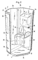
- Figure 1 one can see three wall segments 1, 2 and 3 arranged one behind the other as well as a ceiling segment 5 and a floor segment 4.
- the individual wall segments 1, 2, 3 each consist of a straight first wall part 1 ', 2 which is at least essentially flat on its outside 'Or 3' and from two at an angle of about 60 ° on both sides of the first wall part attaching second wall parts 1a, 1b; 2a, 2b and 3a, 3b.
- the wall part 1 'of the segment 1 has a door opening 12. Otherwise, however, the inner wall of the wall segment 1 essentially (apart from profiling) runs like the inner wall of the wall segment 2 parallel to the respective outer wall of the wall segment 1 or 2.
- the wall segment 3 has various, integrally molded additional elements on its inside, which specifically a water tank 15, another water tank 16, a toilet bowl 17 and a combination container 18 are. Additional attached parts are the toilet lid 34, the water tap 35 and the urinal insert 18 ', which can be clearly seen in FIG. 2 and which can optionally be replaced by a sink insert.
- the walls, for example the wall 15 ', of the additional elements with the inner walls of the wall segment 3 include angles ⁇ and ⁇ which are at least 90 °.
- the walls of the additional elements also abut one another at angles of at least 90 °, so that easy demolding is ensured.
- openings are simply left open or cut out in the additional part, in which appropriate inserts can then be inserted. The same applies to the toilet bowl 17.
- the second wall parts 1a, b; 2a, b and 3a, b are plugged together via tongue and groove connections, the second wall parts marked here with a having the tongue 8, while the second wall parts marked with b have a corresponding groove 9.
- the peripheral edge of the base segment 4 partially shows in
- the projection 24, which is shown in Figure 2 can engage in a corresponding recess at the lower edge of a first wall part, in this case the wall part 1, while the shorter projections 24, two of which are each on the edge of the bottom segment 4 in Figure 1, can each engage in a corresponding recess in the shorter second wall parts.
- the floor segment is also raised in the area of the toilet bowl 17 and has a holding tank 25 below this height.
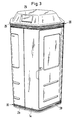
- a completely assembled cabin can be seen from the outside in FIG. 3, the cover segment 5 with its outer snap edge 26 engaging behind the upper edge 27 of the wall segments which can be seen in FIG.
- a tensioning strap 20 is arranged in the depression 21 below, as is the case in the lower depression 21.
- the tensioning strap can be riveted or crimped or can also be releasably tensioned.
- a particular advantage of this clamping technology in connection with the special wall segments is that the stacked wall segments abut each other in such a way that two second wall parts, for example 1a, 2b; 2a, 3b and 3a, 1b are aligned.
- the floor segment 4 is also adapted in its floor plan to the inner dimension of the composite wall segments, so that under the train of the lower tension band 20 an extremely stable cohesion of all segments is guaranteed.
- the cover segment 5 can also have on its underside an edge strip corresponding to the inner dimensions of the wall segments 1, 2, 3, against which the wall segments can rest with their upper inner surface under the tension of the tensioning band 20.
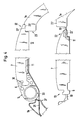
- FIG. 4 shows in the lower part of the drawing a section and interrupted the wall segment 1 with the door 7 formed integrally therewith of the wall part 1, which, after the door 7 has been separated, form two opposite inner edges of a door opening 12.
- the cavity 11 of the door 7 can be recognized by the top of the door 7, shown partially broken away.
- the door 7 is separated from the webs 10 directly at its front edge 22 and immediately behind the rear profile rail 6, the webs 10 also subsequently being separated from the opposite edges 23 or 19 of the door opening 12 can be removed.
- a hinge element 14, which has a hollow profile 30 corresponding to the profile of the profile strand or the profile rail 6, is pushed onto the profile rail 6 from above or below.
- the hinge element can either be continuous over the entire length of the profile rail 6 or two or more short hinge elements 14 can be applied to the profile rail 6 from above or below be postponed.
- the hinge element can either be attached to the inner edge 19 of the door opening, but in the preferred embodiment has an upper and a lower hinge pin 33, which can also be continuous, with the lower hinge pin in a recess 32 on the bottom segment 4, which is best in Figure 2 can be seen, and engages an opposite, not shown recess in the lower crossbar 38 of the door opening 12.
- the upper hinge pin 33 engages in a corresponding pin opening in the upper cross member 37 of the door opening 12.
- the ceiling element 5 can optionally also have a cutout corresponding to the cutout 32 of the base segment 4.
- the cabin made of plastic is rounded at the corners and, as can be seen in particular from Figure 3, has a very attractive appearance.
- This appealing exterior is linked to a maximum of functionality; the cabin is very easy to assemble and can also be disassembled very quickly, the individual wall segments can, as shown in FIG. 1, be stacked on top of one another, so that the transportation of such cabins is therefore considerable is simplified, and the cabin held together by straps is extremely stable and resistant overall.
Landscapes
- Engineering & Computer Science (AREA)
- Architecture (AREA)
- Structural Engineering (AREA)
- Public Health (AREA)
- Civil Engineering (AREA)
- Health & Medical Sciences (AREA)
- Physics & Mathematics (AREA)
- Epidemiology (AREA)
- Electromagnetism (AREA)
- Residential Or Office Buildings (AREA)
- Blow-Moulding Or Thermoforming Of Plastics Or The Like (AREA)
- Vehicle Interior And Exterior Ornaments, Soundproofing, And Insulation (AREA)
- Passenger Equipment (AREA)
- Materials For Medical Uses (AREA)
- Transition And Organic Metals Composition Catalysts For Addition Polymerization (AREA)
- Fittings On The Vehicle Exterior For Carrying Loads, And Devices For Holding Or Mounting Articles (AREA)
Applications Claiming Priority (2)
| Application Number | Priority Date | Filing Date | Title |
|---|---|---|---|
| DE3934847 | 1989-10-19 | ||
| DE3934847A DE3934847C2 (de) | 1989-10-19 | 1989-10-19 | Transportable zerlegbare Kabine |
Related Child Applications (1)
| Application Number | Title | Priority Date | Filing Date |
|---|---|---|---|
| EP92116225.1 Division-Into | 1990-09-14 |
Publications (3)
| Publication Number | Publication Date |
|---|---|
| EP0426976A2 true EP0426976A2 (fr) | 1991-05-15 |
| EP0426976A3 EP0426976A3 (en) | 1991-09-11 |
| EP0426976B1 EP0426976B1 (fr) | 1996-02-07 |
Family
ID=6391768
Family Applications (2)
| Application Number | Title | Priority Date | Filing Date |
|---|---|---|---|
| EP92116225A Withdrawn EP0523753A1 (fr) | 1989-10-19 | 1990-09-14 | Cabine démontable et transportable |
| EP90117696A Expired - Lifetime EP0426976B1 (fr) | 1989-10-19 | 1990-09-14 | Cabine démontable transportable |
Family Applications Before (1)
| Application Number | Title | Priority Date | Filing Date |
|---|---|---|---|
| EP92116225A Withdrawn EP0523753A1 (fr) | 1989-10-19 | 1990-09-14 | Cabine démontable et transportable |
Country Status (4)
| Country | Link |
|---|---|
| US (1) | US5093941A (fr) |
| EP (2) | EP0523753A1 (fr) |
| AT (1) | ATE133843T1 (fr) |
| DE (2) | DE3934847C2 (fr) |
Cited By (1)
| Publication number | Priority date | Publication date | Assignee | Title |
|---|---|---|---|---|
| WO1992022713A1 (fr) * | 1991-06-10 | 1992-12-23 | Oy Shippax Ltd | Module de w.c. a cuvette integree a la paroi |
Families Citing this family (24)
| Publication number | Priority date | Publication date | Assignee | Title |
|---|---|---|---|---|
| US5426900A (en) * | 1992-03-11 | 1995-06-27 | Springer; Robert H. | Multi-purpose hexagonal building module |
| GB2271789B (en) * | 1992-10-15 | 1996-12-18 | Portasilo Ltd | Cabin |
| USD382632S (en) | 1995-09-21 | 1997-08-19 | Herms Ronald G | Hand sanitizing and washing station comprising a sink assembly, soap, and paper towel dispensers |
| DE29615324U1 (de) * | 1996-09-03 | 1997-04-03 | Knüllwald Helo Sauna GmbH, 34593 Knüllwald | Fertig montierte, aus 2 Einzelelementen bestehende, rollbare und steckerfertige Saunaanlage in Holzbauweise |
| DE29718793U1 (de) * | 1997-10-22 | 1998-02-12 | IBK Ingenieurbüro Bauer + Kaletka GmbH, 76229 Karlsruhe | Dachmodul für eine Raumzelle, insbesondere Stahlbeton-Garage |
| DE59800220D1 (de) * | 1998-05-19 | 2000-09-07 | Roth Werke Gmbh | Duschkabine |
| US6370706B1 (en) * | 1999-10-13 | 2002-04-16 | Atlas Portable Sanitation Industries, Inc. | Portable sanitation unit |
| US20020194796A1 (en) * | 2001-06-21 | 2002-12-26 | Kress Russell L. | Modular living enclosure |
| US6681413B2 (en) * | 2002-03-05 | 2004-01-27 | Paul E. Weiss | Portable restroom having a removable waste storage container and method therefor |
| US6721967B2 (en) | 2002-07-22 | 2004-04-20 | Earl J. Braxton | Modular portable comfort station |
| US7356968B2 (en) * | 2003-12-22 | 2008-04-15 | The Bilco Company | Polymer composite basement door |
| US20070074464A1 (en) * | 2005-09-09 | 2007-04-05 | U.S. Modular Solutions, Inc. | Systems and methods of constructing, assembling, and moving modular washrooms |
| DE102007007624B4 (de) * | 2007-02-13 | 2008-10-30 | Maschinenbau Und Service Gmbh Ammendorf | Sanitär- bzw. WC-Modul, insbesondere für Fahrzeuge |
| US8042562B1 (en) | 2007-04-16 | 2011-10-25 | Mcdaniel Jr Michael D | Portable shelters, related shelter systems, and methods of their deployment |
| US8038100B2 (en) * | 2007-09-21 | 2011-10-18 | Honda Motor Co., Ltd. | Paneled partition with track for linear and rotational movement |
| USD586474S1 (en) * | 2007-09-21 | 2009-02-10 | Honda Motor Co., Ltd. | Lavatory door |
| DE102008053228A1 (de) * | 2008-10-27 | 2010-04-29 | Lufthansa Technik Ag | Modulare Duschkabine für Flugzeuge |
| US20100180518A1 (en) * | 2009-01-22 | 2010-07-22 | Postlethwaite Sherald D | Emergency Habitat for Catastrophes |
| JP2014076713A (ja) * | 2012-10-10 | 2014-05-01 | Yokohama Rubber Co Ltd:The | 航空機用化粧室ユニット |
| US9097031B2 (en) * | 2013-11-04 | 2015-08-04 | Reed Ricky C | Molded hunting blind |
| US9765542B1 (en) | 2014-02-17 | 2017-09-19 | Timothy A. Broughton | Nestable, stackable portable toilet and method of assembling same |
| EP3048217A3 (fr) | 2015-01-07 | 2016-08-10 | Reaction, Inc. | Abri modulaire et procédé du montage |
| DE102015116585A1 (de) * | 2015-09-30 | 2017-03-30 | Airbus Operations Gmbh | Kompakte Funktionsanordnung in einer Kabine eines Fahrzeugs und Fahrzeug mit einer solchen Funktionsanordnung |
| ES2941973T3 (es) | 2017-09-28 | 2023-05-29 | Satellite Ind Inc | Baño portátil |
Family Cites Families (29)
| Publication number | Priority date | Publication date | Assignee | Title |
|---|---|---|---|---|
| US2120838A (en) * | 1937-06-07 | 1938-06-14 | Rollie A Lawrence | Stave |
| US2260307A (en) * | 1939-01-26 | 1941-10-28 | Starline | Hay silo |
| US2247836A (en) * | 1940-10-14 | 1941-07-01 | Goldbeck Martin | Silo and method of building same |
| US2650368A (en) * | 1950-06-08 | 1953-09-01 | Evans Randolph | Bathroom construction |
| US2820990A (en) * | 1955-05-11 | 1958-01-28 | Robert F Johnson | Demountable building |
| US3277620A (en) * | 1965-04-12 | 1966-10-11 | Elmer W Martin | Demountable building |
| GB1160779A (en) * | 1967-07-25 | 1969-08-06 | Ici Ltd | Improvements in the production of Shaped Articles from Blanks of Thermosplastics Material |
| CA938073A (en) * | 1971-11-22 | 1973-12-11 | W. Tuuri Elmer | Prefabricated and demountable building |
| US3828965A (en) * | 1972-02-29 | 1974-08-13 | Jet Forwarding Inc | Container having resilient support means |
| US3778528A (en) * | 1972-04-27 | 1973-12-11 | I Kushner | Modular building unit and method for making same |
| DE2224461A1 (de) * | 1972-05-19 | 1973-11-29 | Huebner Peter | Sanitaerwandelement |
| US4065885A (en) * | 1972-08-09 | 1978-01-03 | Monogram Industries, Inc. | Portable building structure |
| DE2406478A1 (de) * | 1974-02-11 | 1975-08-21 | Karsten Buentzow | Beduerfnisanstalt, baukastensystem |
| DE2429531B2 (de) * | 1974-06-20 | 1977-08-25 | Moller, Hans Gunter, 2870 Delmenhorst | Verfahren zum herstellen raumgrosser zellen, insbesondere sanitaerzellen, und vorrichtung zur durchfuehrung des verfahrens |
| US4031572A (en) * | 1974-07-31 | 1977-06-28 | Poly San Corporation | Chemical toilet cabana shell section |
| US4233692A (en) * | 1979-10-09 | 1980-11-18 | Sinsley John D | Rest rooms |
| US4305164A (en) * | 1979-10-22 | 1981-12-15 | Thetford Corporation | Portable toilet facility |
| DE3015550C2 (de) * | 1980-04-23 | 1982-09-09 | GELA Gehör-, Lärm- und Arbeitsschutzmittel GmbH, 6056 Heusenstamm | Audiometrie-Kabine |
| DE3023972A1 (de) * | 1980-06-26 | 1982-01-21 | Dyna-Plastik-Werke Gmbh, 5060 Bergisch Gladbach | Bausatz fuer einen behaelter, insbesondere als nothaus |
| DE3033812A1 (de) * | 1980-09-09 | 1982-04-15 | Norbert 5603 Wülfrath Garich | Transportables schutzhaus, insbesondere toilettenkabine |
| US4672779A (en) * | 1981-07-02 | 1987-06-16 | Boyd Clarence J | Portable shelter |
| JPS5965171A (ja) * | 1982-10-07 | 1984-04-13 | 許 弼律 | 寝室用キヤビネツト |
| FR2576951B3 (fr) * | 1985-02-01 | 1987-09-18 | Innovation Tech Appliquee | Kiosque pour la presentation et la vente de produits |
| DE8520214U1 (de) * | 1985-07-12 | 1985-09-19 | Lange, Jürgen, 7031 Grafenau | Schwenkbeschlag |
| US4805290A (en) * | 1986-02-10 | 1989-02-21 | John D. Brush & Co., Inc. | Blow molding of double-walled box in diagonal halves |
| DE3625529A1 (de) * | 1986-07-29 | 1988-02-11 | Dixi Sanitaersystem Gmbh & Co | Transportable kabinentoilette |
| FR2614641A1 (fr) * | 1987-04-30 | 1988-11-04 | Phenol Eng | Paroi de cuve ou de reservoir, et element pour la construction d'une telle paroi |
| US4831671A (en) * | 1987-08-14 | 1989-05-23 | Poly-John Enterprises Corp. | Portable toilet cabana |
| US4979631A (en) * | 1988-11-14 | 1990-12-25 | Continental Pet Technologies, Inc. | Vented recyclable multilayer barrier container |
-
1989
- 1989-10-19 DE DE3934847A patent/DE3934847C2/de not_active Expired - Fee Related
-
1990
- 1990-09-14 AT AT90117696T patent/ATE133843T1/de not_active IP Right Cessation
- 1990-09-14 EP EP92116225A patent/EP0523753A1/fr not_active Withdrawn
- 1990-09-14 EP EP90117696A patent/EP0426976B1/fr not_active Expired - Lifetime
- 1990-09-14 DE DE59010114T patent/DE59010114D1/de not_active Expired - Fee Related
- 1990-10-16 US US07/598,042 patent/US5093941A/en not_active Expired - Lifetime
Cited By (4)
| Publication number | Priority date | Publication date | Assignee | Title |
|---|---|---|---|---|
| WO1992022713A1 (fr) * | 1991-06-10 | 1992-12-23 | Oy Shippax Ltd | Module de w.c. a cuvette integree a la paroi |
| JPH06507689A (ja) * | 1991-06-10 | 1994-09-01 | オケサ、ユキチュア、シッパックス、リミテッド | 壁と一体化された便器を有する水洗便所ユニット |
| AU655475B2 (en) * | 1991-06-10 | 1994-12-22 | Oy Shippax Ltd | WC module with WC bowl forming part of wall construction |
| US5398352A (en) * | 1991-06-10 | 1995-03-21 | Oy Shippax Ltd. | WC module with WC bowl forming part of wall construction |
Also Published As
| Publication number | Publication date |
|---|---|
| DE3934847C2 (de) | 2002-10-31 |
| US5093941A (en) | 1992-03-10 |
| DE3934847A1 (de) | 1991-04-25 |
| EP0426976B1 (fr) | 1996-02-07 |
| DE59010114D1 (de) | 1996-03-21 |
| ATE133843T1 (de) | 1996-02-15 |
| EP0426976A3 (en) | 1991-09-11 |
| EP0523753A1 (fr) | 1993-01-20 |
Similar Documents
| Publication | Publication Date | Title |
|---|---|---|
| EP0426976B1 (fr) | Cabine démontable transportable | |
| DE1555995A1 (de) | Schalenaufbau | |
| CH652983A5 (de) | Frachtbehaelter. | |
| EP0966585A1 (fr) | Petite cabine autonome | |
| DE19839325C2 (de) | Fahrgastsitz mit Hohlräumen | |
| DE29724813U1 (de) | Bodenelement | |
| DE19509541A1 (de) | Stoßfänger für ein Kraftfahrzeug | |
| EP0586842B1 (fr) | Aide à l'arrimage pour l'intérieur d'un véhicule | |
| DE19839189A1 (de) | Trennelement in Form eines Wandteils zur Herstellung von Trenn-, Präsentations- u. dgl. Wänden für eine zeitweilige Verwendung | |
| EP1882139A1 (fr) | Compartiment de porte pour dispositif de refroidissement | |
| DE2033724C3 (de) | Zusammenlegbare Kiste | |
| DE19512823C5 (de) | Faltbare Verpackungskiste | |
| DE19712278A1 (de) | Bodenelement | |
| EP0804108A1 (fr) | Armoire metallique | |
| DE2939677A1 (de) | Duenne wand oder tafel, ihre elemente und aus diesen elementen aufgebaute wand- oder kastenkonstruktion | |
| EP3753857B1 (fr) | Élément de paroi d'un cadre de rehausse de palette et cadre de rehausse de palette | |
| DE8303119U1 (de) | Lueftungsvorrichtung fuer den einbau in fenster und/oder in andere wandoeffnungen von gebaeuden | |
| DE102019123375B3 (de) | Aufbewahrungsbox aus Kunststoff | |
| DE19926311A1 (de) | Transport- und/oder Aufbewahrungsbehälter | |
| EP3966124A1 (fr) | Conteneur de transport | |
| DE8715600U1 (de) | Untere Abschlußwand einer Wanne, die den unteren Abschluß eines Ab- und Zuluftschachts bildet | |
| DE3423011A1 (de) | Brillenetui | |
| DE29602050U1 (de) | Adapter für einen Rolladenkasten | |
| DE8426027U1 (de) | Fruehbeet-kasten | |
| DE9001375U1 (de) | Tierhaus |
Legal Events
| Date | Code | Title | Description |
|---|---|---|---|
| PUAI | Public reference made under article 153(3) epc to a published international application that has entered the european phase |
Free format text: ORIGINAL CODE: 0009012 |
|
| AK | Designated contracting states |
Kind code of ref document: A2 Designated state(s): AT BE CH DE DK ES FR GB GR IT LI LU NL SE |
|
| PUAL | Search report despatched |
Free format text: ORIGINAL CODE: 0009013 |
|
| AK | Designated contracting states |
Kind code of ref document: A3 Designated state(s): AT BE CH DE DK ES FR GB GR IT LI LU NL SE |
|
| 17P | Request for examination filed |
Effective date: 19911212 |
|
| 17Q | First examination report despatched |
Effective date: 19920316 |
|
| GRAA | (expected) grant |
Free format text: ORIGINAL CODE: 0009210 |
|
| AK | Designated contracting states |
Kind code of ref document: B1 Designated state(s): AT BE CH DE DK ES FR GB GR IT LI LU NL SE |
|
| PG25 | Lapsed in a contracting state [announced via postgrant information from national office to epo] |
Ref country code: IT Free format text: LAPSE BECAUSE OF FAILURE TO SUBMIT A TRANSLATION OF THE DESCRIPTION OR TO PAY THE FEE WITHIN THE PRE;WARNING: LAPSES OF ITALIAN PATENTS WITH EFFECTIVE DATE BEFORE 2007 MAY HAVE OCCURRED AT ANY TIME BEFORE 2007. THE CORRECT EFFECTIVE DATE MAY BE DIFFERENT FROM THE ONE RECORDED.SCRIBED TIME-LIMIT Effective date: 19960207 Ref country code: GR Free format text: LAPSE BECAUSE OF FAILURE TO SUBMIT A TRANSLATION OF THE DESCRIPTION OR TO PAY THE FEE WITHIN THE PRESCRIBED TIME-LIMIT Effective date: 19960207 Ref country code: DK Effective date: 19960207 Ref country code: ES Free format text: THE PATENT HAS BEEN ANNULLED BY A DECISION OF A NATIONAL AUTHORITY Effective date: 19960207 Ref country code: NL Free format text: LAPSE BECAUSE OF FAILURE TO SUBMIT A TRANSLATION OF THE DESCRIPTION OR TO PAY THE FEE WITHIN THE PRESCRIBED TIME-LIMIT Effective date: 19960207 |
|
| REF | Corresponds to: |
Ref document number: 133843 Country of ref document: AT Date of ref document: 19960215 Kind code of ref document: T |
|
| XX | Miscellaneous (additional remarks) |
Free format text: TEILANMELDUNG 92116225.1 EINGEREICHT AM 14/09/90. |
|
| REF | Corresponds to: |
Ref document number: 59010114 Country of ref document: DE Date of ref document: 19960321 |
|
| ET | Fr: translation filed | ||
| GBT | Gb: translation of ep patent filed (gb section 77(6)(a)/1977) |
Effective date: 19960315 |
|
| REG | Reference to a national code |
Ref country code: CH Ref legal event code: NV Representative=s name: ISLER & PEDRAZZINI AG PATENTANWAELTE |
|
| PG25 | Lapsed in a contracting state [announced via postgrant information from national office to epo] |
Ref country code: SE Effective date: 19960507 |
|
| NLV1 | Nl: lapsed or annulled due to failure to fulfill the requirements of art. 29p and 29m of the patents act | ||
| PLBE | No opposition filed within time limit |
Free format text: ORIGINAL CODE: 0009261 |
|
| STAA | Information on the status of an ep patent application or granted ep patent |
Free format text: STATUS: NO OPPOSITION FILED WITHIN TIME LIMIT |
|
| 26N | No opposition filed | ||
| REG | Reference to a national code |
Ref country code: GB Ref legal event code: IF02 |
|
| PGFP | Annual fee paid to national office [announced via postgrant information from national office to epo] |
Ref country code: GB Payment date: 20040907 Year of fee payment: 15 |
|
| PGFP | Annual fee paid to national office [announced via postgrant information from national office to epo] |
Ref country code: CH Payment date: 20040909 Year of fee payment: 15 |
|
| PGFP | Annual fee paid to national office [announced via postgrant information from national office to epo] |
Ref country code: AT Payment date: 20040910 Year of fee payment: 15 Ref country code: LU Payment date: 20040910 Year of fee payment: 15 Ref country code: FR Payment date: 20040910 Year of fee payment: 15 |
|
| PGFP | Annual fee paid to national office [announced via postgrant information from national office to epo] |
Ref country code: BE Payment date: 20040930 Year of fee payment: 15 |
|
| PGFP | Annual fee paid to national office [announced via postgrant information from national office to epo] |
Ref country code: DE Payment date: 20041117 Year of fee payment: 15 |
|
| PG25 | Lapsed in a contracting state [announced via postgrant information from national office to epo] |
Ref country code: GB Free format text: LAPSE BECAUSE OF NON-PAYMENT OF DUE FEES Effective date: 20050914 Ref country code: AT Free format text: LAPSE BECAUSE OF NON-PAYMENT OF DUE FEES Effective date: 20050914 |
|
| PG25 | Lapsed in a contracting state [announced via postgrant information from national office to epo] |
Ref country code: BE Free format text: LAPSE BECAUSE OF NON-PAYMENT OF DUE FEES Effective date: 20050930 Ref country code: CH Free format text: LAPSE BECAUSE OF NON-PAYMENT OF DUE FEES Effective date: 20050930 Ref country code: LU Free format text: LAPSE BECAUSE OF NON-PAYMENT OF DUE FEES Effective date: 20050930 Ref country code: LI Free format text: LAPSE BECAUSE OF NON-PAYMENT OF DUE FEES Effective date: 20050930 |
|
| PG25 | Lapsed in a contracting state [announced via postgrant information from national office to epo] |
Ref country code: DE Free format text: LAPSE BECAUSE OF NON-PAYMENT OF DUE FEES Effective date: 20060401 |
|
| REG | Reference to a national code |
Ref country code: CH Ref legal event code: PL |
|
| GBPC | Gb: european patent ceased through non-payment of renewal fee |
Effective date: 20050914 |
|
| PG25 | Lapsed in a contracting state [announced via postgrant information from national office to epo] |
Ref country code: FR Free format text: LAPSE BECAUSE OF NON-PAYMENT OF DUE FEES Effective date: 20060531 |
|
| REG | Reference to a national code |
Ref country code: FR Ref legal event code: ST Effective date: 20060531 |
|
| BERE | Be: lapsed |
Owner name: *MULLER HARALD GEORG Effective date: 20050930 |