EP0427019B1 - Bordwandabschlussprofil - Google Patents
Bordwandabschlussprofil Download PDFInfo
- Publication number
- EP0427019B1 EP0427019B1 EP90119901A EP90119901A EP0427019B1 EP 0427019 B1 EP0427019 B1 EP 0427019B1 EP 90119901 A EP90119901 A EP 90119901A EP 90119901 A EP90119901 A EP 90119901A EP 0427019 B1 EP0427019 B1 EP 0427019B1
- Authority
- EP
- European Patent Office
- Prior art keywords
- profile
- tailboard
- end profile
- side wall
- holding
- Prior art date
- Legal status (The legal status is an assumption and is not a legal conclusion. Google has not performed a legal analysis and makes no representation as to the accuracy of the status listed.)
- Expired - Lifetime
Links
- 230000000284 resting effect Effects 0.000 claims abstract 2
- 238000006073 displacement reaction Methods 0.000 claims description 7
- 230000003993 interaction Effects 0.000 abstract description 4
- 239000000463 material Substances 0.000 description 4
- 238000004519 manufacturing process Methods 0.000 description 3
- 239000004952 Polyamide Substances 0.000 description 1
- 229910000831 Steel Inorganic materials 0.000 description 1
- XAGFODPZIPBFFR-UHFFFAOYSA-N aluminium Chemical compound [Al] XAGFODPZIPBFFR-UHFFFAOYSA-N 0.000 description 1
- 229910052782 aluminium Inorganic materials 0.000 description 1
- 239000002360 explosive Substances 0.000 description 1
- 238000001125 extrusion Methods 0.000 description 1
- 238000007373 indentation Methods 0.000 description 1
- 238000009434 installation Methods 0.000 description 1
- 238000000034 method Methods 0.000 description 1
- 210000001331 nose Anatomy 0.000 description 1
- 229920002647 polyamide Polymers 0.000 description 1
- 239000010959 steel Substances 0.000 description 1
Images


Classifications
-
- B—PERFORMING OPERATIONS; TRANSPORTING
- B62—LAND VEHICLES FOR TRAVELLING OTHERWISE THAN ON RAILS
- B62D—MOTOR VEHICLES; TRAILERS
- B62D33/00—Superstructures for load-carrying vehicles
- B62D33/04—Enclosed load compartments ; Frameworks for movable panels, tarpaulins or side curtains
- B62D33/044—Enclosed load compartments ; Frameworks for movable panels, tarpaulins or side curtains built up with profiles of constant elongated shape, e.g. extruded, mechanically interconnected by coupling members, e.g. by clamping, riveting or bolting
-
- B—PERFORMING OPERATIONS; TRANSPORTING
- B62—LAND VEHICLES FOR TRAVELLING OTHERWISE THAN ON RAILS
- B62D—MOTOR VEHICLES; TRAILERS
- B62D33/00—Superstructures for load-carrying vehicles
- B62D33/02—Platforms; Open load compartments
- B62D33/0207—Connections of movable or detachable racks or stanchions to platforms
Definitions
- the invention relates to a side panel end profile, preferably for a truck, with a counterholder, for interaction in particular with a side panel locking stanchion, the counterholder being seated on the profile from the outside and with a holding part arranged in the profile for fastening to the profile under one or Passage through a passage opening in the profile and contact of the holder part is connected to an inner surface of the profile, which passage opening allows the connection of the counter holder / holder part (in the loosened state) in one direction (in terms of height) (see, for example, DE-A-2801973) .
- the side wall end profile In motor vehicles, in particular heavy goods vehicles, it is known to store side walls or elements of side walls in a frame profile, the side wall end profile.
- the side wall end profiles are produced, for example, as extruded aluminum profiles.
- the side wall end profiles are usually side wall elements.
- the side panel end profiles interact with locking elements for holding, for example a side panel locking stanchion.
- the drop side locking stanchion has one or more locking bolts which - when installed - can be moved vertically. When the locking bar is extended, for example upwards, this locking bar moves from below into the counterholder which is firmly connected to the side wall end profile.
- a side wall end profile is on the side of the side wall locking stanchion
- a continuous longitudinal slot is formed on the narrow side of the profile. This longitudinal slot is penetrated by mounting screws which pass through the counter holder and are screwed to a mounting part located inside the profile.
- the longitudinal slot allows the connection of the counter holder / holding part to be displaced in the vertical direction, ie height or depth.
- engagement noses are formed on the counter-holder which engage in the longitudinal slot and correspondingly have a width which corresponds to the width of the longitudinal slot.
- the fastening elements ie the screws are designed with a width or thickness such that this also corresponds to the opening width of the longitudinal slot. Due to the manufacturing tolerances, however, there is always a more or less large clearance in the locked state between the side panel locking stanchion, especially the locking latch and the counterholder. This leads to noise pollution during operation. This also causes increased material stress.
- the object of the invention is to provide a side wall end profile which enables the interaction between the side wall end profile and the side wall locking stanchion to be as free of play as possible.
- one of the facing contact surfaces of the mounting part and / or the profile are structured for a positive mounting and that the passage opening permits displacement of the connection of the counter-holder / holding part in two directions.
- the position of the counter-holder can be individually adjusted due to such a configuration.
- the position of the counter holder can also be changed or adapted individually after a certain operating time.
- the fact that at least one of the facing contact surfaces of the mounting part and / or the profile is structured results in a form-fitting mounting of the counter-holder. This is preferred on an inner surface of the profile. The profile is then unchanged on the outside.
- the form-fitting connection can be achieved solely by profiling / structuring the counter-holder part even when the holder part is made of a harder material, for example steel, and the (screw) connection between the counter-holder and the holder part is tightened accordingly.
- a correspondingly hard material or different material pairing an indentation of a structuring in the counter surface can be used for this.
- a structuring is formed on both elements, the holding part and the profile, the structuring is oriented in the longitudinal direction of the profile, ie in the installed state in the height direction. This is advantageous with regard to the production process mentioned.
- Such structuring / profiling of the inner surfaces of the side wall end profile and / or of the holding part can easily be provided in terms of production.
- Characterized in that the passage opening is provided with such a size that it displaces the connection of the counter holder / holding part permits in two directions, not only is it possible to offset the height of the connection between the counter-holder and the holder part, but also to offset it in the width direction.
- the offset in the width direction is not, however, bought with a disadvantage with regard to the stability of the holder of the counter-holder on the side wall end profile.
- the invention also provides that the structuring is formed by longitudinal ribs.
- the ribs which protrude into the interior of the profile via a profile surface can be designed in cross section with a flank angle of 60 °.
- the height of the ribs can be, for example, 0.4 to 0.8, preferably 0.6 mm.
- Several ribs are arranged side by side (in cross section). For example 4 ribs.
- the structuring is formed on the side wall end profile on two mutually offset inner walls of the profile. The inner walls are usually offset by 90 ° to one another or arranged at an angle of 90 ° to one another.
- This configuration makes it possible to use the side wall end profile either on the side of the side wall or as a rear profile and still have the advantage in each case of being able to attach and fasten the counter supports in the width direction in a variable but secure manner.
- the counterholder is usually secured to the profile by means of screws which are screwed into the mounting part from the side of the counterhold through the side wall profile.
- other fastening options between the counter-holder and the holder part are also possible.
- fixed pins for example with a front thread, can be attached to the holding part and penetrate the wall of the curb strap end profile.
- the invention further proposes that the mounting recesses, be it in the mounting part or in the counter-mounting part are arranged eccentrically with respect to a transverse extent of the counter-holder or the holding part.
- the structuring of the contact inner surface of the profile is formed on both sides of the passage opening.
- the invention further proposes that the structuring is also formed on both sides of the mounting recess on the contact surface of the mounting part.
- the invention also proposes that the passage opening is designed as an elongated hole at least in one wall of the side wall end profile in this regard.
- a plurality of elongated holes are then preferably provided over the height of the side wall end profile, while a continuous groove-like or slot-like opening is otherwise provided.
- FIG. 2 Shown and described is - initially with reference to FIG. 2 - a side wall end profile 1 with a counter holder 2, for interaction with a side wall locking stanchion 3.
- the counter holder 2 sits in the assembled state on the profile 1 from the outside, on the profile end face 4, and is connected to a holding part 5 which, in the installed state, is arranged inside the profile 1, namely the profile recess 6.
- a passage opening 8 is formed, which is penetrated by mounting screws 9, 10.
- the mounting screws 9, 10 engage in mounting recesses 11, 12 in the form of threaded holes in the mounting part 5.
- a contact surface 13 of the holding part 5 bears against a surface 14 in the interior 6 of the profile 1.
- a locking bolt 15 of the fastening stanchion 3 is retracted in the locked state.
- the side wall end profile 1 is firmly connected to the fastening stanchion 3.
- such side wall end profiles 1 and fastening stanchions 3 are used, for example, in trucks 16.
- the facing opening sides 17, side wall elements 18 are inserted and fastened therein.
- the side walls can be removed element by element or, for example, folded down.
- the surface 14 in the interior of the essentially rectangular or square section of the side wall end profile 1 is provided with a longitudinal structure 19 oriented in the direction of a vertical extension V in the installed state of the side wall end profile 1.
- the structure 19 consists of longitudinal ribs which rise inwards over a plane E of the surface 14.
- the structure 19 or the ribs 20, 20 a, 20 b etc. can in principle also be embedded in the wall 7, so that they extend outwards from the plane E.
- the essentially rectangular or Square section of the side wall end profile 1, in which the counter-holder 2 is fastened by means of the holding part 5, also has a structure 19 on a wall 21 extending at right angles (in cross section) to the wall 7, in the same way as described above with respect to the wall 7 .
- a rubbing strip 22 made of polyamide is preferably attached. Since a passage opening 8 in the sense of a continuous longitudinal opening corresponding to the wall 7 is not possible in the wall 21, elongated holes 23 are preferably formed in the wall 21, which also allow passage, for example of the mounting screws 9, 10.
- FIG. 3 shows a cross section through an arrangement of the tailgate end profile 1 / tailgate locking stanchion 3, with the tailgate locking stanchion 3 partially broken open and the counterholder 2 partially cut open. It can be seen that the locking bolt 15 is in a retracted position, the tailgate end profile 1 is still not locked with the dropside locking stanchion 3.
- the counterholder 2 is screwed by means of the screws 9, 10, which are designed as Allen screws, to the holding part 5 located in the interior 6 of the essentially closed, square or rectangular section of the side wall end profile 1.
- connection mounting part / counter-holder in the depth or width direction H is secured.
- FIG. 4 shows a representation corresponding to FIG. 3 with the locking bolt 15 retracted into the counter holder 2.
- the mounting recesses in the exemplary embodiment the two mounting recesses 11 and 12, are arranged off-center with respect to a center M of the mounting part 5.
- a relatively narrow section a of surface 14 or wall 7 remains on one side, which can be structured, i. H. can be provided with ribs 20, 20 a, 20 b etc.
- the entire width B of the passage opening 8 can nevertheless be used for a displacement of the counter-holder 2 without an overlap of the holder part 5 / wall 7 or surface 14 becoming too small .
- the bracket screw 10 can rotate up to the side wall 8' of the passage opening by rotating the mounting part 5 8 can be moved.
- FIG. 6 shows a representation in which the side wall end profile 1 is used as a rear wall corner profile.
- a mounting screw 9 or 10 is guided through an elongated hole 23, with the scraper strip 22 removed.
- the passage opening 8 remains unused or can be closed, for example, with a facing piece.
Landscapes
- Engineering & Computer Science (AREA)
- Chemical & Material Sciences (AREA)
- Combustion & Propulsion (AREA)
- Transportation (AREA)
- Mechanical Engineering (AREA)
- Connection Of Plates (AREA)
- Body Structure For Vehicles (AREA)
- Pharmaceuticals Containing Other Organic And Inorganic Compounds (AREA)
Description
- Die Erfindung betrifft ein Bordwandabschlußprofil, vorzugsweise für einen Lastkraftwagen, mit einem Gegenhalter, zur Zusammenwirkung insbesondere mit einer Bordwand-Verriegelungsrunge, wobei der Gegenhalter auf dem Profil von außen aufsitzt und mit einem in dem Profil angeordneten Halterungsteil zur Befestigung an dem Profil unter Ein- bzw. Durchgriff durch eine Durchtrittsöffnung in dem Profil und Anlage des Halterungsteils an einer Innenfläche des Profils verbunden ist, welche Durchtrittsöffnung eine Versetzung der Verbindung Gegenhalter/Halterungsteil (im gelockerten Zustand) in einer Richtung (höhenmäßig) zuläßt (siehe z.B. DE-A-2801973).
- Bei Kraftfahrzeugen, insbesondere Lastkraftfahrzeugen, ist es bekannt, Bordwände oder Elemente von Bordwänden in einem Fassungsprofil, dem Bordwandabschlußprofil, zu lagern. Beispielsweise können schwenkbare Bordwände von Lkw's derartig ausgebildet sein. Die Bordwandabschlußprofile sind beispielsweise als Aluminium-Strangpressprofile hergestellt. In den Bordwandabschlußprofilen sind gewöhnlich Bordwandelemente gefaßt. Zur Halterung wirken die Bordwandabschlußprofile mit Verriegelungselementen zusammen, beispielsweise einer Bordwand-Verriegelungsrunge. Die Bordwand-Verriegelungsrunge besitzt einen oder mehrere Verschlußriegel, die - im Einbauzustand - vertikal bewegbar sind. Bei einem Ausfahren des Verschlußriegels, beispielsweise nach oben, fährt dieser Verschlußriegel von unten in den mit dem Bordwandabschlußprofil fest verbundenen Gegenhalter ein.
- Bei einer Ausführungsform eines Bordwandabschlußprofils ist an der der Bordwand-Verriegelungsrunge zugewandten Schmalseite des Profils ein durchgehender Längsschlitz ausgebildet. Dieser Längsschlitz wird von Halterungsschrauben durchgriffen, die den Gegenhalter durchsetzen und mit einem, im Inneren des Profils befindlichen, Halterungsteil verschraubt werden. Der Längsschlitz läßt eine Verschiebung der Verbindung Gegenhalter/Halterungsteils in vertikaler Richtung, d. h. Höhe oder Tiefe, zu. Um eine Verschiebung in Querrichtung zu der vertikalen Verstellbarkeit möglichst zu hindern, sind bei der hier in Rede stehenden Ausführungsform an dem Gegenhalter Eingriffsnasen ausgebildet, die in den Längsschlitz eingreifen und entsprechend etwa eine Breite besitzen, die der Breite des Längsschlitzes entspricht. Oder die Befestigungselemente, d. h. die Schrauben sind mit einer solchen Breite bzw. Dicke ausgebildet, daß diese gleichfalls der Öffnungsbreite des Längsschlitzes entspricht. Aufgrund der fertigungsmäßig gegebenen Toleranzen besteht jedoch im Verriegelungszustand zwischen der Bordwand-Verriegelungsrunge, speziell dem Verschlußriegel und dem Gegenhalter immer ein mehr oder weniger großes Spiel. Dieses führt im Betrieb zu Geräuschbelästigungen. Auch verursacht dies eine erhöhte Materialbeanspruchung.
- Ausgehend von dem vorbeschriebenen Stand der Technik stellt sich der Erfindung die Aufgabe, ein Bordwandabschlußprofil anzugeben, das eine möglichst spielfreie Zusammenwirkung zwischen dem Bordwandabschlußprofil und der Bordwand-Verriegelungsrunge ermöglicht.
- Diese Aufgabe ist bei der im Anspruch 1 angegebenen Erfindung gelöst.
- Erfindungsgemäß ist vorgesehen, daß eine der zugewandten Anlageflächen des Halterungsteils und/oder des Profils für eine formschlüssige Halterung strukturiert sind und daß die Durchtrittsöffnung einer Versetzung der Verbindung Gegenhalter/Halterungsteil in zwei Richtungen zuläßt. Bei der Montage einer Lastwagen-Bordwand kann aufgrund einer solchen Ausgestaltung die Lage des Gegenhalters individuell angepaßt werden. Auch kann die Lage des Gegenhalters etwa nach einer gewissen Betriebszeit individuell geändert bzw. angepaßt werden. Dadurch, daß zumindest eine der zugewandten Anlageflächen des Halterungsteils und/oder des Profils strukturiert sind, ergibt sich eine formschlüssige Halterung des Gegenhalters. Und zwar bevorzugt auf einer Innenfläche des Profils. Äußerlich ist dann also das Profil unverändert. Bei einer einfachen Ausführungsform kann beispielsweise schon bei einer Ausführung des Halterungsteils aus einem härteren Werkstoff, beispielsweise Stahl, und einem entsprechenden Anziehen der (Schraub-)Verbindung zwischen dem Gegenhalter und dem Halterungsteil die formschlüssige Verbindung allein aufgrund einer Profilierung/Strukturierung des Gegenhalterteils erreicht werden. Bei entsprechend hartem Werkstoff bzw. unterschiedlicher Werkstoffpaarung kann eine Eindrückung einer Strukturierung in die Gegenfläche hierzu ausgenutzt werden. In Ausgestaltung der Erfindung ist vorgesehen, daß an beiden Elementen, dem Halterungsteil und dem Profil eine Strukturierung ausgebildet ist die Strukturierung in Längsrichtung des Profils, d. h. im Einbauzustand in Höhenrichtung ausgerichtet ist. Dies ist vorteilhaft im Hinblick auch auf das angesprochene Herstellungsverfahren. Eine solche Strukturierung/Profilierung der Innenflächen des Bordwandabschlußprofils und/oder des Halterungsteils (wenn letzteres auch im Strangpressverfahren etwa hergestellt ist) läßt sich herstellungsmäßig leicht vorsehen. Dadurch, daß die Durchtrittsöffnung mit einer solchen Größe vorgesehen ist, daß sie eine Versetzung der Verbindung Gegenhalter/Halterungsteil in zwei Richtungen zuläßt, ist eben nicht nur eine höhenmäßige Versetzung der Verbindung Gegenhalter/Halterungsteil möglich, sondern auch eine Versetzung in Breitenrichtung. Die Versetzung in Breitenrichtung ist aber nicht mit einem Nachteil hinsichtlich der Stabilität der Halterung des Gegenhalters an dem Bordwandabschlußprofil erkauft. Die Erfindung sieht auch vor, daß die Strukturierung durch längsverlaufende Rippen gebildet ist. Beispielsweise können die Rippen, die in das Profilinnere über eine Profiloberfläche vorragen, im Querschnitt mit einem Flankenwinkel von 60° ausgebildet sein. Die Höhe der Rippen kann beispielsweise 0,4 bis 0,8 vorzugsweise 0,6 mm sein. Es sind mehrere Rippen nebeneinander (im Querschnitt) angeordnet. Beispielsweise 4 Rippen. In weiterer Ausgestaltung ist auch vorgesehen, daß an dem Bordwandabschlußprofil die Strukturierung an zwei zueinander versetzten Innenwänden des Profils ausgebildet ist. Gewöhnlich sind die Innenwände um 90° zueinander versetzt bzw. in einem Winkel von 90° zueinander verlaufend angeordnet. Diese Ausgestaltung ermöglicht es, das Bordwandabschlußprofil wahlweise an einer Bordwandseite oder als Heckprofil zu verwenden und gleichwohl jeweils den Vorteil zu haben, die Gegenhalter in Breitenrichtung variabel, jedoch gesichert anbringen und befestigen zu können. Gewöhnlich wird der Gegenhalter mittels Schrauben, die von Seiten des Gegenhaltes aus durch das Bordwandprofil in das Halterungsteil eingeschraubt werden, an dem Profil gesichert. Es sind aber auch andere Befestigungsmöglichkeiten zwischen Gegenhalter und Halterungsteil möglich. Beispielsweise können an dem Halterungsteil feste Stifte, etwa mit einem vorderen Gewinde, angebracht sein, die die Wand des Bordbandabschlußprofils durchsetzen. In diesem Zusammenhang schlägt die Erfindung weiter vor, daß die Halterungsausnehmungen, sei es in dem Halterungsteil oder in dem Gegenhalterungsteil bezüglich einer Quererstreckung des Gegenhalters bzw. des Halterungsteils außermittig angeordnet sind. Dies gibt zusätzliche Variationsmöglichkeiten hinsichtlich einer Verschiebung bzw. Versetzung in Breiten- bzw. Tiefenrichtung des Bordwandabschlußprofils, unter Ausnutzung und Berücksichtigung der beengten Raumverhältnisse für eine Abstützung des Halterungsteils an eine Innenwand des Bordwandabschlußprofils. Es ist auch bevorzugt, daß die Strukturierung der Anlage-Innenfläche des Profils beidseitig der Durchtrittsöffnung ausgebildet ist. Die Erfindung schlägt weiter vor, daß die Strukturierung darüberhinaus an der Anlagefläche des Halterungsteils ebenfalls beidseitig der Halterungsausnehmung ausgebildet ist. Wenn, wie bereits angesprochen, die Strukturierung an zwei zueinander winklig versetzten Innenwänden des Bordwandabschlußprofils ausgebildet ist, schlägt die Erfindung auch vor, daß die Durchtrittsöffnung zumindest in einer diesbezüglichen Wand des Bordwandabschlußprofils als Langloch ausgebildet ist. Bevorzugt sind dann über die Höhe des Bordwandabschlußprofils mehrere Langlöcher vorgesehen, während ansonsten eine durchgehende nut- bzw. schlitzartige Öffnung vorgesehen ist.
- Nachstehend ist die Erfindung desweiteren anhand der beigefügten Zeichnung, die jedoch lediglich Ausführungsbeispiele zeigt, erläutert. Hierbei zeigt im einzelnen:
- Fig. 1
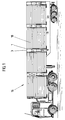
- eine Seitenansicht eines Lkw's mit einer Bordwand mit Bordwandabschlußprofilen und Bordwand-Befestigungsrungen;
- Fig. 2
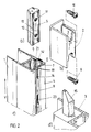
- in perspektivischer und teilweise explosionsartiger Darstellung die zugehörigen Elemente des Profils und der Runge, nämlich
- Fig. 2 a
- das Halterungsteil;
- Fig. 2 b
- den Gegenhalter mit Halterungsschrauben;
- Fig. 2 c
- einen Abschnitt des Bordwandabschlußpro fils;
- Fig. 2 d
- einen Abschnitt der Befestigungsrunge;
- Fig. 3
- eine teilweise Darstellung des Bordwandabschlußprofils und der Befestigungsrunge in Zusammenwirkungsposition, bei zurückgezogenem Verschlußriegel;
- Fig. 4
- eine Darstellung gemäß Figur 3 bei ausgefahrenem Verschlußriegel;
- Fig. 5 a, b
- einen Querschnitt durch eine Verbindung Bordwandabschlußprofil/Befestigungsrunge mit einem Halterungsteil in zwei unterschiedlichen Einbaustellungen; und
- Fig. 6
- eine Querschnittsdarstellung gemäß Figur 5 a bzw. 5 b, mit einem weiteren Bordwandabschlußprofil als Rückwand-Eckprofil.
- Dargestellt und beschrieben ist - zunächst mit Bezug zu Figur 2 - ein Bordwandabschlußprofil 1 mit einem Gegenhalter 2, zur Zusammenwirkung mit einer Bordwand-Verriegelungsrunge 3. Der Gegenhalter 2 sitzt im montierten Zustand auf dem Profil 1 von außen, auf der Profil-Stirnfläche 4, auf und ist mit einem Halterungsteil 5, das im Einbauzustand im Inneren des Profils 1, nämlich der Profilausnehmung 6, angeordnet ist, verbunden. An dem Profil 1, in der die Stirnfläche 4 ausbildenden Wand 7 ist eine Durchtrittsöffnung 8 ausgebildet, welche von Halterungsschrauben 9, 10 durchgriffen wird. Die Halterungsschrauben 9, 10 greifen in Halterungsausnehmungen 11, 12 in Form von Gewindebohrungen in dem Halterungsteil 5 ein. Im Einbauzustand liegt eine Anlagefläche 13 des Halterungsteiles 5 an einer Fläche 14 im Inneren 6 des Profils 1 an. In den Gegenhalter 2 ist in Verriegelungszustand ein Verschlußriegel 15 der Befestigungsrunge 3 eingefahren. Hierdurch ist das Bordwandabschlußprofil 1 mit der Befestigungsrunge 3 fest verbunden.
- Mit Bezug Figur 1 sind derartige Bordwandabschlußprofile 1 und Befestigungsrungen 3 beispielsweise bei Lkw's 16 verwendet. In die Bordwandabschlußprofile 1, deren zugewandte Öffnungsseiten 17, sind Bordwandelemente 18 eingeschoben und darin befestigt. Durch Entriegeln der Verbindung Befestigungsrunge 3/Bordwandabschlußprofil 1 können die Bordwände elementweise abgenommen oder beispielsweise heruntergeklappt werden. Mit Bezug wiederum zu Figur 2 ist die Fläche 14 im Inneren des im wesentlichen rechteckig bzw. quadratisch ausgebildeten Abschnittes des Bordwandabschlußprofiles 1 mit einer längsverlaufenden, in Richtung einer vertikalen Erstreckung V im Einbauzustand des Bordwandabschlußprofiles 1 ausgerichteten Strukturierung 19 versehen. Im einzelnen besteht die Struktuierung 19 aus längsverlaufenden Rippen, die sich über eine Ebene E der Fläche 14 nach Innen erheben. Die Struktierung 19 bzw. die Rippen 20, 20 a, 20 b usw. können grundsätzlich auch in die Wand 7 eingelassen sein, so daß sie sich von der Ebene E ausgehend nach Außen erstrecken. Der im wesentlichen rechteckige bzw. quadratische Abschnitt des Bordwandabschlußprofiles 1, in welchem der Gegenhalter 2 mittels des Halterungsteiles 5 befestigt ist, besitzt auch an einer zu der Wand 7 rechtwinklig (im Querschnitt) verlaufenden Wand 21 eine Strukturierung 19, in gleicher Weise wie zuvor in Bezug auf die Wand 7 beschrieben. In dieser Wand 21 ist bevorzugt eine Scheuerleiste 22 aus Polyamid angebracht. Da in der Wand 21 eine Durchtrittsöffnung 8 im Sinne einer durchgehenden längsverlaufenden Öffnung entsprechend der Wand 7 nicht möglich ist, sind in der Wand 21 bevorzugt Langlöcher 23 ausgebildet, die gleichfalls einen Durchtritt, beispielsweise der Halterungsschrauben 9, 10 ermöglichen.
- In Figur 3 ist ein Querschnitt durch eine Anordnung Bordwandabschlußprofil 1/Bordwandverriegelungsrunge 3 dargestellt, mit teilweise aufgebrochener Bordwand-Verriegelungsrunge 3 und teilweise aufgeschnittenem Gegenhalter 2. Es ist zu erkennen, daß der Verschlußriegel 15 sich in einer zurückgezogenen Stellung befindet, das Bordwandabschlußprofil 1 ist noch nicht mit der Bordwand-Verriegelungsrunge 3 verriegelt. Der Gegenhalter 2 ist mittels der Schrauben 9, 10, die als Imbusschrauben ausgeführt sind, mit dem im Inneren 6 des im wesentlichen geschlossenen, quadratischen bzw. rechteckigen Abschnitts des Bordwandabschlußprofiles 1 befindlichen Halterungsteil 5 verschraubt. Aufgrund der Strukturierung 19, nämlich der an dem Halterungsteil 5 und der Fläche 14 des Bordwandabschlußprofiles 1 ausgebildeten Rippen 20, 20 a, 20 b usw, die ineinandergreifen, ist die Verbindung Halterungsteil/Gegenhalter in Tiefen- bzw. Breitenrichtung H gesichert.
- Figur 4 zeigt eine Figur 3 entsprechende Darstellung bei in den Gegenhalter 2 eingefahrenem Verschlußriegel 15.
- Insbesondere den Figuren 5 a und 5 b ist zu entnehmen, daß die Halterungsausnehmungen, beim Ausführungsbeispiel die beiden Halterungsausnehmungen 11 und 12, bezüglich einer Mitte M des Halterungsteiles 5 außermittig angeordnet sind. Dies ermöglicht es, die Durchtrittsöffnung 8 mit einer relativ großen Breite B auszubilden. Obgleich hierbei einseitig nur ein relativ schmaler Abschnitt a der Fläche 14 bzw. der Wand 7 verbleibt, der strukturiert werden kann, d. h. mit Rippen 20, 20 a, 20 b usw. versehen werden kann, kann gleichwohl die gesamte Breite B der Durchtrittsöffnung 8 für eine Verschiebung des Gegenhalters 2 ausgenutzt werden, ohne daß eine Überdeckung ü Halterungsteil 5/ Wand 7 bzw. Fläche 14 zu klein wird. Ausgehend etwa von einer Situation gemäß Figur 5 a, in welcher sich die Halterungsschraube 10 nahe der (in der Zeichnung) unteren Seitenwand 8′ der Durchtrittsöffnung 8 befindet, kann unter Umdrehung des Halterungsteiles 5 die Halterungsschraube 10 bis nahe an die Seitenwand 8˝ der Durchtrittsöffnung 8 versetzt werden.
- Figur 6 zeigt eine Darstellung, bei welcher das Bordwandabschlußprofil 1 als Rückwand-Eckprofil eingesetzt ist. Hierbei ist eine Halterungsschraube 9 bzw. 10 durch ein Langloch 23 geführt, bei entnommener Scheuerleiste 22. Die Durchtrittsöffnung 8 bleibt ungenutzt oder kann etwa mit einem Verblendstück verschlossen werden.
- Die in der vorstehenden Beschreibung, den Ansprüchen und der Zeichnung offenbarten Merkmale der Erfindung können sowohl einzeln als auch in beliebiger Kombination für die Verwirklichung der Erfindung von Bedeutung sein.
Claims (8)
- Bordwandabschlußprofil (1), vorzugsweise für einen Lkw, mit einem Gegenhalter (2), zur Zusammenwirkung insbesondere mit einer Bordwand-Verriegelungsrunge (3), wobei der Gegenhalter (2) auf dem Profil (1) von außen aufsitzt und mit einem in dem Profil (1) angeordneten Halterungsteil (5) zur Befestigung an dem Profil (1) unter Ein- bzw. Durchgriff durch eine Durchtrittsöffnung (8, 23) in dem Profil (1) und Anlage des Halterungsteils (5) an einer Innenfläche (14) des Profils (1) verbunden ist, welche Durchtrittsöffnung (8, 23) eine Versetzung der Verbindung Gegenhalter (2)/Halterungsteil (5) (in gelockertem Zustand) in einer Richtung (höhenmäßig) zuläßt, dadurch gekennzeichnet, daß eine der zugewandten Anlageflächen (13, 14) des Halterungsteils (5) und/oder des Profils (1) für eine formschlüssige Halterung strukturiert sind und daß die Durchtrittsöffnung (8, 23) einer Versetzung der Verbindung Gegenhalter (2) /Halterungsteil (5) in zwei Richtungen zuläßt.
- Bordwandabschlußprofil (1) nach Anspruch 1, dadurch gekennzeichnet, daß die Strukturierung (19) in Längsrichtung des Profils (1), d. h. im Einbauzustand in Höhenrichtung (V) ausgerichtet ist.
- Bordwandabschlußprofil (1) nach einem oder mehreren der vorhergehenden Ansprüche, dadurch gekennzeichnet, daß die Strukturierung (19) durch längsverlaufende Rippen (20, 20 a, 20 b) gebildet ist.
- Bordwandabschlußprofil (1) nach einem oder mehreren der vorhergehenden Ansprüche, dadurch gekennzeichnet, daß die Strukturierung (19) an zwei um ca. 90° zueinander versetzten Innenflächen (14, 14′) des Profils (1) ausgebildet ist.
- Bordwandabschlußprofil (1) nach einem oder mehreren der vorhergehenden Ansprüche, wobei das Halterungsteil (5) Halterungsausnehmungen (11, 12) aufweist, dadurch gekennzeichnet, daß die Halterungsausnehmungen (11, 12) bezüglich einer Quererstreckung des Halterungsteils (5) außermittig angeordnet sind.
- Bordwandabschlußprofil (1) nach einem oder mehreren der vorhergehenden Ansprüche, dadurch gekennzeichnet, daß die Strukturierung (19) der AnlageInnenfläche (14) des Profils (1) beidseitig der Durchtrittsöffnung (8, 23) ausgebildet ist.
- Bordwandabschlußprofil (1) nach einem oder mehreren der vorhergehenden Ansprüche, dadurch gekennzeichnet, daß die Strukturierung (19) an der Anlagefläche (13) des Halterungsteils (5) beidseitig der Halterungsausnehmungen (11, 12) ausgebildet ist.
- Bordwandabschlußprofil (1) nach einem oder mehreren der vorhergehenden Ansprüche, dadurch gekennzeichnet, daß bei Ausbildung der Strukturierung (19) an zwei um 90° zueinander versetzten Innenflächen (14, 14′) die Durchtrittsöffnung (8, 23) zumindest in einer diesbezüglichen Wand (7, 21) des Profils als Langloch (23) ausgebildet ist.
Applications Claiming Priority (2)
| Application Number | Priority Date | Filing Date | Title |
|---|---|---|---|
| DE3937248 | 1989-11-09 | ||
| DE3937248A DE3937248C2 (de) | 1989-11-09 | 1989-11-09 | Bordwandabschlußprofil |
Publications (2)
| Publication Number | Publication Date |
|---|---|
| EP0427019A1 EP0427019A1 (de) | 1991-05-15 |
| EP0427019B1 true EP0427019B1 (de) | 1994-06-29 |
Family
ID=6393151
Family Applications (1)
| Application Number | Title | Priority Date | Filing Date |
|---|---|---|---|
| EP90119901A Expired - Lifetime EP0427019B1 (de) | 1989-11-09 | 1990-10-17 | Bordwandabschlussprofil |
Country Status (3)
| Country | Link |
|---|---|
| EP (1) | EP0427019B1 (de) |
| AT (1) | ATE107901T1 (de) |
| DE (2) | DE3937248C2 (de) |
Family Cites Families (4)
| Publication number | Priority date | Publication date | Assignee | Title |
|---|---|---|---|---|
| FR1584566A (de) * | 1968-06-26 | 1969-12-26 | ||
| DE7014750U (de) * | 1970-04-22 | 1970-07-30 | J & A Erbsloeh | Befestigungsvorrichtung |
| US4091746A (en) * | 1976-10-18 | 1978-05-30 | James Alvin Kimbrough | Article of furniture |
| DE2801973A1 (de) * | 1978-01-18 | 1979-07-19 | Aluminium Press Walzwerk | Kraftfahrzeugaufbau mit mindestens einer abklappbaren bordwand |
-
1989
- 1989-11-09 DE DE3937248A patent/DE3937248C2/de not_active Expired - Fee Related
-
1990
- 1990-10-17 DE DE59006306T patent/DE59006306D1/de not_active Expired - Fee Related
- 1990-10-17 AT AT90119901T patent/ATE107901T1/de not_active IP Right Cessation
- 1990-10-17 EP EP90119901A patent/EP0427019B1/de not_active Expired - Lifetime
Also Published As
| Publication number | Publication date |
|---|---|
| EP0427019A1 (de) | 1991-05-15 |
| ATE107901T1 (de) | 1994-07-15 |
| DE3937248C2 (de) | 2000-06-29 |
| DE3937248A1 (de) | 1991-05-16 |
| DE59006306D1 (de) | 1994-08-04 |
Similar Documents
| Publication | Publication Date | Title |
|---|---|---|
| DE19523790C2 (de) | Ausfahrbarer Überrollbügel | |
| DE9321498U1 (de) | Überrollbügeleinrichtung mit Innenführung und Außenführung | |
| DE19545069A1 (de) | Stoßstange mit Querträger in Halbschalenbauweise | |
| DE102013204547A1 (de) | Montageanordnung eines Handschuhfachs | |
| EP0723506B1 (de) | Dachreling für fahrzeuge | |
| EP2236711A2 (de) | Bordwandverschluss an einem Nutzfahrzeugaufbau | |
| DE69001664T2 (de) | Profil fuer tuer, fenster oder paneele. | |
| EP3130717A1 (de) | Pfosten-riegel-verbindung | |
| DE69804739T2 (de) | Vorrichtung zur Befestigung einer Vorderfront an einem Vorderbau eines Kraftfahrzeuges | |
| DE19752073A1 (de) | Kraftfahrzeugkarosserie mit einem Strukturquerträger | |
| EP0079068B1 (de) | Anhänger für Kraftfahrzeuge | |
| DE9415403U1 (de) | Scharnierbeschlag für ein Fenster, eine Tür o.dgl. | |
| DE3937248C2 (de) | Bordwandabschlußprofil | |
| EP1033278B1 (de) | Verfahren zur Befestigung von Sitzschienen | |
| DE68922953T2 (de) | Verriegelung mit Drehstange für Kraftfahrzeuge, Behälter o.dgl. | |
| AT394613B (de) | Verkleidung fuer einen stock, insbesondere einen tuerstock | |
| EP1863990B1 (de) | Treibstangenantrieb | |
| DE102007012118B4 (de) | Einstellpuffer für Kraftfahrzeuge | |
| EP0291973B1 (de) | Verbindungsstück für zwei winklig aneinanderstossende Profilstäbe von Fenster oder Türrahmen | |
| DE4114930C2 (de) | Verkleidung | |
| DE8621340U1 (de) | Vorrichtung zur Befestigung von Abdeckleisten auf Kraftwagendächern | |
| EP0584084B1 (de) | Leichtmetall-gussteil und verfahren zu seiner herstellung | |
| DE69713221T2 (de) | Personenkraftwagentürschloss | |
| EP2103466A1 (de) | Tür für einen Kofferaufbau eines Nutzfahrzeugs | |
| EP0073285B1 (de) | Verschlussvorrichtung für klappbare Bordwände eines Transportmittels, insbesondere eines Lastzuges |
Legal Events
| Date | Code | Title | Description |
|---|---|---|---|
| PUAI | Public reference made under article 153(3) epc to a published international application that has entered the european phase |
Free format text: ORIGINAL CODE: 0009012 |
|
| AK | Designated contracting states |
Kind code of ref document: A1 Designated state(s): AT BE CH DE DK ES FR GB GR IT LI LU NL SE |
|
| 17P | Request for examination filed |
Effective date: 19911107 |
|
| 17Q | First examination report despatched |
Effective date: 19930426 |
|
| RAP1 | Party data changed (applicant data changed or rights of an application transferred) |
Owner name: PWP S.A. |
|
| GRAA | (expected) grant |
Free format text: ORIGINAL CODE: 0009210 |
|
| AK | Designated contracting states |
Kind code of ref document: B1 Designated state(s): AT BE CH DE DK ES FR GB GR IT LI LU NL SE |
|
| PG25 | Lapsed in a contracting state [announced via postgrant information from national office to epo] |
Ref country code: IT Free format text: LAPSE BECAUSE OF FAILURE TO SUBMIT A TRANSLATION OF THE DESCRIPTION OR TO PAY THE FEE WITHIN THE PRE;WARNING: LAPSES OF ITALIAN PATENTS WITH EFFECTIVE DATE BEFORE 2007 MAY HAVE OCCURRED AT ANY TIME BEFORE 2007. THE CORRECT EFFECTIVE DATE MAY BE DIFFERENT FROM THE ONE RECORDED.SCRIBED TIME-LIMIT Effective date: 19940629 Ref country code: FR Effective date: 19940629 Ref country code: GR Free format text: LAPSE BECAUSE OF FAILURE TO SUBMIT A TRANSLATION OF THE DESCRIPTION OR TO PAY THE FEE WITHIN THE PRESCRIBED TIME-LIMIT Effective date: 19940629 Ref country code: BE Effective date: 19940629 Ref country code: NL Effective date: 19940629 Ref country code: DK Effective date: 19940629 Ref country code: ES Free format text: THE PATENT HAS BEEN ANNULLED BY A DECISION OF A NATIONAL AUTHORITY Effective date: 19940629 Ref country code: GB Effective date: 19940629 |
|
| REF | Corresponds to: |
Ref document number: 107901 Country of ref document: AT Date of ref document: 19940715 Kind code of ref document: T |
|
| REF | Corresponds to: |
Ref document number: 59006306 Country of ref document: DE Date of ref document: 19940804 |
|
| PG25 | Lapsed in a contracting state [announced via postgrant information from national office to epo] |
Ref country code: SE Effective date: 19940929 |
|
| PG25 | Lapsed in a contracting state [announced via postgrant information from national office to epo] |
Ref country code: LU Free format text: LAPSE BECAUSE OF NON-PAYMENT OF DUE FEES Effective date: 19941031 |
|
| EN | Fr: translation not filed | ||
| NLV1 | Nl: lapsed or annulled due to failure to fulfill the requirements of art. 29p and 29m of the patents act | ||
| GBV | Gb: ep patent (uk) treated as always having been void in accordance with gb section 77(7)/1977 [no translation filed] |
Effective date: 19940629 |
|
| PLBE | No opposition filed within time limit |
Free format text: ORIGINAL CODE: 0009261 |
|
| STAA | Information on the status of an ep patent application or granted ep patent |
Free format text: STATUS: NO OPPOSITION FILED WITHIN TIME LIMIT |
|
| 26N | No opposition filed | ||
| PGFP | Annual fee paid to national office [announced via postgrant information from national office to epo] |
Ref country code: CH Payment date: 20051010 Year of fee payment: 16 Ref country code: DE Payment date: 20051010 Year of fee payment: 16 |
|
| PGFP | Annual fee paid to national office [announced via postgrant information from national office to epo] |
Ref country code: AT Payment date: 20051013 Year of fee payment: 16 |
|
| PG25 | Lapsed in a contracting state [announced via postgrant information from national office to epo] |
Ref country code: AT Free format text: LAPSE BECAUSE OF NON-PAYMENT OF DUE FEES Effective date: 20061017 |
|
| PG25 | Lapsed in a contracting state [announced via postgrant information from national office to epo] |
Ref country code: LI Free format text: LAPSE BECAUSE OF NON-PAYMENT OF DUE FEES Effective date: 20061031 Ref country code: CH Free format text: LAPSE BECAUSE OF NON-PAYMENT OF DUE FEES Effective date: 20061031 |
|
| PG25 | Lapsed in a contracting state [announced via postgrant information from national office to epo] |
Ref country code: DE Free format text: LAPSE BECAUSE OF NON-PAYMENT OF DUE FEES Effective date: 20070501 |
|
| REG | Reference to a national code |
Ref country code: CH Ref legal event code: PL |