EP0427089B1 - Laborgerät zum Abscheiden von Stoffen aus Gasproben - Google Patents
Laborgerät zum Abscheiden von Stoffen aus Gasproben Download PDFInfo
- Publication number
- EP0427089B1 EP0427089B1 EP90120769A EP90120769A EP0427089B1 EP 0427089 B1 EP0427089 B1 EP 0427089B1 EP 90120769 A EP90120769 A EP 90120769A EP 90120769 A EP90120769 A EP 90120769A EP 0427089 B1 EP0427089 B1 EP 0427089B1
- Authority
- EP
- European Patent Office
- Prior art keywords
- nozzles
- laboratory apparatus
- charaterized
- bell
- cylinder
- Prior art date
- Legal status (The legal status is an assumption and is not a legal conclusion. Google has not performed a legal analysis and makes no representation as to the accuracy of the status listed.)
- Expired - Lifetime
Links
- 239000000126 substance Substances 0.000 title claims description 9
- 238000000926 separation method Methods 0.000 title 1
- 239000007787 solid Substances 0.000 claims description 6
- 230000000284 resting effect Effects 0.000 claims 1
- 239000007789 gas Substances 0.000 description 28
- 239000011521 glass Substances 0.000 description 22
- 239000007788 liquid Substances 0.000 description 16
- 238000010521 absorption reaction Methods 0.000 description 10
- 238000005070 sampling Methods 0.000 description 7
- 238000001179 sorption measurement Methods 0.000 description 5
- 239000000443 aerosol Substances 0.000 description 4
- 238000001514 detection method Methods 0.000 description 4
- OKTJSMMVPCPJKN-UHFFFAOYSA-N Carbon Chemical compound [C] OKTJSMMVPCPJKN-UHFFFAOYSA-N 0.000 description 2
- 229920005830 Polyurethane Foam Polymers 0.000 description 2
- 239000000463 material Substances 0.000 description 2
- 239000000203 mixture Substances 0.000 description 2
- 239000011496 polyurethane foam Substances 0.000 description 2
- 238000005406 washing Methods 0.000 description 2
- VYPSYNLAJGMNEJ-UHFFFAOYSA-N Silicium dioxide Chemical compound O=[Si]=O VYPSYNLAJGMNEJ-UHFFFAOYSA-N 0.000 description 1
- 208000007536 Thrombosis Diseases 0.000 description 1
- 239000002250 absorbent Substances 0.000 description 1
- 230000002745 absorbent Effects 0.000 description 1
- 239000006096 absorbing agent Substances 0.000 description 1
- 239000003463 adsorbent Substances 0.000 description 1
- 238000004458 analytical method Methods 0.000 description 1
- 239000000919 ceramic Substances 0.000 description 1
- 239000000428 dust Substances 0.000 description 1
- 230000000694 effects Effects 0.000 description 1
- 230000007613 environmental effect Effects 0.000 description 1
- 238000000605 extraction Methods 0.000 description 1
- 239000010419 fine particle Substances 0.000 description 1
- 239000006260 foam Substances 0.000 description 1
- 229930195733 hydrocarbon Natural products 0.000 description 1
- 230000001771 impaired effect Effects 0.000 description 1
- 238000005259 measurement Methods 0.000 description 1
- 239000002184 metal Substances 0.000 description 1
- 239000003595 mist Substances 0.000 description 1
- 239000002245 particle Substances 0.000 description 1
- -1 polycyclic hydrocarbons Chemical class 0.000 description 1
- 239000002952 polymeric resin Substances 0.000 description 1
- 229920002635 polyurethane Polymers 0.000 description 1
- 239000004814 polyurethane Substances 0.000 description 1
- 238000011002 quantification Methods 0.000 description 1
- 230000000717 retained effect Effects 0.000 description 1
- 239000000741 silica gel Substances 0.000 description 1
- 229910002027 silica gel Inorganic materials 0.000 description 1
- 239000007921 spray Substances 0.000 description 1
- 230000003068 static effect Effects 0.000 description 1
- 229920003002 synthetic resin Polymers 0.000 description 1
- 238000004454 trace mineral analysis Methods 0.000 description 1
Images

Classifications
-
- G—PHYSICS
- G01—MEASURING; TESTING
- G01N—INVESTIGATING OR ANALYSING MATERIALS BY DETERMINING THEIR CHEMICAL OR PHYSICAL PROPERTIES
- G01N1/00—Sampling; Preparing specimens for investigation
- G01N1/02—Devices for withdrawing samples
- G01N1/22—Devices for withdrawing samples in the gaseous state
- G01N1/2202—Devices for withdrawing samples in the gaseous state involving separation of sample components during sampling
- G01N1/2214—Devices for withdrawing samples in the gaseous state involving separation of sample components during sampling by sorption
-
- B—PERFORMING OPERATIONS; TRANSPORTING
- B01—PHYSICAL OR CHEMICAL PROCESSES OR APPARATUS IN GENERAL
- B01L—CHEMICAL OR PHYSICAL LABORATORY APPARATUS FOR GENERAL USE
- B01L5/00—Gas handling apparatus
- B01L5/04—Gas washing apparatus, e.g. by bubbling
-
- G—PHYSICS
- G01—MEASURING; TESTING
- G01N—INVESTIGATING OR ANALYSING MATERIALS BY DETERMINING THEIR CHEMICAL OR PHYSICAL PROPERTIES
- G01N1/00—Sampling; Preparing specimens for investigation
- G01N1/02—Devices for withdrawing samples
- G01N1/22—Devices for withdrawing samples in the gaseous state
- G01N1/2202—Devices for withdrawing samples in the gaseous state involving separation of sample components during sampling
- G01N1/2214—Devices for withdrawing samples in the gaseous state involving separation of sample components during sampling by sorption
- G01N2001/2217—Devices for withdrawing samples in the gaseous state involving separation of sample components during sampling by sorption using a liquid
-
- G—PHYSICS
- G01—MEASURING; TESTING
- G01N—INVESTIGATING OR ANALYSING MATERIALS BY DETERMINING THEIR CHEMICAL OR PHYSICAL PROPERTIES
- G01N1/00—Sampling; Preparing specimens for investigation
- G01N1/02—Devices for withdrawing samples
- G01N1/22—Devices for withdrawing samples in the gaseous state
- G01N1/2202—Devices for withdrawing samples in the gaseous state involving separation of sample components during sampling
- G01N2001/222—Other features
- G01N2001/2223—Other features aerosol sampling devices
-
- G—PHYSICS
- G01—MEASURING; TESTING
- G01N—INVESTIGATING OR ANALYSING MATERIALS BY DETERMINING THEIR CHEMICAL OR PHYSICAL PROPERTIES
- G01N1/00—Sampling; Preparing specimens for investigation
- G01N1/28—Preparing specimens for investigation including physical details of (bio-)chemical methods covered elsewhere, e.g. G01N33/50, C12Q
- G01N1/40—Concentrating samples
- G01N1/4055—Concentrating samples by solubility techniques
- G01N2001/4066—Concentrating samples by solubility techniques using difference of solubility between liquid and gas, e.g. bubbling, scrubbing or sparging
Definitions
- the invention relates to a laboratory device for separating gaseous, liquid and solid substances from gas samples, consisting of a cylindrical vessel with a sleeve and an impact surface and a mixing insert, which has a core which can be inserted into the sleeve, an inlet tube guided through the core and an outlet tube having.
- gaseous, liquid, droplet and solid particles so-called aerosols and dusts, from gases, primarily from air
- a liquid absorbent absorption
- adsorption surface-rich solid
- Different types of wash bottles adsorbents such as activated carbon, silica gel, polymer resins and polyurethane foam are known for this purpose.
- absorbers which work with washing liquids are laboratory devices referred to as impingers in laboratory technology with a mixed insert.
- the gas stream to be examined is introduced into the washing liquid through an appropriately designed nozzle in such a way that an ultrasound-like mixing occurs as a result of an intensive impact of the gas stream on the liquid surface. It is thereby achieved that the mixing takes place intensively and with very fine particles.
- the foam or gas / liquid mixture formed is back-mixed with the main amount of the absorption liquid by the vortices generated with the aid of the feed nozzle. The discharge of the liquid is thus kept very small.
- such devices are also very well suited for the adsorption of dusts, in particular very fine dusts.
- the effective working range of the gas throughput is between approx. 0.5 m3 / h and 1.5 m3 / h.
- the upper limit for the throughput of such an arrangement is reached, especially when two devices are connected in series.
- the optimal throughput range is between approx. 1.0 and 1.5 m3 / h.
- the wider gas jet displaces the absorption liquid on the baffle plate, so that there is no real mixing, but only an impact of the gas stream with subsequent side mixing, which more or less corresponds to a wash bottle characteristic. If the nozzles are too large and the throughput is too high, the pressure on the apparatus parts becomes so great that the stability of the devices and the safety are impaired in the case of glass vessels, which are necessary above all for analytical determination.
- the task was to develop a laboratory device for separating gaseous, liquid and solid substances from gas samples, which allows a significantly higher gas throughput than the known devices, so that for low substance concentrations to be measured in a short time Sampling time enough gas can be collected.
- the new laboratory device should be easy to handle and easy to rinse with a view to complete detection of the trace substances.
- the object was achieved by a laboratory device of the type described in the introduction, in which, according to the invention, a plurality of nozzles are provided which are connected to the lower end of the inlet pipe via a distribution device.
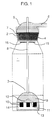
- the laboratory device made of glass (example below) or another inert material, such as metal or ceramic, consists of two parts: a cylindrical glass vessel 1 with a ground sleeve 2 at the vessel opening and a mixing insert 3 with a ground core 4 that can be inserted into the ground sleeve Ground joint is a collecting bell 5 with a side outlet tube 6, which is connected via openings 7 in the ground core to the interior of the glass vessel.
- an inlet pipe 8 is guided through the collecting bell 5 and the ground core 4, which opens out in the lower part of the glass vessel 1 centrally into a hemispherical, closed glass bell 9 (FIG. 1).
- the glass bell serves as a distribution device for nozzles 10 which are evenly distributed in a circle and have a nozzle bore between 2 and 3 mm, which are melted into the bell bottom 11. It is advantageous to provide a guide surface 12 above the bell bottom, for example in the form of an all-round concave cone, in order to promote the drainage of the absorption liquid when the device is rinsed.
- the nozzles 10 end approximately 4 mm above a baffle plate 13 which is fused to the glass bell 9 by means of glass webs 14.
- the nozzles 10 can also be arranged on the circumference of the glass bell 9, so that they are directed onto an impact surface arranged on the inner circumference of the vessel 1.
- the mixed insert is rinsed after removal from the glass vessel in order to obtain foreign matter deposits and the analytical material consisting of it and the contents of the vessel are sent for an analytical determination.
- the distribution device for the sucked gas consists of a closed glass cylinder 17 which is rotatably supported on the bottom of the vessel by means of a bearing cone 19 attached to the cylinder base 18.
- the rotary connection between the fixed inlet pipe 8 and the rotatable cylinder is produced by a tubular grinding core 20 melted onto the inlet pipe and a ground sleeve 21 integrated into the glass cylinder.
- the ground sleeve is provided with at least two opposite openings 22 through which the gas to be examined can flow from the inlet pipe 8 into the glass cylinder 17.
- the nozzles 10 are melted into the cylinder wall, which are directed towards the vessel wall and end approximately 4 mm in front of it.
- the glass cylinder is set in rotation due to the escaping gas jets due to the slight inclination of the nozzles in the same direction to the cylinder radius. This also creates a certain spin and thrombus effect, which intensifies the mixing of gas and absorption liquid.
- the nozzles 10 can also be attached to the cylinder base instead of to the cylinder wall. It is also possible to make the glass bell 9 described above rotatable in the same way.
- a hold-down device for the glass cylinder 17 for example in the form of a glass pin 23 which is melted in the inlet pipe 8 and which extends close to the bottom of the ground sleeve 21, which prevents the cylinder from being pushed upwards by buoyant forces and thereby the bottom of the ground sleeve comes into frictional contact with the ground core 20.
- the laboratory device according to the invention allows, due to the multiple nozzle arrangement with a variable number of nozzles, in comparison to the known devices, the sampling of considerably larger amounts of gas in a comparable period of time or, with the gas amounts previously used, a significantly shorter sampling time. This significantly expands the use of trace analysis.
Landscapes
- Health & Medical Sciences (AREA)
- Life Sciences & Earth Sciences (AREA)
- Chemical & Material Sciences (AREA)
- Physics & Mathematics (AREA)
- Biochemistry (AREA)
- Engineering & Computer Science (AREA)
- Biomedical Technology (AREA)
- Molecular Biology (AREA)
- Clinical Laboratory Science (AREA)
- Analytical Chemistry (AREA)
- Chemical Kinetics & Catalysis (AREA)
- General Health & Medical Sciences (AREA)
- General Physics & Mathematics (AREA)
- Immunology (AREA)
- Pathology (AREA)
- Sampling And Sample Adjustment (AREA)
- Devices For Use In Laboratory Experiments (AREA)
Applications Claiming Priority (2)
| Application Number | Priority Date | Filing Date | Title |
|---|---|---|---|
| DE3937134A DE3937134A1 (de) | 1989-11-08 | 1989-11-08 | Laborgeraet zum abscheiden von stoffen aus gasproben |
| DE3937134 | 1989-11-08 |
Publications (3)
| Publication Number | Publication Date |
|---|---|
| EP0427089A2 EP0427089A2 (de) | 1991-05-15 |
| EP0427089A3 EP0427089A3 (en) | 1991-12-11 |
| EP0427089B1 true EP0427089B1 (de) | 1994-12-28 |
Family
ID=6393087
Family Applications (1)
| Application Number | Title | Priority Date | Filing Date |
|---|---|---|---|
| EP90120769A Expired - Lifetime EP0427089B1 (de) | 1989-11-08 | 1990-10-30 | Laborgerät zum Abscheiden von Stoffen aus Gasproben |
Country Status (5)
| Country | Link |
|---|---|
| US (1) | US5154891A (da) |
| EP (1) | EP0427089B1 (da) |
| JP (1) | JPH03174250A (da) |
| DE (2) | DE3937134A1 (da) |
| DK (1) | DK0427089T3 (da) |
Families Citing this family (16)
| Publication number | Priority date | Publication date | Assignee | Title |
|---|---|---|---|---|
| USD399972S (en) | 1996-05-28 | 1998-10-20 | Foscato John O | Top for an impinger |
| DE19643427C1 (de) * | 1996-10-22 | 1998-02-12 | Bundesrep Deutschland | Verfahren zur Bestimmung von Allergenen in der Luft |
| FR2773217B1 (fr) * | 1997-12-30 | 2001-06-08 | Controles Lab Et | Utilisation d'une interaction entre un gaz et un liquide pour le prelevement des elements gazeux et particulaires d'un milieu gazeux en vue de leur analyse |
| US6306658B1 (en) | 1998-08-13 | 2001-10-23 | Symyx Technologies | Parallel reactor with internal sensing |
| US6528026B2 (en) | 1998-08-13 | 2003-03-04 | Symyx Technologies, Inc. | Multi-temperature modular reactor and method of using same |
| US6455316B1 (en) | 1998-08-13 | 2002-09-24 | Symyx Technologies, Inc. | Parallel reactor with internal sensing and method of using same |
| US6548026B1 (en) | 1998-08-13 | 2003-04-15 | Symyx Technologies, Inc. | Parallel reactor with internal sensing and method of using same |
| US6890492B1 (en) | 1998-08-13 | 2005-05-10 | Symyx Technologies, Inc. | Parallel reactor with internal sensing and method of using same |
| US6994827B2 (en) | 2000-06-03 | 2006-02-07 | Symyx Technologies, Inc. | Parallel semicontinuous or continuous reactors |
| GB0024227D0 (en) | 2000-10-04 | 2000-11-15 | Secr Defence | Air samplers |
| EP1199099A1 (en) * | 2000-10-19 | 2002-04-24 | Amersham Biosciences AB | Reactor |
| US6582116B2 (en) | 2001-09-24 | 2003-06-24 | Symyx Technologies, Inc. | Apparatus and method for mixing small volumes of reaction materials |
| US7699915B2 (en) * | 2006-08-24 | 2010-04-20 | Microfluidic Systems, Inc. | Liquid impingement unit |
| CN108362828B (zh) * | 2014-11-21 | 2020-02-18 | 中国环境科学研究院 | 一种用于采集大气中过氧化物的雾液吸收装置 |
| CN105807009B (zh) * | 2016-05-06 | 2017-07-07 | 中科同德(北京)生态科技有限公司 | 一种室内空气环境监测设备的进风结构 |
| EP3461553A1 (de) * | 2017-09-28 | 2019-04-03 | Dr.-Ing. Ritter Apparatebau GmbH & Co.KG | Co2-absorptionsflasche |
Family Cites Families (10)
| Publication number | Priority date | Publication date | Assignee | Title |
|---|---|---|---|---|
| US2552260A (en) * | 1951-05-08 | Apparatus for the manufacture of | ||
| GB239761A (en) * | 1924-12-22 | 1925-09-17 | Collin & Company | Improvements in or relating to washing or absorption apparatus for gases or vapours |
| US1887126A (en) * | 1929-06-08 | 1932-11-08 | Firm Of Jenaer Glaswerk Schott | Distributor for extraction apparatus |
| US2254352A (en) * | 1937-12-08 | 1941-09-02 | Standard Oil Dev Co | Process for the manufacture of alkyl nitrates |
| GB541093A (en) * | 1940-04-11 | 1941-11-14 | Brush Electrical Eng | New or improved means for purifying and/or cleansing gases |
| US2687948A (en) * | 1949-02-11 | 1954-08-31 | Gregory Paul | Methods of and means for thermal operations |
| BE505351A (da) * | 1950-08-23 | |||
| NL167579B (nl) * | 1952-02-20 | Union Carbide Corp | Werkwijze voor het aan een einde afsluiten van een holle "stick", bestemd om als omhulsel bij het maken van worst en dergelijke te dienen. | |
| IT951874B (it) * | 1972-04-27 | 1973-07-10 | Robbiati C | Dispositivo depuratore di fumo e gas di scarico per autoveicoli in genere |
| US4737168A (en) * | 1987-07-22 | 1988-04-12 | U.S. Enertek, Inc. | Solids separation system for natural gas wells |
-
1989
- 1989-11-08 DE DE3937134A patent/DE3937134A1/de not_active Withdrawn
-
1990
- 1990-10-30 EP EP90120769A patent/EP0427089B1/de not_active Expired - Lifetime
- 1990-10-30 DK DK90120769.6T patent/DK0427089T3/da active
- 1990-10-30 DE DE59008136T patent/DE59008136D1/de not_active Expired - Lifetime
- 1990-10-31 US US07/606,323 patent/US5154891A/en not_active Expired - Fee Related
- 1990-11-07 JP JP2300013A patent/JPH03174250A/ja active Pending
Also Published As
| Publication number | Publication date |
|---|---|
| US5154891A (en) | 1992-10-13 |
| DE59008136D1 (de) | 1995-02-09 |
| DE3937134A1 (de) | 1991-05-16 |
| EP0427089A3 (en) | 1991-12-11 |
| DK0427089T3 (da) | 1995-02-27 |
| JPH03174250A (ja) | 1991-07-29 |
| EP0427089A2 (de) | 1991-05-15 |
Similar Documents
| Publication | Publication Date | Title |
|---|---|---|
| EP0427089B1 (de) | Laborgerät zum Abscheiden von Stoffen aus Gasproben | |
| DE69126075T2 (de) | Gasgespülter Hydrozyklon | |
| DE2134808C3 (da) | ||
| DE69224285T2 (de) | Verfahren zum reinigen pipetten in einem fluessigkeitanalyseapparat | |
| DE1619899B2 (de) | Vorrichtung zum entgasen von fluessigkeiten | |
| DE2016032A1 (da) | ||
| DE2949411A1 (de) | Verfahren und vorrichtung zum entgasen und analysieren schaeumender fluessigkeiten | |
| DE69014891T2 (de) | Vorrichtung zum herstellen einer partikeldispersion. | |
| DE69617808T2 (de) | Wäscher für Gas- und Dampfströme aus Industrieprozessen | |
| DE4216961A1 (de) | Vorrichtung zum Trennen von Öl und Wasser | |
| EP0643989B1 (de) | Verfahren und System zur Mischung von Flüssigkeiten | |
| EP0281630A1 (de) | Verwirbelungsvorrichtung für massenaustausch-trennungsapparate | |
| EP1368132B1 (de) | Beschichtungsvorrichtung für ein langgestrecktes werkstück | |
| DE2330135A1 (de) | Verfahren zur absaugung einer fluessigkeit und absaugvorrichtung zur durchfuehrung des verfahrens | |
| EP0481577B1 (de) | Vorrichtung zur kontinuierlichen Entnahme von Proben aus einem partikelbelasteten Strömungsmedium | |
| DE4005094C2 (de) | Schäumvorrichtung | |
| DE4427314A1 (de) | Vorrichtung zur Untersuchung von Behältern auf Fremdgase | |
| DE4233480C2 (de) | Gerät zum Abscheiden von Öl aus einem in einem komprimierten Gasstrom mitgeführten Öl/Wasser-Gemisch | |
| DE2651903A1 (de) | Verfahren und vorrichtung zur vorbereitung analytischer probereihen und zur ueberfuehrung dieser reihen von einer linearen in eine radiale anordnung | |
| DE3026923C2 (de) | Vorrichtung zum Behandeln von Filtermaterial | |
| DE3818991C1 (en) | Process and apparatus for mixing two fluids | |
| DE10024124C1 (de) | Vorrichtung zur Trennung von Flüssigkeiten mit unterschiedlichen Siedepunkten, insbesondere zur Abscheidung von Wasser aus Öl | |
| DE4115580C1 (en) | Irradiation appts. for photochemical reactions - has rotation symmetrical reaction vessel through which flowable medium can pass | |
| DE4021239C2 (de) | Verfahren und Vorrichtung zum Extrahieren gelöster flüchtiger Substanzen aus Flüssigkeiten in die Gasphase | |
| DE1244718B (de) | Vorrichtung zur Reinigung eines Staub enthaltenden Gases mittels Schaum |
Legal Events
| Date | Code | Title | Description |
|---|---|---|---|
| PUAI | Public reference made under article 153(3) epc to a published international application that has entered the european phase |
Free format text: ORIGINAL CODE: 0009012 |
|
| 17P | Request for examination filed |
Effective date: 19901227 |
|
| AK | Designated contracting states |
Kind code of ref document: A2 Designated state(s): CH DE DK FR GB IT LI NL SE |
|
| PUAL | Search report despatched |
Free format text: ORIGINAL CODE: 0009013 |
|
| AK | Designated contracting states |
Kind code of ref document: A3 Designated state(s): CH DE DK FR GB IT LI NL SE |
|
| 17Q | First examination report despatched |
Effective date: 19930311 |
|
| GRAA | (expected) grant |
Free format text: ORIGINAL CODE: 0009210 |
|
| AK | Designated contracting states |
Kind code of ref document: B1 Designated state(s): CH DE DK FR GB IT LI NL SE |
|
| EAL | Se: european patent in force in sweden |
Ref document number: 90120769.6 |
|
| ITF | It: translation for a ep patent filed | ||
| REF | Corresponds to: |
Ref document number: 59008136 Country of ref document: DE Date of ref document: 19950209 |
|
| GBT | Gb: translation of ep patent filed (gb section 77(6)(a)/1977) |
Effective date: 19950116 |
|
| REG | Reference to a national code |
Ref country code: DK Ref legal event code: T3 |
|
| ET | Fr: translation filed | ||
| PLBE | No opposition filed within time limit |
Free format text: ORIGINAL CODE: 0009261 |
|
| STAA | Information on the status of an ep patent application or granted ep patent |
Free format text: STATUS: NO OPPOSITION FILED WITHIN TIME LIMIT |
|
| 26N | No opposition filed | ||
| PGFP | Annual fee paid to national office [announced via postgrant information from national office to epo] |
Ref country code: FR Payment date: 20010914 Year of fee payment: 12 |
|
| PGFP | Annual fee paid to national office [announced via postgrant information from national office to epo] |
Ref country code: SE Payment date: 20010917 Year of fee payment: 12 Ref country code: CH Payment date: 20010917 Year of fee payment: 12 |
|
| PGFP | Annual fee paid to national office [announced via postgrant information from national office to epo] |
Ref country code: NL Payment date: 20010921 Year of fee payment: 12 Ref country code: DK Payment date: 20010921 Year of fee payment: 12 |
|
| PGFP | Annual fee paid to national office [announced via postgrant information from national office to epo] |
Ref country code: GB Payment date: 20011015 Year of fee payment: 12 |
|
| PGFP | Annual fee paid to national office [announced via postgrant information from national office to epo] |
Ref country code: DE Payment date: 20011018 Year of fee payment: 12 |
|
| REG | Reference to a national code |
Ref country code: GB Ref legal event code: IF02 |
|
| PG25 | Lapsed in a contracting state [announced via postgrant information from national office to epo] |
Ref country code: GB Free format text: LAPSE BECAUSE OF NON-PAYMENT OF DUE FEES Effective date: 20021030 |
|
| PG25 | Lapsed in a contracting state [announced via postgrant information from national office to epo] |
Ref country code: SE Free format text: LAPSE BECAUSE OF NON-PAYMENT OF DUE FEES Effective date: 20021031 Ref country code: LI Free format text: LAPSE BECAUSE OF NON-PAYMENT OF DUE FEES Effective date: 20021031 Ref country code: DK Free format text: LAPSE BECAUSE OF NON-PAYMENT OF DUE FEES Effective date: 20021031 Ref country code: CH Free format text: LAPSE BECAUSE OF NON-PAYMENT OF DUE FEES Effective date: 20021031 |
|
| PG25 | Lapsed in a contracting state [announced via postgrant information from national office to epo] |
Ref country code: DE Free format text: LAPSE BECAUSE OF THE APPLICANT RENOUNCES Effective date: 20021116 |
|
| PG25 | Lapsed in a contracting state [announced via postgrant information from national office to epo] |
Ref country code: NL Free format text: LAPSE BECAUSE OF NON-PAYMENT OF DUE FEES Effective date: 20030501 |
|
| EUG | Se: european patent has lapsed | ||
| REG | Reference to a national code |
Ref country code: CH Ref legal event code: PL |
|
| REG | Reference to a national code |
Ref country code: DK Ref legal event code: EBP |
|
| GBPC | Gb: european patent ceased through non-payment of renewal fee | ||
| PG25 | Lapsed in a contracting state [announced via postgrant information from national office to epo] |
Ref country code: FR Free format text: LAPSE BECAUSE OF NON-PAYMENT OF DUE FEES Effective date: 20030630 |
|
| NLV4 | Nl: lapsed or anulled due to non-payment of the annual fee |
Effective date: 20030501 |
|
| REG | Reference to a national code |
Ref country code: FR Ref legal event code: ST |
|
| PG25 | Lapsed in a contracting state [announced via postgrant information from national office to epo] |
Ref country code: IT Free format text: LAPSE BECAUSE OF NON-PAYMENT OF DUE FEES;WARNING: LAPSES OF ITALIAN PATENTS WITH EFFECTIVE DATE BEFORE 2007 MAY HAVE OCCURRED AT ANY TIME BEFORE 2007. THE CORRECT EFFECTIVE DATE MAY BE DIFFERENT FROM THE ONE RECORDED. Effective date: 20051030 |