EP0427112A1 - Procédé et dispositif de production de la phase gazeuse d'un volume de liquide stocké dans la phase liquide - Google Patents
Procédé et dispositif de production de la phase gazeuse d'un volume de liquide stocké dans la phase liquide Download PDFInfo
- Publication number
- EP0427112A1 EP0427112A1 EP19900120933 EP90120933A EP0427112A1 EP 0427112 A1 EP0427112 A1 EP 0427112A1 EP 19900120933 EP19900120933 EP 19900120933 EP 90120933 A EP90120933 A EP 90120933A EP 0427112 A1 EP0427112 A1 EP 0427112A1
- Authority
- EP
- European Patent Office
- Prior art keywords
- temperature
- circuit
- heat
- heat transfer
- phase
- Prior art date
- Legal status (The legal status is an assumption and is not a legal conclusion. Google has not performed a legal analysis and makes no representation as to the accuracy of the status listed.)
- Granted
Links
Images

Classifications
-
- F—MECHANICAL ENGINEERING; LIGHTING; HEATING; WEAPONS; BLASTING
- F17—STORING OR DISTRIBUTING GASES OR LIQUIDS
- F17C—VESSELS FOR CONTAINING OR STORING COMPRESSED, LIQUEFIED OR SOLIDIFIED GASES; FIXED-CAPACITY GAS-HOLDERS; FILLING VESSELS WITH, OR DISCHARGING FROM VESSELS, COMPRESSED, LIQUEFIED, OR SOLIDIFIED GASES
- F17C9/00—Methods or apparatus for discharging liquefied or solidified gases from vessels not under pressure
- F17C9/02—Methods or apparatus for discharging liquefied or solidified gases from vessels not under pressure with change of state, e.g. vaporisation
-
- F—MECHANICAL ENGINEERING; LIGHTING; HEATING; WEAPONS; BLASTING
- F24—HEATING; RANGES; VENTILATING
- F24F—AIR-CONDITIONING; AIR-HUMIDIFICATION; VENTILATION; USE OF AIR CURRENTS FOR SCREENING
- F24F12/00—Use of energy recovery systems in air conditioning, ventilation or screening
- F24F12/001—Use of energy recovery systems in air conditioning, ventilation or screening with heat-exchange between supplied and exhausted air
-
- F—MECHANICAL ENGINEERING; LIGHTING; HEATING; WEAPONS; BLASTING
- F25—REFRIGERATION OR COOLING; COMBINED HEATING AND REFRIGERATION SYSTEMS; HEAT PUMP SYSTEMS; MANUFACTURE OR STORAGE OF ICE; LIQUEFACTION SOLIDIFICATION OF GASES
- F25D—REFRIGERATORS; COLD ROOMS; ICE-BOXES; COOLING OR FREEZING APPARATUS NOT OTHERWISE PROVIDED FOR
- F25D17/00—Arrangements for circulating cooling fluids; Arrangements for circulating gas, e.g. air, within refrigerated spaces
- F25D17/02—Arrangements for circulating cooling fluids; Arrangements for circulating gas, e.g. air, within refrigerated spaces for circulating liquids, e.g. brine
-
- F—MECHANICAL ENGINEERING; LIGHTING; HEATING; WEAPONS; BLASTING
- F25—REFRIGERATION OR COOLING; COMBINED HEATING AND REFRIGERATION SYSTEMS; HEAT PUMP SYSTEMS; MANUFACTURE OR STORAGE OF ICE; LIQUEFACTION SOLIDIFICATION OF GASES
- F25D—REFRIGERATORS; COLD ROOMS; ICE-BOXES; COOLING OR FREEZING APPARATUS NOT OTHERWISE PROVIDED FOR
- F25D3/00—Devices using other cold materials; Devices using cold-storage bodies
- F25D3/10—Devices using other cold materials; Devices using cold-storage bodies using liquefied gases, e.g. liquid air
-
- F—MECHANICAL ENGINEERING; LIGHTING; HEATING; WEAPONS; BLASTING
- F17—STORING OR DISTRIBUTING GASES OR LIQUIDS
- F17C—VESSELS FOR CONTAINING OR STORING COMPRESSED, LIQUEFIED OR SOLIDIFIED GASES; FIXED-CAPACITY GAS-HOLDERS; FILLING VESSELS WITH, OR DISCHARGING FROM VESSELS, COMPRESSED, LIQUEFIED, OR SOLIDIFIED GASES
- F17C2201/00—Vessel construction, in particular geometry, arrangement or size
- F17C2201/01—Shape
- F17C2201/0104—Shape cylindrical
- F17C2201/0109—Shape cylindrical with exteriorly curved end-piece
-
- F—MECHANICAL ENGINEERING; LIGHTING; HEATING; WEAPONS; BLASTING
- F17—STORING OR DISTRIBUTING GASES OR LIQUIDS
- F17C—VESSELS FOR CONTAINING OR STORING COMPRESSED, LIQUEFIED OR SOLIDIFIED GASES; FIXED-CAPACITY GAS-HOLDERS; FILLING VESSELS WITH, OR DISCHARGING FROM VESSELS, COMPRESSED, LIQUEFIED, OR SOLIDIFIED GASES
- F17C2201/00—Vessel construction, in particular geometry, arrangement or size
- F17C2201/01—Shape
- F17C2201/0138—Shape tubular
-
- F—MECHANICAL ENGINEERING; LIGHTING; HEATING; WEAPONS; BLASTING
- F17—STORING OR DISTRIBUTING GASES OR LIQUIDS
- F17C—VESSELS FOR CONTAINING OR STORING COMPRESSED, LIQUEFIED OR SOLIDIFIED GASES; FIXED-CAPACITY GAS-HOLDERS; FILLING VESSELS WITH, OR DISCHARGING FROM VESSELS, COMPRESSED, LIQUEFIED, OR SOLIDIFIED GASES
- F17C2205/00—Vessel construction, in particular mounting arrangements, attachments or identifications means
- F17C2205/01—Mounting arrangements
- F17C2205/0153—Details of mounting arrangements
- F17C2205/018—Supporting feet
-
- F—MECHANICAL ENGINEERING; LIGHTING; HEATING; WEAPONS; BLASTING
- F17—STORING OR DISTRIBUTING GASES OR LIQUIDS
- F17C—VESSELS FOR CONTAINING OR STORING COMPRESSED, LIQUEFIED OR SOLIDIFIED GASES; FIXED-CAPACITY GAS-HOLDERS; FILLING VESSELS WITH, OR DISCHARGING FROM VESSELS, COMPRESSED, LIQUEFIED, OR SOLIDIFIED GASES
- F17C2205/00—Vessel construction, in particular mounting arrangements, attachments or identifications means
- F17C2205/03—Fluid connections, filters, valves, closure means or other attachments
- F17C2205/0302—Fittings, valves, filters, or components in connection with the gas storage device
- F17C2205/0323—Valves
-
- F—MECHANICAL ENGINEERING; LIGHTING; HEATING; WEAPONS; BLASTING
- F17—STORING OR DISTRIBUTING GASES OR LIQUIDS
- F17C—VESSELS FOR CONTAINING OR STORING COMPRESSED, LIQUEFIED OR SOLIDIFIED GASES; FIXED-CAPACITY GAS-HOLDERS; FILLING VESSELS WITH, OR DISCHARGING FROM VESSELS, COMPRESSED, LIQUEFIED, OR SOLIDIFIED GASES
- F17C2223/00—Handled fluid before transfer, i.e. state of fluid when stored in the vessel or before transfer from the vessel
- F17C2223/01—Handled fluid before transfer, i.e. state of fluid when stored in the vessel or before transfer from the vessel characterised by the phase
- F17C2223/0146—Two-phase
- F17C2223/0153—Liquefied gas, e.g. LPG, GPL
-
- F—MECHANICAL ENGINEERING; LIGHTING; HEATING; WEAPONS; BLASTING
- F17—STORING OR DISTRIBUTING GASES OR LIQUIDS
- F17C—VESSELS FOR CONTAINING OR STORING COMPRESSED, LIQUEFIED OR SOLIDIFIED GASES; FIXED-CAPACITY GAS-HOLDERS; FILLING VESSELS WITH, OR DISCHARGING FROM VESSELS, COMPRESSED, LIQUEFIED, OR SOLIDIFIED GASES
- F17C2225/00—Handled fluid after transfer, i.e. state of fluid after transfer from the vessel
- F17C2225/01—Handled fluid after transfer, i.e. state of fluid after transfer from the vessel characterised by the phase
- F17C2225/0107—Single phase
- F17C2225/0123—Single phase gaseous, e.g. CNG, GNC
-
- F—MECHANICAL ENGINEERING; LIGHTING; HEATING; WEAPONS; BLASTING
- F17—STORING OR DISTRIBUTING GASES OR LIQUIDS
- F17C—VESSELS FOR CONTAINING OR STORING COMPRESSED, LIQUEFIED OR SOLIDIFIED GASES; FIXED-CAPACITY GAS-HOLDERS; FILLING VESSELS WITH, OR DISCHARGING FROM VESSELS, COMPRESSED, LIQUEFIED, OR SOLIDIFIED GASES
- F17C2227/00—Transfer of fluids, i.e. method or means for transferring the fluid; Heat exchange with the fluid
- F17C2227/03—Heat exchange with the fluid
- F17C2227/0302—Heat exchange with the fluid by heating
-
- F—MECHANICAL ENGINEERING; LIGHTING; HEATING; WEAPONS; BLASTING
- F17—STORING OR DISTRIBUTING GASES OR LIQUIDS
- F17C—VESSELS FOR CONTAINING OR STORING COMPRESSED, LIQUEFIED OR SOLIDIFIED GASES; FIXED-CAPACITY GAS-HOLDERS; FILLING VESSELS WITH, OR DISCHARGING FROM VESSELS, COMPRESSED, LIQUEFIED, OR SOLIDIFIED GASES
- F17C2227/00—Transfer of fluids, i.e. method or means for transferring the fluid; Heat exchange with the fluid
- F17C2227/03—Heat exchange with the fluid
- F17C2227/0367—Localisation of heat exchange
- F17C2227/0388—Localisation of heat exchange separate
- F17C2227/0393—Localisation of heat exchange separate using a vaporiser
-
- F—MECHANICAL ENGINEERING; LIGHTING; HEATING; WEAPONS; BLASTING
- F17—STORING OR DISTRIBUTING GASES OR LIQUIDS
- F17C—VESSELS FOR CONTAINING OR STORING COMPRESSED, LIQUEFIED OR SOLIDIFIED GASES; FIXED-CAPACITY GAS-HOLDERS; FILLING VESSELS WITH, OR DISCHARGING FROM VESSELS, COMPRESSED, LIQUEFIED, OR SOLIDIFIED GASES
- F17C2250/00—Accessories; Control means; Indicating, measuring or monitoring of parameters
- F17C2250/03—Control means
- F17C2250/032—Control means using computers
-
- F—MECHANICAL ENGINEERING; LIGHTING; HEATING; WEAPONS; BLASTING
- F17—STORING OR DISTRIBUTING GASES OR LIQUIDS
- F17C—VESSELS FOR CONTAINING OR STORING COMPRESSED, LIQUEFIED OR SOLIDIFIED GASES; FIXED-CAPACITY GAS-HOLDERS; FILLING VESSELS WITH, OR DISCHARGING FROM VESSELS, COMPRESSED, LIQUEFIED, OR SOLIDIFIED GASES
- F17C2250/00—Accessories; Control means; Indicating, measuring or monitoring of parameters
- F17C2250/06—Controlling or regulating of parameters as output values
- F17C2250/0605—Parameters
- F17C2250/0631—Temperature
-
- Y—GENERAL TAGGING OF NEW TECHNOLOGICAL DEVELOPMENTS; GENERAL TAGGING OF CROSS-SECTIONAL TECHNOLOGIES SPANNING OVER SEVERAL SECTIONS OF THE IPC; TECHNICAL SUBJECTS COVERED BY FORMER USPC CROSS-REFERENCE ART COLLECTIONS [XRACs] AND DIGESTS
- Y02—TECHNOLOGIES OR APPLICATIONS FOR MITIGATION OR ADAPTATION AGAINST CLIMATE CHANGE
- Y02B—CLIMATE CHANGE MITIGATION TECHNOLOGIES RELATED TO BUILDINGS, e.g. HOUSING, HOUSE APPLIANCES OR RELATED END-USER APPLICATIONS
- Y02B30/00—Energy efficient heating, ventilation or air conditioning [HVAC]
- Y02B30/56—Heat recovery units
Definitions
- the invention relates to a method for producing the gaseous phase from a gas supply stored in its liquid phase in a desired flow amount, in which a liquid gas flow corresponding to the desired gas flow is fed to an evaporator which is in heat exchange with the ambient air, and to a device for carrying it out this procedure.
- the conversion from the liquid phase into the gaseous phase is carried out exclusively in the evaporator, the size of which is to be dimensioned such that an evaporation power sufficient for the maximum value of the desired amount of electricity is achieved within the fluctuation range of the ambient conditions.
- the entire cold content of the liquid phase is released into the ambient air by the evaporator, for example, which is installed outdoors, as a result of which the amount of energy corresponding to this cold content is lost unused.
- the invention is therefore based on the object, in a method of the type mentioned, to utilize the cooling energy released during the vaporization of the liquid gas, and to provide an apparatus for carrying out this method.
- this object is achieved with respect to the method in that a portion of the liquefied gas stream fed to the evaporator is brought into heat exchange with a portion of a heat transfer medium from a waste heat-producing process via a buffer medium having a phase transition with a transition temperature at or above the vaporization temperature of the liquefied gas the temperature of the buffer medium is kept at the conversion temperature by regulating the proportions of the liquid gas stream and the heat transfer medium supplied to the buffer medium.
- the invention takes into account the fact that in production plants in which there is a need for technical gases, such as nitrogen, oxygen or argon, which are taken from a gas supply stored in its liquid phase, processes which supply waste heat also regularly take place.
- the invention makes the waste cold resulting from the transfer of the gas supply from its liquid phase into the gaseous phase usable for the process providing the waste heat, so that considerable energy savings can be achieved.
- the proportion of the liquid gas flow which is in heat exchange with the buffer medium is reduced, the reduction being able to take place to the value zero, and the corresponding proportion of the liquid gas flow corresponding to the desired current quantity of the gaseous phase or completely converted into the gaseous phase in the evaporator, so that in any case the provision of the ge for the consumer of the gaseous phase desired amount of electricity is ensured.
- transition temperature of the buffer medium is in the region of room temperature. This selection is particularly suitable for those applications in which the heat transfer medium carrying the waste heat is to be cooled to about room temperature. At the same time, the gaseous phase required by the consumer is supplied warmed up to room temperature.
- An expedient form of application of the method according to the invention is that the exhaust air from an air conditioning system serves as the heat transfer medium.
- the waste cold resulting from the generation of the gaseous phase can be used for air conditioning purposes and the energy requirement required for the air conditioning system can be reduced.
- the method according to the invention can be used to reduce the energy requirement in manufacturing and processing operations that require cooling, in that a liquid coolant loaded with waste heat is used as the heat transfer medium.
- the method according to the invention ensures the delivery of the desired amount of current of the gaseous phase at the desired temperature.
- the inventive control also cools the heat transfer medium loaded with the waste heat to a predetermined temperature. To even if the To be able to maintain the desired cooling temperature of the heat transfer medium by the evaporating liquid gas flow, it is advantageously provided that the other portion of the heat transfer medium not supplied to the buffer medium is fed to a cooling circuit.
- the amount of electricity is characterized in that a first circuit of a heat exchanger is connected to the liquid gas line via a first control valve arrangement, the heat exchanger of which is in heat exchange with the first circuit via a phase transition with a transition temperature at or above the vaporization temperature of the liquid gas second circuit is connected via a second control valve arrangement to a circuit of a heat transfer medium of a process providing waste heat, and that a control device controlling the first and the second control valve arrangement is provided, by means of which the temperature of the buffer medium is adjusted to its conversion temperature.
- the first control valve arrangement By means of the first control valve arrangement, a proportion of the liquid gas flow which is dimensioned in such a way can be branched off from the liquid gas line leading to the evaporator that its cold content in the heat exchanger can be removed from the heat transfer medium, which is thereby cooled to a desired temperature. Provided the heat exchanger can no longer absorb waste cold despite its buffering effect and the temperature of the buffer medium below its conversion temperature If the temperature would drop, the first control valve arrangement controlled by the control device switches off the shunt and leads the liquid gas flow to the evaporator in the main connection through the liquid gas line. On the other hand, the opposite case can occur that the waste cold contained in the liquid gas stream is not sufficient to cool the heat transfer medium to the desired temperature.
- the second control valve arrangement has connections for a refrigeration circuit, into which the other portion of the heat transfer medium which is not introduced into the heat exchanger is fed.
- the additionally provided cooling generator circuit comes into operation, so that the desired cooling of the entire heat transfer medium is ensured regardless of the respective consumption of gaseous phase.
- a preferred structure is that the heat exchanger has a pipe guiding a circuit and an outer jacket enclosing the pipe at a radial distance and coated on its radially outer side by the other circuit, the space delimited between the pipe and the outer jacket of that Buffer medium is filled.
- This is a large area with a simple structure Heat exchange contact of the first and the second circuit with the buffer medium ensured.
- the buffer medium remains at rest, which is particularly important when its phase transition takes place between the liquid and the solid phase.
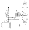
- a device shown there has a storage tank 1 for a supply of a cryogenic gas in its liquid phase.
- the liquid gas is liquid nitrogen, liquid oxygen or liquid argon.
- the storage tank 1 is connected by a liquid gas line 2 to the inlet side 3 of an evaporator 4, on the outlet side 5 of which an outlet (not shown in detail) is provided for removing a desired amount of electricity from the gaseous phase of the gas supply stored in the storage tank 1.
- the storage tank 1 and the evaporator 4 are installed outdoors, whereby the latter is in heat exchange with the ambient air.
- a first control valve arrangement comprising two control valves 6, 7 connected in series is inserted into the liquid gas line 2, one of which is closer to the storage tank 1
- Control valve 6 of the branching off of a secondary flow of the liquid gas flow flowing from the storage tank 1 to the evaporator 4 and the control valve 7 closer to the evaporator 4 serves to return the secondary flow into the liquid gas line 2 leading to the evaporator 4.
- the bypass branched off from the first control valve arrangement is connected to a first circuit 8 of a heat exchanger 9, the second circuit 10 of which is in thermal contact with the first circuit 8 via a buffer medium provided in the heat exchanger 9 (FIG. 2, reference number 11).
- a heat transfer medium from a process providing waste heat is fed to the second circuit 10 via a second control valve arrangement.
- the heat transfer medium emerging from a waste heat generator symbolically represented in FIG. 1 under reference number 12 reaches via a feed line 13 to an input connection of a control valve 14 of the second control valve arrangement, from whose output connection the heat transfer medium is branched into the second circuit 10.
- the output of the second circuit 10 is connected to a first input of a further control valve 15 of the second control valve arrangement, this first input of the further control valve 15 being connected in a corresponding control position to a first output which is connected via a line 16 to a first input of a other control valve 17 of the second control valve arrangement is connected.
- the other output of the control valve 14 is connected via a line 18 to a second input of the further control valve 15, while an output of the other control valve 17 is returned to the waste heat generator 12 via a return line 19.
- the outlet of the refrigeration generator 21 is returned to a second inlet of the other control valve 17 by means of a return line 22, this second inlet being connected to the outlet of the other control valve 17 in a suitable control position.
- the first circuit 8 is guided in a tube 23 which is surrounded at a radial distance by an outer jacket 24, from the outside of which cooling lugs 25 extend.
- the second circuit 10 runs within an area of the heat exchanger 9 enclosed by a wall 26 and thereby covers the areas of the outer jacket 24 arranged within the wall 26.
- the space 27 delimited between the tube 23 and the outer jacket 24 is filled with the buffer medium 11.
- the buffer medium 11 has a phase transition, the transition temperature of which is at least, but preferably above, the vaporization temperature of the liquid gas.
- a control device not shown in the drawing, detects the temperature profile of the buffer medium 11 in the region of its transition temperature as a function of the characteristic pressure or temperature profile of the buffer medium 11 prevailing at a phase transition and controls the first and second control valve arrangements in such a way that they are independent of the per unit time the amount of gas removed from the evaporator 5, on the one hand, the temperature of the buffer medium 11 does not drop below its transition temperature and, on the other hand, the heat transfer medium flowing in from the waste heat generator 12 does not exceed its desired cooling temperature determined by the temperature of the buffer medium.
- the device works in such a way that a liquid gas flow corresponding to a desired flow quantity of the gaseous phase that can be set on the output side 5 flows from the storage tank 1 into the liquid gas line 2.
- the control device adjusts the two control valves 6, 7 of the first control valve arrangement in such a way that the amount of current in the heat exchanger 9 that is branched off in the first circuit 8 does not result in the conversion temperature of the buffer medium 11 falling below.
- the flow of the liquid gas branched off in the first circuit 8 in the heat exchanger 9 is converted into its gaseous phase by heat transfer to the second circuit 10, while the non-branched residual flow, which can also be zero, flows through the control valves 6 and 7 and in which Evaporator 4 is converted into the gaseous phase.
- the gaseous phase in the desired amount of electricity is thus available on the output side 5 in all circumstances.
- control device also adjusts the second control valve arrangement.
- the control device As long as the amount of heat transferred from the second circuit 10 in the heat exchanger 9 to the first circuit 8 is sufficient to cool the entire heat transfer medium supplied, the heat transfer medium flowing through the flow line 13 is let through in the control valve 14 from its inlet to its one outlet and thus flows through the second circuit 10 back to the further control valve 15 which, because of its setting brought about by the control device, allows the incoming heat transfer medium to pass from its first input to its first output and leads via line 16 to the first input of the other control valve 17, which in this control state leads to the output is switched through and therefore returns the heat transfer medium via the return line 19 to the waste heat generator 12.
- the control device opens a circuit branch for the heat transfer medium from the other outlet of the control valve 14 through line 18 to the second input of the further Control valve 15 and through this to its second outlet, so that a corresponding portion of the heat transfer medium reaches the refrigeration generator 21 via the flow line 20.
- the other control valve 17 By setting the other control valve 17 accordingly, the cooled portion of the heat transfer medium arriving on the return line 22 passes from the second input of the other control valve 17 to its outlet and is thereby fed into the return line 19 to the waste heat generator 12.
Landscapes
- Engineering & Computer Science (AREA)
- Mechanical Engineering (AREA)
- General Engineering & Computer Science (AREA)
- Chemical & Material Sciences (AREA)
- Combustion & Propulsion (AREA)
- Physics & Mathematics (AREA)
- Thermal Sciences (AREA)
- Filling Or Discharging Of Gas Storage Vessels (AREA)
Applications Claiming Priority (2)
| Application Number | Priority Date | Filing Date | Title |
|---|---|---|---|
| DE3936940 | 1989-11-06 | ||
| DE3936940A DE3936940A1 (de) | 1989-11-06 | 1989-11-06 | Verfahren und vorrichtung zur erzeugung der gasfoermigen phase aus einem in seiner fluessigen phase gelagerten gasvorrat |
Publications (2)
| Publication Number | Publication Date |
|---|---|
| EP0427112A1 true EP0427112A1 (fr) | 1991-05-15 |
| EP0427112B1 EP0427112B1 (fr) | 1994-02-02 |
Family
ID=6392978
Family Applications (1)
| Application Number | Title | Priority Date | Filing Date |
|---|---|---|---|
| EP19900120933 Expired - Lifetime EP0427112B1 (fr) | 1989-11-06 | 1990-10-31 | Procédé et dispositif de production de la phase gazeuse d'un volume de liquide stocké dans la phase liquide |
Country Status (2)
| Country | Link |
|---|---|
| EP (1) | EP0427112B1 (fr) |
| DE (2) | DE3936940A1 (fr) |
Cited By (8)
| Publication number | Priority date | Publication date | Assignee | Title |
|---|---|---|---|---|
| EP0849550A1 (fr) * | 1996-12-18 | 1998-06-24 | Messer Griesheim Gmbh | Système de réfrigération à gaz liquifié pour le refroidissement à basse température d'une charge |
| EP0922916A3 (fr) * | 1997-12-12 | 1999-09-15 | Messer Griesheim Gmbh | Procédé et dispositif de refroidissement d'un caloporteur |
| EP1030135A1 (fr) * | 1999-02-20 | 2000-08-23 | Lauda Dr. R. Wobser GmbH & Co. KG | Procédé et dispositif pour le refroidissement controlée utilisant l'evaporation d'azote liquide |
| WO2001016538A1 (fr) * | 1999-09-01 | 2001-03-08 | Messer Griesheim Gmbh | Procede et dispositif pour l'utilisation du froid d'un gaz liquefie a basse temperature |
| WO2008116723A1 (fr) * | 2007-03-28 | 2008-10-02 | L'air Liquide Societe Anonyme Pour L'etude Et L'exploitation Des Procedes Georges Claude | Procédé et dispositif de réfrigération d'un entrepôt frigorifique et véhicule de réfrigération associé |
| EP2474797A1 (fr) * | 2011-01-11 | 2012-07-11 | Thilo Rießner | Procédé et dispositif destinés à la climatisation de bâtiment |
| EP3333494A1 (fr) * | 2016-12-08 | 2018-06-13 | Linde Aktiengesellschaft | Procédé, installation et système d'amélioration de l'air dans un bâtiment |
| CN119983148A (zh) * | 2025-03-27 | 2025-05-13 | 大连大特气体有限公司 | 一种相变制气装置及方法 |
Families Citing this family (1)
| Publication number | Priority date | Publication date | Assignee | Title |
|---|---|---|---|---|
| CN110806052A (zh) * | 2019-11-20 | 2020-02-18 | 陈力群 | 一种冷却循环水系统 |
Citations (4)
| Publication number | Priority date | Publication date | Assignee | Title |
|---|---|---|---|---|
| FR1599608A (fr) * | 1968-01-11 | 1970-07-15 | ||
| DE2813509A1 (de) * | 1978-03-29 | 1979-10-11 | Stuckey | Verdampfer fuer eine kuehlanlage |
| FR2582785A1 (fr) * | 1985-04-26 | 1986-12-05 | Agliani Philippe | Installation autonome de refroidissement de fluide gazeux tel que de l'air |
| DE3818121A1 (de) * | 1988-05-27 | 1989-11-30 | Linde Ag | Verfahren und vorrichtung zur zeitlich unabhaengigen nutzung der kaelte und des erwaermten zustandes eines kalten mediums |
-
1989
- 1989-11-06 DE DE3936940A patent/DE3936940A1/de not_active Withdrawn
-
1990
- 1990-10-31 EP EP19900120933 patent/EP0427112B1/fr not_active Expired - Lifetime
- 1990-10-31 DE DE90120933T patent/DE59004507D1/de not_active Expired - Fee Related
Patent Citations (4)
| Publication number | Priority date | Publication date | Assignee | Title |
|---|---|---|---|---|
| FR1599608A (fr) * | 1968-01-11 | 1970-07-15 | ||
| DE2813509A1 (de) * | 1978-03-29 | 1979-10-11 | Stuckey | Verdampfer fuer eine kuehlanlage |
| FR2582785A1 (fr) * | 1985-04-26 | 1986-12-05 | Agliani Philippe | Installation autonome de refroidissement de fluide gazeux tel que de l'air |
| DE3818121A1 (de) * | 1988-05-27 | 1989-11-30 | Linde Ag | Verfahren und vorrichtung zur zeitlich unabhaengigen nutzung der kaelte und des erwaermten zustandes eines kalten mediums |
Cited By (9)
| Publication number | Priority date | Publication date | Assignee | Title |
|---|---|---|---|---|
| EP0849550A1 (fr) * | 1996-12-18 | 1998-06-24 | Messer Griesheim Gmbh | Système de réfrigération à gaz liquifié pour le refroidissement à basse température d'une charge |
| EP0922916A3 (fr) * | 1997-12-12 | 1999-09-15 | Messer Griesheim Gmbh | Procédé et dispositif de refroidissement d'un caloporteur |
| EP1030135A1 (fr) * | 1999-02-20 | 2000-08-23 | Lauda Dr. R. Wobser GmbH & Co. KG | Procédé et dispositif pour le refroidissement controlée utilisant l'evaporation d'azote liquide |
| WO2001016538A1 (fr) * | 1999-09-01 | 2001-03-08 | Messer Griesheim Gmbh | Procede et dispositif pour l'utilisation du froid d'un gaz liquefie a basse temperature |
| WO2008116723A1 (fr) * | 2007-03-28 | 2008-10-02 | L'air Liquide Societe Anonyme Pour L'etude Et L'exploitation Des Procedes Georges Claude | Procédé et dispositif de réfrigération d'un entrepôt frigorifique et véhicule de réfrigération associé |
| EP2474797A1 (fr) * | 2011-01-11 | 2012-07-11 | Thilo Rießner | Procédé et dispositif destinés à la climatisation de bâtiment |
| EP3333494A1 (fr) * | 2016-12-08 | 2018-06-13 | Linde Aktiengesellschaft | Procédé, installation et système d'amélioration de l'air dans un bâtiment |
| WO2018103896A1 (fr) | 2016-12-08 | 2018-06-14 | Linde Aktiengesellschaft | Procédé, installation et système permettant d'améliorer la qualité de l'air dans un bâtiment |
| CN119983148A (zh) * | 2025-03-27 | 2025-05-13 | 大连大特气体有限公司 | 一种相变制气装置及方法 |
Also Published As
| Publication number | Publication date |
|---|---|
| DE59004507D1 (de) | 1994-03-17 |
| EP0427112B1 (fr) | 1994-02-02 |
| DE3936940A1 (de) | 1991-05-08 |
Similar Documents
| Publication | Publication Date | Title |
|---|---|---|
| DE3427601C2 (fr) | ||
| EP3017238B1 (fr) | Dispositif de refroidissement d'un dissipateur avec un liquide surrefroidi dans un circuit de refroidissement | |
| DE69413493T2 (de) | Kühlsystem für die Eintrittsluft in eine Gasturbine | |
| DE2218307C3 (de) | Verfahren zum Verdampfen eines strömenden verflüssigten kryogenen Mediums, insbesondere von verflüssigtem Erdgas | |
| DE69211237T2 (de) | Vakuumbehälter mit einem gekühlten Element | |
| DE2555578C2 (de) | Verfahren und Vorrichtung zum Abkühlen von Gegenständen oder Stoffen | |
| DE3314472C2 (fr) | ||
| DE1551617A1 (de) | Naturgas-Verfluessigung mit gesteuertem BTU-Gehalt | |
| DE19914778A1 (de) | Supraleitende Magnetvorrichtung | |
| EP1533116B1 (fr) | Dispositif pour contrôler la température d'une machine à imprimer | |
| EP0427112B1 (fr) | Procédé et dispositif de production de la phase gazeuse d'un volume de liquide stocké dans la phase liquide | |
| DE2606072A1 (de) | Verfahren und anlage zur steuerung der temperatur in mehreren raeumen, die wechselseitig unterschiedlichen und sich veraendernden waermebedarf haben, wobei einige der raeume normalerweise einen kuehlbedarf haben | |
| DE69108973T2 (de) | Verfahren und Vorrichtung zur Produktion gasförmigen Stickstoffs und System zu dessen Bereitstellung. | |
| DE4200688C1 (fr) | ||
| DE2730155A1 (de) | Verfahren zur kaelteerzeugung im bereich von kryogentemperaturen | |
| DE102007001658A1 (de) | Verfahren und Vorrichtung zur fraktionierten Kryokondensation | |
| EP3749903B1 (fr) | Procédé et dispositif de refroidissement d'un porteur de courant supraconducteur | |
| DE102010028750B4 (de) | Verlustarme Kryostatenanordnung | |
| DE3341853C2 (de) | Einrichtung zum Kühlen von Innenräumen | |
| DE10115937A1 (de) | Verdampfer zum Erzeugen von Speisegas für eine Lichtbogenkammer | |
| EP4446680A2 (fr) | Procédé et dispositif de liquéfaction de gaz | |
| DE1941495A1 (de) | Kuehlgeraet | |
| DE2114538A1 (de) | Verfahren zur Kühlung eines elektrischen Organes in einer durch Wärmeschilder thermisch isolierten Kammer | |
| EP1030135B1 (fr) | Procédé pour le refroidissement controlé utilisant l'evaporation d'azote liquide | |
| EP3322947B1 (fr) | Procédé de refroidissement d'un flux de traitement |
Legal Events
| Date | Code | Title | Description |
|---|---|---|---|
| PUAI | Public reference made under article 153(3) epc to a published international application that has entered the european phase |
Free format text: ORIGINAL CODE: 0009012 |
|
| AK | Designated contracting states |
Kind code of ref document: A1 Designated state(s): BE DE FR NL |
|
| 17P | Request for examination filed |
Effective date: 19911115 |
|
| 17Q | First examination report despatched |
Effective date: 19930601 |
|
| GRAA | (expected) grant |
Free format text: ORIGINAL CODE: 0009210 |
|
| AK | Designated contracting states |
Kind code of ref document: B1 Designated state(s): BE DE FR NL |
|
| REF | Corresponds to: |
Ref document number: 59004507 Country of ref document: DE Date of ref document: 19940317 |
|
| ET | Fr: translation filed | ||
| PG25 | Lapsed in a contracting state [announced via postgrant information from national office to epo] |
Ref country code: BE Effective date: 19941031 |
|
| PLBE | No opposition filed within time limit |
Free format text: ORIGINAL CODE: 0009261 |
|
| STAA | Information on the status of an ep patent application or granted ep patent |
Free format text: STATUS: NO OPPOSITION FILED WITHIN TIME LIMIT |
|
| 26N | No opposition filed | ||
| BERE | Be: lapsed |
Owner name: WESTFALEN A.G. Effective date: 19941031 |
|
| PG25 | Lapsed in a contracting state [announced via postgrant information from national office to epo] |
Ref country code: NL Effective date: 19950501 |
|
| NLV4 | Nl: lapsed or anulled due to non-payment of the annual fee | ||
| PG25 | Lapsed in a contracting state [announced via postgrant information from national office to epo] |
Ref country code: FR Effective date: 19950630 |
|
| PG25 | Lapsed in a contracting state [announced via postgrant information from national office to epo] |
Ref country code: DE Effective date: 19950701 |
|
| REG | Reference to a national code |
Ref country code: FR Ref legal event code: ST |