EP0427131A2 - Antenne de radar directive avec focalisation de l'énergie électromagnétique, pour télécommunications - Google Patents
Antenne de radar directive avec focalisation de l'énergie électromagnétique, pour télécommunications Download PDFInfo
- Publication number
- EP0427131A2 EP0427131A2 EP90121021A EP90121021A EP0427131A2 EP 0427131 A2 EP0427131 A2 EP 0427131A2 EP 90121021 A EP90121021 A EP 90121021A EP 90121021 A EP90121021 A EP 90121021A EP 0427131 A2 EP0427131 A2 EP 0427131A2
- Authority
- EP
- European Patent Office
- Prior art keywords
- radar antenna
- electromagnetic energy
- antenna according
- cavity
- frequency
- Prior art date
- Legal status (The legal status is an assumption and is not a legal conclusion. Google has not performed a legal analysis and makes no representation as to the accuracy of the status listed.)
- Withdrawn
Links
Images
Classifications
-
- H—ELECTRICITY
- H01—ELECTRIC ELEMENTS
- H01Q—ANTENNAS, i.e. RADIO AERIALS
- H01Q19/00—Combinations of primary active antenna elements and units with secondary devices, e.g. with quasi-optical devices, for giving the antenna a desired directional characteristic
- H01Q19/06—Combinations of primary active antenna elements and units with secondary devices, e.g. with quasi-optical devices, for giving the antenna a desired directional characteristic using refracting or diffracting devices, e.g. lens
- H01Q19/062—Combinations of primary active antenna elements and units with secondary devices, e.g. with quasi-optical devices, for giving the antenna a desired directional characteristic using refracting or diffracting devices, e.g. lens for focusing
-
- H—ELECTRICITY
- H01—ELECTRIC ELEMENTS
- H01Q—ANTENNAS, i.e. RADIO AERIALS
- H01Q1/00—Details of, or arrangements associated with, antennas
- H01Q1/12—Supports; Mounting means
- H01Q1/22—Supports; Mounting means by structural association with other equipment or articles
- H01Q1/24—Supports; Mounting means by structural association with other equipment or articles with receiving set
- H01Q1/247—Supports; Mounting means by structural association with other equipment or articles with receiving set with frequency mixer, e.g. for direct satellite reception or Doppler radar
-
- H—ELECTRICITY
- H01—ELECTRIC ELEMENTS
- H01Q—ANTENNAS, i.e. RADIO AERIALS
- H01Q13/00—Waveguide horns or mouths; Slot antennas; Leaky-waveguide antennas; Equivalent structures causing radiation along the transmission path of a guided wave
- H01Q13/10—Resonant slot antennas
- H01Q13/18—Resonant slot antennas the slot being backed by, or formed in boundary wall of, a resonant cavity ; Open cavity antennas
Definitions
- the present invention relates to an innovative directive radar antenna for telecommunications, with electromagnetic energy compression, characterized by high directionality and gain with respect to other systems, while having very small dimensions.
- the aim of the present invention is to overcome the above mentioned drawbacks by providing a directive radar antenna of high directivity, gain and power efficiency and a very small size and weight construction.
- a main object of the present invention is to provide such a radar antenna which can be easily and simply fitted for transmitting a light radiation.
- the antenna according to the invention comprises a front lenticular body made of plastics including a plurality of electromagnetic cavities, in which the electromagnetic energy self-charges.
- the bottom of the antenna passive cavity which is frontally closed by the lenticular body made of plastics, is defined by a metallic plate provided with a hole or a central opening from which energy is irradiated and self-accumulates by successive feedbacks in the lenticular body of the antenna.
- the pyramid-like shape with cambered walls of the front lenticular body in which the compression of the electromagnetic energy occurs and which provides an output power of high directionality, can have any spatial configuration, for example an ogive-like shape having a circular base, or a pyramid-like shape having a square or generally polygonal base; more generally, it can be defined as a pyramidal shape or spherical profile and can be defined by the rotation of an arc of circumference.
- the possibility of positioning a laser source at the center of the antenna allows moreover to convert said antenna into a highly directive source of luminous power and therefore to use the antenna as a luminous power source for different technological purposes or for other applications.
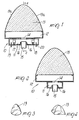
- the antenna 10 comprises a main cavity 11 constituted by a metallic box-like body defining a sort of rectangular wave guide, also termed hereinafter “active cavity”, which is associated with a secondary cavity 12, also termed “energy reflection cavity” or “passive cavity”, frontally closed by a lenticular body 13, made of a plastic material or another suitable material, having a wedge-shaped configuration and a particular arrangement.
- active cavity a sort of rectangular wave guide
- secondary cavity 12 also termed “energy reflection cavity” or “passive cavity”
- lenticular body 13 made of a plastic material or another suitable material, having a wedge-shaped configuration and a particular arrangement.
- the active cavity 11, in which the electromagnetic energy is generated, is connected to the secondary cavity 12 through a central passage 14 defined by appropriate holes or superimposed openings in the back wall which delimits the secondary cavity 12 and in the upper wall of the wave guide
- a cylindrical body 15 axially adjustable in its position for example by screwing it into two threaded lateral blocks 16, as schematically illustrated, for the adjustment of the operating frequency of the antenna.
- a transmitter diode or gun diode 17 and respectively a receiver or detector 18 provided with respective frequency adjustment screws 19 and extending into the cavity 11.
- the distance of the adjustment screws 19 and 20 from the end walls of the cavity 11 and respectively from the transmitter diode and from the detector diode 17, 18 is one quarter of the wavelength of the generated or received frequency, whereas the distance of the transmitter diode and of the receiver 18 is half the wavelength of the chosen operating frequency.
- the secondary cavity 12 is connected to the main cavity or active cavity 11 through the central passage 14, and is defined by a flat element or by a planar back wall conveniently spaced by means of lateral walls from the lenticular front closing body 13.
- the lenticular body 13 has a specifically designed shape which is adapted for allowing the self-compression of the electromagnetic energy and a highly directive output thereof at the front apex.
- Said body is therefore characterized by lateral walls 13a which have a cambered shape or are delimited by portions of spherical surfaces, as schematically illustrated, or by an ogive-like or pyramid-like shape, the base whereof, as shown in figures 3 and 4 merely by way of example, can be circular, square or polygonal depending on the requirements.
- figure 3 illustrates a pyramid-like shape with a circular base with a spherical profile
- figure 4 illustrates a pyramid-like shape with a square base and with cambered surfaces only on two sides.
- the particular combination and configuration of the two cavities 11 and 12 and of the front lenticular body 13 provide the disclosed radar antenna with a high gain and directionality, as well a high output power efficiency, while keeping the dimensions of the antenna to a minimum.
- the centralized output of the energy at the apex of the lenticular body furthermore allows to use the radar antenna according to the present invention as a luminous energy source, for example by replacing the central cylindrical body 15 of the active or main chamber with a suitable laser source.
- the operation of the antenna according to the present invention is characterized by a series of internal reflections, in the cavities and in the front lenticular body, of the electromagnetic energy, which self-charges or accumulates and compresses and is conveyed toward the apex from which it is irradiated in a highly directive manner.
Landscapes
- Engineering & Computer Science (AREA)
- Radar, Positioning & Navigation (AREA)
- Remote Sensing (AREA)
- Geophysics And Detection Of Objects (AREA)
- Burglar Alarm Systems (AREA)
- Radar Systems Or Details Thereof (AREA)
- Aerials With Secondary Devices (AREA)
Applications Claiming Priority (2)
| Application Number | Priority Date | Filing Date | Title |
|---|---|---|---|
| IT02229289A IT1236669B (it) | 1989-11-07 | 1989-11-07 | Antenna radar direttiva, a compressione di energia elettromagnetica, per telecomunicazione |
| IT2229289 | 1989-11-07 |
Publications (2)
| Publication Number | Publication Date |
|---|---|
| EP0427131A2 true EP0427131A2 (fr) | 1991-05-15 |
| EP0427131A3 EP0427131A3 (en) | 1991-10-16 |
Family
ID=11194272
Family Applications (1)
| Application Number | Title | Priority Date | Filing Date |
|---|---|---|---|
| EP19900121021 Withdrawn EP0427131A3 (en) | 1989-11-07 | 1990-11-02 | Directive radar antenna with electromagnetic energy compression, for telecommunications |
Country Status (2)
| Country | Link |
|---|---|
| EP (1) | EP0427131A3 (fr) |
| IT (1) | IT1236669B (fr) |
Cited By (4)
| Publication number | Priority date | Publication date | Assignee | Title |
|---|---|---|---|---|
| EP0636899A3 (fr) * | 1993-07-31 | 1997-08-13 | Plessey Semiconductors Ltd | Senseur doppler à micro-ondes. |
| RU2189677C2 (ru) * | 2000-12-19 | 2002-09-20 | 16 Центральный научно-исследовательский испытательный институт МО РФ | Кольцевая щелевая антенна |
| US7548190B2 (en) * | 2006-12-15 | 2009-06-16 | Franco Baldi | Obstacle sensor operating by collimation and focusing of the emitted wave |
| EP2571064A1 (fr) | 2011-09-13 | 2013-03-20 | Multi.Bay SA | Concentrateur solaire hybride comprenant des moyens de concentration, un dispositif photovoltaïque et un dispositif thermique pour la génération d'électricité |
Family Cites Families (4)
| Publication number | Priority date | Publication date | Assignee | Title |
|---|---|---|---|---|
| US2895127A (en) * | 1954-07-20 | 1959-07-14 | Rca Corp | Directive diplex antenna |
| GB1573300A (en) * | 1977-03-09 | 1980-08-20 | Aei Semiconductors Ltd | Microwave oscillators |
| US4187507A (en) * | 1978-10-13 | 1980-02-05 | Sperry Rand Corporation | Multiple beam antenna array |
| FR2448230A1 (fr) * | 1979-02-02 | 1980-08-29 | Thomson Csf | Source rayonnante a cavite ouverte excitee par un dipole |
-
1989
- 1989-11-07 IT IT02229289A patent/IT1236669B/it active IP Right Grant
-
1990
- 1990-11-02 EP EP19900121021 patent/EP0427131A3/en not_active Withdrawn
Cited By (4)
| Publication number | Priority date | Publication date | Assignee | Title |
|---|---|---|---|---|
| EP0636899A3 (fr) * | 1993-07-31 | 1997-08-13 | Plessey Semiconductors Ltd | Senseur doppler à micro-ondes. |
| RU2189677C2 (ru) * | 2000-12-19 | 2002-09-20 | 16 Центральный научно-исследовательский испытательный институт МО РФ | Кольцевая щелевая антенна |
| US7548190B2 (en) * | 2006-12-15 | 2009-06-16 | Franco Baldi | Obstacle sensor operating by collimation and focusing of the emitted wave |
| EP2571064A1 (fr) | 2011-09-13 | 2013-03-20 | Multi.Bay SA | Concentrateur solaire hybride comprenant des moyens de concentration, un dispositif photovoltaïque et un dispositif thermique pour la génération d'électricité |
Also Published As
| Publication number | Publication date |
|---|---|
| IT1236669B (it) | 1993-03-25 |
| IT8922292A0 (it) | 1989-11-07 |
| IT8922292A1 (it) | 1991-05-07 |
| EP0427131A3 (en) | 1991-10-16 |
Similar Documents
| Publication | Publication Date | Title |
|---|---|---|
| US10224638B2 (en) | Lens antenna | |
| US3755815A (en) | Phased array fed lens antenna | |
| EP1635422B1 (fr) | Dispositif d'antenne a reseau de lentilles electromagnetique | |
| US7075492B1 (en) | High performance reflector antenna system and feed structure | |
| US4994817A (en) | Annular slot antenna | |
| KR20100040216A (ko) | 고이득을 위한 카세그레인 안테나 | |
| CN111211423A (zh) | 一种超宽带多波束柱形透镜天线 | |
| Allen et al. | Reduction of orbital angular momentum radio beam divergence using a 3D printed planar graded index lenses | |
| US4305078A (en) | Multifrequency series-fed edge slot antenna | |
| EP0427131A2 (fr) | Antenne de radar directive avec focalisation de l'énergie électromagnétique, pour télécommunications | |
| US4400701A (en) | Common antenna for primary and secondary radar | |
| EP3357125B1 (fr) | Antenne en forme de cuvette | |
| US2594871A (en) | Antenna | |
| US6700549B2 (en) | Dielectric-filled antenna feed | |
| US3182322A (en) | Radar antennae | |
| US9035842B2 (en) | Miniature horn interrogator antenna with internal sum/difference combiner | |
| US2846680A (en) | Directive antennas | |
| Bagheri et al. | Radar antenna gain improvement using 3D-printed dielectric lens and metamaterial-inspired superstrates | |
| CA1233246A (fr) | Radar aeroporte a balayage lateral | |
| Anupama et al. | Bowel Shaped and Loaded Conical Dielectric Substrate Horn Antenna for Ultra Wide Band Operation | |
| Singh et al. | Performance comparison of phase shifting surface lens antenna with other lens antennas | |
| US20250284036A1 (en) | Gradient-index lens and method of manufacturing | |
| Scattone et al. | Generation of a cosecant-squared radiation pattern with a superstrate-like leaky-wave antenna | |
| Bagheri et al. | Radar antenna gain improvement using an integrated in-package dielectric rod superstrate | |
| US20240413541A1 (en) | Antenna device |
Legal Events
| Date | Code | Title | Description |
|---|---|---|---|
| PUAI | Public reference made under article 153(3) epc to a published international application that has entered the european phase |
Free format text: ORIGINAL CODE: 0009012 |
|
| AK | Designated contracting states |
Kind code of ref document: A2 Designated state(s): AT BE CH DE DK ES FR GB GR IT LI LU NL SE |
|
| PUAL | Search report despatched |
Free format text: ORIGINAL CODE: 0009013 |
|
| AK | Designated contracting states |
Kind code of ref document: A3 Designated state(s): AT BE CH DE DK ES FR GB GR IT LI LU NL SE |
|
| STAA | Information on the status of an ep patent application or granted ep patent |
Free format text: STATUS: THE APPLICATION IS DEEMED TO BE WITHDRAWN |
|
| 18D | Application deemed to be withdrawn |
Effective date: 19920417 |