EP0427217A2 - Système de séchage - Google Patents
Système de séchage Download PDFInfo
- Publication number
- EP0427217A2 EP0427217A2 EP90121251A EP90121251A EP0427217A2 EP 0427217 A2 EP0427217 A2 EP 0427217A2 EP 90121251 A EP90121251 A EP 90121251A EP 90121251 A EP90121251 A EP 90121251A EP 0427217 A2 EP0427217 A2 EP 0427217A2
- Authority
- EP
- European Patent Office
- Prior art keywords
- cylinders
- jacket
- drying device
- air
- belt
- Prior art date
- Legal status (The legal status is an assumption and is not a legal conclusion. Google has not performed a legal analysis and makes no representation as to the accuracy of the status listed.)
- Granted
Links
- 238000001035 drying Methods 0.000 title claims abstract description 68
- 239000000463 material Substances 0.000 claims abstract description 46
- 238000009434 installation Methods 0.000 claims abstract description 45
- 238000007664 blowing Methods 0.000 claims description 11
- 238000009423 ventilation Methods 0.000 claims description 7
- 238000010438 heat treatment Methods 0.000 claims description 5
- 239000010959 steel Substances 0.000 claims description 4
- 229910000831 Steel Inorganic materials 0.000 claims description 3
- 230000000630 rising effect Effects 0.000 claims 1
- 230000000694 effects Effects 0.000 description 8
- 230000002349 favourable effect Effects 0.000 description 6
- 239000004744 fabric Substances 0.000 description 3
- 230000015572 biosynthetic process Effects 0.000 description 2
- 238000007789 sealing Methods 0.000 description 2
- 229910001018 Cast iron Inorganic materials 0.000 description 1
- 229910001208 Crucible steel Inorganic materials 0.000 description 1
- 210000004712 air sac Anatomy 0.000 description 1
- 230000008030 elimination Effects 0.000 description 1
- 238000003379 elimination reaction Methods 0.000 description 1
- 238000001704 evaporation Methods 0.000 description 1
- 230000008020 evaporation Effects 0.000 description 1
- 238000002347 injection Methods 0.000 description 1
- 239000007924 injection Substances 0.000 description 1
- 238000012423 maintenance Methods 0.000 description 1
- 238000004519 manufacturing process Methods 0.000 description 1
- 238000000926 separation method Methods 0.000 description 1
- 239000003381 stabilizer Substances 0.000 description 1
- XLYOFNOQVPJJNP-UHFFFAOYSA-N water Substances O XLYOFNOQVPJJNP-UHFFFAOYSA-N 0.000 description 1
Images


Classifications
-
- D—TEXTILES; PAPER
- D21—PAPER-MAKING; PRODUCTION OF CELLULOSE
- D21F—PAPER-MAKING MACHINES; METHODS OF PRODUCING PAPER THEREON
- D21F5/00—Dryer section of machines for making continuous webs of paper
- D21F5/02—Drying on cylinders
- D21F5/04—Drying on cylinders on two or more drying cylinders
- D21F5/042—Drying on cylinders on two or more drying cylinders in combination with suction or blowing devices
Definitions
- the invention relates to a drying device for high-speed moving material, in particular paper or fibrous webs, which expediently consists of a series of steam-heated cylinders, in particular essentially on the same horizontal plane, and expediently a series of unheated cylinders, approximately in the spaces between these cylinders , in particular also in a deflection roller mounted either below or above the above-mentioned horizontal plane, the jacket of which is perforated and / or provided with grooves, suction of air from these deflection rollers being provided and these cylinders and the deflection rollers being covered with a screen belt are equipped and the web of material on the cylinders is between their jacket and the screen belt or the like, while on the deflection rollers the screen belt comes to rest on the jacket of the rollers and the web of material lies outside on the screen belt.
- DE-OS 3828742 shows, inter alia, a drying group of a paper machine multi-cylinder dryer of the type described in the introduction, in which both deflection rollers, which correspond to the aforementioned guide rollers, and combined blower suction boxes arranged above the deflection rollers are connected to a vacuum generator. These blow-suction boxes are also connected to a pressure generator and have side flanks with nozzle openings through which air is blown under pressure against the screen belt and paper web runs or pulls freely guided between the cylinders and the deflecting rollers.
- somewhat improved drying is achieved through the drying wire because, in particular with regard to the negative pressure applied to the inside of the perforated jacket of the deflecting rollers, the moisture removal is improved.
- this improvement does not yet adequately meet practical requirements.
- the loss at Drying performance due to the loss of an entire row of cylinders cannot be compensated for by far.
- the invention is based on a new concept for a high-speed multi-cylinder dryer section, which on the one hand ensures the good and safe guidance of the material, in particular paper web, and on the other hand avoids the disadvantage of the unsatisfactory drying performance.
- the goals set are achieved by arranging an airflow and therefore material web-guiding flow installation in the intermediate spaces between the jackets of the cylinder (s) and the deflection rollers on the part not touched by the screen belt reached of the jacket of the deflecting roller, this flow installation having the completely closed side flanks facing the respectively adjacent wire belt run and an undivided inner space which is connected to a vacuum suction device.
- the flow installation according to the invention has completely closed side flanks, that is to say the nozzle openings provided in the known blow-suction boxes mentioned above do not penetrate and thus interrupt the side flanks, the associated risk of a disturbance of the runs or trains running freely between cylinders and deflection rollers is the Material or wire belt web switched off. Since, according to the invention, the entire interior of the flow installation is used for the suction power, that is no longer for pressurized air, according to the invention a considerable additional suction power is provided with less effort - no compressed air source is required for the flow installation - which does not only relate to the total drying capacity, but also has a favorable effect on the management of material and screen belt.
- the guiding effect is additionally improved according to the invention if the distance between the side flanks of the flow installation and the respectively adjacent sieve belt strand in the direction of its movement increases, in particular steadily. Due to the resulting diffuser-like expansion of the air flow or space between these side flanks and the free material web or screen belt runs in the The area of the free material web or screen belt runs succeeds in controlling the air currents in the area of the freely moving runs or the free trains of the screen belt or the material web and to ensure good guidance of the material web in this area, in particular its lifting from the Avoid screen belt as far as possible.
- a further improvement according to the invention can act in the same sense, which consists in the fact that the flow installation is at a smaller distance from the wire belt strand running onto the deflecting roller than from the wire belt strand running off this roller.
- the sieve belt it may be expedient to limit the air entrained by the sieve belt in order to avoid excess pressure and thus local lifting of the material web; This can be achieved in that in the area of the back facing away from the jacket of the associated deflecting roller, in particular the upper side, of the flow installation, an air separating device or seal extending into the gap between the flow installation and the up and / or down running belt section is provided.
- the suction effect of the deflecting rollers and thus the drying effect can be further enhanced according to the invention if the flow installation on the side facing the jacket of the associated deflecting roller is sealed at its edges with respect to this jacket.
- Material web guidance or suction effect and drying effect can additionally be made more favorable according to the invention if the deflecting roller (s) is or are displaced from the plane of symmetry of the intermediate spaces of the cylinders to the wire belt run running onto the deflecting roller (s).
- a further improvement in the drying performance and the screen belt, in particular material web guidance is achieved in that an air-blowing device is arranged on the side of the deflecting rollers opposite the flow installation, which at least partially covers the jacket of the deflecting roller touched by the screen belt or the like , for example completely wrapped around with movement play.
- Movement play is understood to mean a small distance between the blow-out surface of this air-blowing device facing the jacket of the deflecting roller, which just barely allows the sieve belt and the material webs in question to move through in the gap between the air-blowing device and the deflecting roller moving with the sieve belt.
- the air bubble device is preferably provided with a lifting device so that there is no blockage of the intermediate space when the paper web is being carried out or when it is torn off.
- the lifting device can lift the air bladder device on one or both sides completely or partially from the cylinder surface. There should therefore be a gap which is still just sufficient, but unnecessary play or too great a distance should be avoided in order to bring the blowing performance as unimpeded as possible to the material web moving past with the sieve belt, in order to suction through the openings or into the Support the grooves of the deflection roller accordingly.
- a strong drying effect is achieved, through which the loss of a row of cylinders can be fully or partially compensated for. This also results in good and safe guidance of the material web in the area of the deflection roller.
- a further increase in the drying capacity can be achieved if (one) further air blower devices or (a) blow box are provided on the steam-heated cylinders, which also have the introduction of fresh air into the drying device and advantageously have (one) air injection opening (s) that is or are located in the space between adjacent cylinders on the side remote from the associated deflecting roller near one or both cylinders.
- the steam-heated cylinders are designed as high-performance steel cylinders according to AT-PS 387248 or the Austrian patent application A 1512/87.
- the air bubble devices are connected to an air-circulating system which is separate from the rest of the ventilation system of the drying device.
- a common ventilation system is provided for the drying device, the interior space (s) of the flow installation (s) and the deflection roller (s) together on a vacuum generator are connected and if the air bubble device (s) and, if appropriate, the further air bubble device (s) are fed together via an air heating device.
- the diameter of the unheated deflection rollers connected to a vacuum generator is smaller than the diameter of the steam-heated cylinders, e.g. the diameter of the deflecting rollers is approximately 1000 - 1500 mm, the diameter of these cylinders is approximately 1800 mm.
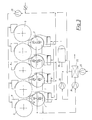
- FIG. 1 shows a drying group with an air-blowing device according to the invention and a flow installation according to the invention, the steam-heated cylinders being arranged higher than the deflecting rollers.
- Fig. 2 shows a similar drying device, but the arrangement of the cylinders and the deflecting rollers is reversed.
- a variant of the air circuit is also shown here.
- 3 illustrates another embodiment variant with an additional air bubble device and a further variant of the air circuit.
- Fig. 4 shows a drying group in which the flow internals, but not the air bubble devices, are provided.
- 5 and 6 show details in the area of the deflecting rollers on an enlarged scale compared to the aforementioned figures, namely FIG. 5 in front view, FIG. 6 as section A-A according to FIG. 5.
- a first dryer group of the dryer section of a paper machine or a part of such a group. It's about single-belt guide groups.
- the press section of the paper machine In front of it there is the press section of the paper machine for practical versions.
- the material or paper web is appropriately in closed guide conveyed from the press section to the dryer section.
- one or more single-wire conveyor guide groups - as shown below - can be provided in the dryer section, followed by one or more two-wire conveyor guide group (s) if necessary.
- a drying group or drying device for high-speed moving material, in particular paper or fibrous webs is first described, specifically with an arrangement with drying cylinders 3 at the top and deflection rollers 2 at the bottom; in a corresponding form, however, it also applies to the reverse arrangement according to FIG. 2 with drying cylinders 3 arranged at the bottom, whereby it may be expedient to move part of the drying groups with the cylinders on top according to FIG. 1 and a part with cylinders below within a drying section Fig. 2 execute.
- a cylinder heated with a heat transfer medium, in particular steam, for paper machines has a metallic core cylinder provided on its surface with a number of grooves, preferably parallel to one another and optionally, in particular partly, parallel to its axis, and the cylinder is heated by Supply of the heat transfer medium, in particular steam, into the grooves.
- the grooves are, for example, machined into the surface of the core cylinder, and a metallic cylindrical outer jacket is drawn onto the core cylinder in a metal-contacting manner, in particular shrink-fitted, with the formation of pressure spaces between the latter and the core cylinder, which can be welded to the core cylinder at its edges, and that Grooves have a continuously - preferably uniformly - changing cross-section over at least part of their length on.
- the lower deflections of the screen belt 15 or the material or paper web 14 are not formed by drying cylinders, as is usually the case, but deflection or guide rollers 2, the diameter of which is somewhat smaller than that of the drying cylinder 3. Typical dimensions are e.g. 1800 mm diameter for the drying cylinder 3 and 1000 - 1500 mm diameter for the deflection rollers 2 below.
- These deflection rollers are provided with a suction device 12 and have a perforated, preferably perforated jacket 13, so that a vacuum or Vacuum arises and thus the material or paper web 14 is held in its lower loop 14 'by this vacuum on the deflection roller.
- the perforation of the deflecting rollers 2 can be distributed unevenly over their outer surface.
- a larger number of perforation openings or bores can be present in the area of the material web edge than in the central area of the web or of the roll shell.
- an air blowing device 1 is arranged, which causes intensive drying in this area by blowing hot air onto the material or paper web 14, 14 '.
- the material web 14 is guided in the entire area of the drying group through the endless, individual sieve belt 15 guided in loops in succession around the cylinders 3 and the deflection rollers 2.
- the shrinkage of the material web, in particular paper web 14, takes place increasingly in the part in which the evaporation of the water takes place. This applies in particular to that free train 14 ⁇ which is then passed through a drying cylinder 3 until it hits the next deflecting roller 2. In order to reduce the shrinkage in this area, it is expedient to make this free train 14 ⁇ particularly short, while the free train 14′′′ following the deflection roller 3 can be somewhat longer.
- a flow installation 4 is provided above the perforated deflecting rollers 2, which essentially serves two purposes: on the one hand, this covers part of the circumference of the perforated deflecting roller 2 that is not in contact with the material web or paper, thus preventing the increased intake of air in this area.
- This has the advantage that the amount of air sucked in is greatly reduced and the maintenance of the vacuum or negative pressure in the suction deflecting rollers 2 is possible with smaller amounts of air sucked off, which in particular brings energetic advantages.
- seals 8,8 ' are also arranged in order to prevent the ingress of air. This can be done either by scraper-like sealing strips, by brushes or similar sealing devices.
- the second purpose of this flow installation 4 relates to the control of the air flows in the area of the free material or paper runs 14 ⁇ , 14 ′′′, (trains) and thus the guidance of the material, in particular paper web 14 in this area.
- the distances between the flow installation 4, i.e. between its completely closed side flanks 4 ', 4 ⁇ and the screen belt 15 on the downward and on the upward running run or train 15', 15 ⁇ selected different sizes.
- the flow installation 4 is not carried out parallel to the dryer fabric 15 or 15 'or 15,, but in an oblique arrangement, so that a diffuser-like expansion for the air flow occurs.
- the arrangement of a seal 9 against the sieve belt 15 ' e.g. in the form of a brush band or an elastic seal.
- This arrangement makes it possible to limit the air entrained by the sieve belt 15, 15 ', so that there is no overpressure in that part where the sieve belt and the material web run onto the lower deflection roller 2; such an overpressure could otherwise lead to a local lifting of the material web 14. That favorable effect is further supported by the fact that part of the air is sucked into the part of the deflecting roller 2 that remains free of the screen belt 15 or the material web 14, so that no disruptive excess pressure can build up.
- suction from the interior of the flow installation 4 is also provided according to the invention.
- the flow installation has an undivided interior, which is connected to a vacuum generator, in particular a fan.
- the false air passing between the flow installation 4 and the deflection roller 2 can also be discharged, or a simpler design of the seals 8, 8 'is possible, since appropriate leakage air quantities can be permitted. In some cases, it will be possible to do without a seal at all.
- the entire flow installation 4 serves as a suction box.
- a combination of the air blowing device 1 and the flow installation 4 on the suction deflecting roller 2 is preferred.
- the arrangement of the roller 2 is favorable not eccentric or shifted below the middle of the space between two drying cylinders 3 in each case.
- the boundary walls 4', 4 'of the flow installation 4 do not run parallel, but slightly obliquely to the dryer 15', 15 'in these areas.
- the seal 8.8 'between the flow installation 4 and deflection roller 2 is recommended.
- the air separation device 9 on the upper edge of the flow installation 4 favors the material web guidance.
- An additional suction 10 of air from the flow installation 4 see also FIG.
- Fig. 2 shows diagrammatically a dryer section which, as is adoptedbuat in Fig. 1 shown substantially, but with a 180 o twisted arrangement, ie with a row of cylinders 3, the level of which lies below the level of the row of deflecting rollers 2.
- the flow internals 4 and the bladder devices 1 are interchanged accordingly in their position.
- Fig. 2 also shows the air cycle, for which reference is made to the arrow lines ending, whereby the air movements are indicated.
- 19 is an air heater, 20, 21, 23 and 24 are fans and 22 is a heat exchanger.
- the air bubble devices 1 for the deflecting rollers 2 are connected to an air-guiding circuit system which is separate from the rest of the ventilation system of the drying device.
- FIG. 3 shows a further variant, in particular with regard to the air flow, the direction of which was again illustrated by arrows.
- An additional air bubble device 11 on a steam-heated cylinder 3 is provided here.
- Fans 20, 23 and 24 are again available, which are designed as suction or pressure blowers, depending on their task.
- a common ventilation system is provided for the drying device, the interior space (s) of the flow installation (s) 4 and the deflection roller (s) 2 being connected together to a vacuum generator 24 and the air blower device (s) ) 1 and optionally the further air bubble device (s) 11 are fed together via an air heating device 19.
- FIG. 4 shows a further embodiment of the invention, which is largely the same as FIG. 1 and the same device parts have been given the same reference numerals as in FIG. 1. However, no air bubble devices are arranged on the side of the deflecting rollers 2 opposite the flow internals 4. The other elements shown in Fig. 1, however, are completely present.
- Fig. 5 shows an enlarged section of the dryer section. It shows in particular the guidance of the paper web 14 and the dryer fabric 15 and the flow installation 4 or its boundary walls 4 ', 4 ⁇ and 4 4. Also are the seal 9 against the sieve belt and the seals 8, 8 'against the deflection roller 2 are shown by way of example.
- Fig. 6 illustrates the section A-A according to Fig. 5.
- the flow installation 4 with the suction 10 and the seals 8 ' is shown schematically.
Landscapes
- Paper (AREA)
- Drying Of Solid Materials (AREA)
- Measuring Pulse, Heart Rate, Blood Pressure Or Blood Flow (AREA)
- Details Of Garments (AREA)
Applications Claiming Priority (2)
| Application Number | Priority Date | Filing Date | Title |
|---|---|---|---|
| AT2582/89 | 1989-11-10 | ||
| AT258289A AT394870B (de) | 1989-11-10 | 1989-11-10 | Trocknungsvorrichtung |
Publications (3)
| Publication Number | Publication Date |
|---|---|
| EP0427217A2 true EP0427217A2 (fr) | 1991-05-15 |
| EP0427217A3 EP0427217A3 (en) | 1991-11-06 |
| EP0427217B1 EP0427217B1 (fr) | 1995-05-24 |
Family
ID=3536883
Family Applications (1)
| Application Number | Title | Priority Date | Filing Date |
|---|---|---|---|
| EP90121251A Expired - Lifetime EP0427217B1 (fr) | 1989-11-10 | 1990-11-07 | Système de séchage |
Country Status (5)
| Country | Link |
|---|---|
| EP (1) | EP0427217B1 (fr) |
| AT (1) | AT394870B (fr) |
| DE (1) | DE59009129D1 (fr) |
| ES (1) | ES2072956T3 (fr) |
| NO (1) | NO179263C (fr) |
Cited By (10)
| Publication number | Priority date | Publication date | Assignee | Title |
|---|---|---|---|---|
| DE4314475A1 (de) * | 1993-05-03 | 1993-12-23 | Voith Gmbh J M | Anordnung zum Führen einer zu trocknenden Bahn |
| WO1996032534A1 (fr) * | 1995-04-12 | 1996-10-17 | Valmet Corporation | Principes applicables a un sechoir et procede de sechage d'une feuille continue de papier ou carton |
| DE19714758A1 (de) * | 1997-04-10 | 1998-10-15 | Voith Sulzer Papiermasch Gmbh | Vorrichtung zum Führen einer Materialbahn |
| WO2007085699A1 (fr) | 2006-01-30 | 2007-08-02 | Metso Paper, Inc. | Procédé et dispositif destinés à la section de séchage d'une machine de fabrication de bandes continues de matières fibreuses, telle qu'une machine à papier ou à carton |
| WO2011076251A2 (fr) | 2009-12-21 | 2011-06-30 | Metso Paper, Inc. | Composant facilitant le passage sur machine |
| WO2017092930A1 (fr) * | 2015-11-30 | 2017-06-08 | Voith Patent Gmbh | Dispositif et procédé de production d'une bande de matière fibreuse |
| WO2017092932A1 (fr) * | 2015-11-30 | 2017-06-08 | Voith Patent Gmbh | Dispositif de fabrication d'une bande de matière fibreuse |
| WO2017092933A1 (fr) * | 2015-11-30 | 2017-06-08 | Voith Patent Gmbh | Dispositif et procédé de production d'une bande de matière fibreuse |
| WO2017092931A1 (fr) * | 2015-11-30 | 2017-06-08 | Voith Patent Gmbh | Dispositif de fabrication d'une bande de matière fibreuse |
| CN111690996A (zh) * | 2020-06-16 | 2020-09-22 | 杭州华创实业有限公司 | 一种包裹丝辐射烘干定型设备及其烘干方法 |
Families Citing this family (3)
| Publication number | Priority date | Publication date | Assignee | Title |
|---|---|---|---|---|
| DE19609213A1 (de) * | 1996-03-09 | 1997-09-11 | Voith Sulzer Papiermasch Gmbh | Maschine zur Herstellung einer Bahn |
| FI126248B (fi) * | 2013-11-06 | 2016-08-31 | Valmet Technologies Inc | Menetelmä ja sovitelma päänviennissä kuiturainakoneen kuivatusosalla |
| DE102023101609A1 (de) * | 2023-01-24 | 2024-04-18 | Voith Patent Gmbh | Maschine und Verfahren zur Herstellung oder Behandlung einer Faserstoffbahn |
Family Cites Families (12)
| Publication number | Priority date | Publication date | Assignee | Title |
|---|---|---|---|---|
| FI53333C (fi) * | 1972-11-13 | 1978-04-10 | Valmet Oy | Torkningscylindergrupp i en flercylindertork foer en materialbana i synnerhet foer papper |
| DE2323574C3 (de) * | 1973-05-10 | 1976-01-08 | J.M. Voith Gmbh, 7920 Heidenheim | Trockenpartie für Papiermaschinen |
| GB1472770A (en) * | 1973-12-10 | 1977-05-04 | Commw Scient Ind Res Org | Drying apparatus |
| FI54627C (fi) * | 1977-04-04 | 1979-01-10 | Valmet Oy | Foerfarande och anordning i torkpartiet i en pappersmaskin |
| AT371165B (de) * | 1981-02-11 | 1983-06-10 | Andritz Ag Maschf | Vorrichtung zum trocknen von materialbahnen, insbesondere papierbahnen |
| DE3132040A1 (de) * | 1981-08-13 | 1983-03-03 | J.M. Voith Gmbh, 7920 Heidenheim | Trockenzylindergruppe |
| SE450957B (sv) * | 1983-05-30 | 1987-08-17 | Flaekt Ab | Tetningsanordning vid cylindertork |
| CA1250744A (fr) * | 1984-12-20 | 1989-03-07 | Ralph J. Futcher | Feutre de sechoir |
| DE3668927D1 (de) * | 1986-04-08 | 1990-03-15 | Beloit Corp | Blaskasten fuer trockner. |
| AT390975B (de) * | 1987-06-15 | 1990-07-25 | Andritz Ag Maschf | Vorrichtung mit einer mit einem waermetraegermedium beheizten arbeitsflaeche |
| FI80491C (fi) * | 1987-09-02 | 1990-06-11 | Valmet Paper Machinery Inc | Foerfarande och torkningsgrupp i maongcylindertorken av en pappersmaskin. |
| DE3910600C2 (de) * | 1989-04-01 | 1993-10-07 | Voith Gmbh J M | Ein-Sieb-Trockengruppe |
-
1989
- 1989-11-10 AT AT258289A patent/AT394870B/de not_active IP Right Cessation
-
1990
- 1990-11-07 EP EP90121251A patent/EP0427217B1/fr not_active Expired - Lifetime
- 1990-11-07 DE DE59009129T patent/DE59009129D1/de not_active Expired - Lifetime
- 1990-11-07 ES ES90121251T patent/ES2072956T3/es not_active Expired - Lifetime
- 1990-11-09 NO NO904885A patent/NO179263C/no unknown
Cited By (17)
| Publication number | Priority date | Publication date | Assignee | Title |
|---|---|---|---|---|
| DE4314475A1 (de) * | 1993-05-03 | 1993-12-23 | Voith Gmbh J M | Anordnung zum Führen einer zu trocknenden Bahn |
| WO1996032534A1 (fr) * | 1995-04-12 | 1996-10-17 | Valmet Corporation | Principes applicables a un sechoir et procede de sechage d'une feuille continue de papier ou carton |
| US6128833A (en) * | 1995-04-12 | 2000-10-10 | Valmet Corporation | Dryer-section concept and method in the drying of a paper/board web |
| DE19714758A1 (de) * | 1997-04-10 | 1998-10-15 | Voith Sulzer Papiermasch Gmbh | Vorrichtung zum Führen einer Materialbahn |
| WO2007085699A1 (fr) | 2006-01-30 | 2007-08-02 | Metso Paper, Inc. | Procédé et dispositif destinés à la section de séchage d'une machine de fabrication de bandes continues de matières fibreuses, telle qu'une machine à papier ou à carton |
| EP1979535A4 (fr) * | 2006-01-30 | 2013-12-18 | Metso Paper Inc | Procédé et dispositif destinés à la section de séchage d'une machine de fabrication de bandes continues de matières fibreuses, telle qu'une machine à papier ou à carton |
| WO2011076251A2 (fr) | 2009-12-21 | 2011-06-30 | Metso Paper, Inc. | Composant facilitant le passage sur machine |
| WO2017092932A1 (fr) * | 2015-11-30 | 2017-06-08 | Voith Patent Gmbh | Dispositif de fabrication d'une bande de matière fibreuse |
| WO2017092930A1 (fr) * | 2015-11-30 | 2017-06-08 | Voith Patent Gmbh | Dispositif et procédé de production d'une bande de matière fibreuse |
| WO2017092933A1 (fr) * | 2015-11-30 | 2017-06-08 | Voith Patent Gmbh | Dispositif et procédé de production d'une bande de matière fibreuse |
| WO2017092931A1 (fr) * | 2015-11-30 | 2017-06-08 | Voith Patent Gmbh | Dispositif de fabrication d'une bande de matière fibreuse |
| CN108291366A (zh) * | 2015-11-30 | 2018-07-17 | 福伊特专利有限公司 | 用于制造纤维料幅的设备 |
| CN108291364A (zh) * | 2015-11-30 | 2018-07-17 | 福伊特专利有限公司 | 用于制造纤维料幅的设备和方法 |
| CN108291365A (zh) * | 2015-11-30 | 2018-07-17 | 福伊特专利有限公司 | 用于制造纤维料幅的设备和方法 |
| CN108291367A (zh) * | 2015-11-30 | 2018-07-17 | 福伊特专利有限公司 | 用于制造纤维料幅的设备 |
| CN108291366B (zh) * | 2015-11-30 | 2020-10-20 | 福伊特专利有限公司 | 用于制造纤维料幅的设备 |
| CN111690996A (zh) * | 2020-06-16 | 2020-09-22 | 杭州华创实业有限公司 | 一种包裹丝辐射烘干定型设备及其烘干方法 |
Also Published As
| Publication number | Publication date |
|---|---|
| ES2072956T3 (es) | 1995-08-01 |
| DE59009129D1 (de) | 1995-06-29 |
| AT394870B (de) | 1992-07-10 |
| NO904885L (no) | 1991-05-13 |
| EP0427217A3 (en) | 1991-11-06 |
| ATA258289A (de) | 1991-12-15 |
| EP0427217B1 (fr) | 1995-05-24 |
| NO904885D0 (no) | 1990-11-09 |
| NO179263C (no) | 1996-09-04 |
| NO179263B (no) | 1996-05-28 |
Similar Documents
| Publication | Publication Date | Title |
|---|---|---|
| DE3403642C2 (fr) | ||
| AT392991B (de) | Trockenpartie fuer eine maschine zur herstellung oder verarbeitung von faserbahnen, insbesondere papierbahnen | |
| AT411275B (de) | Verfahren und vorrichtung zum trocknen einer von einem stützfilz gestützen bahn | |
| DE3132040A1 (de) | Trockenzylindergruppe | |
| DE3828743A1 (de) | Verfahren und vorrichtung in einer einsieb-trockengruppe einer papiermaschine | |
| EP0427217B1 (fr) | Système de séchage | |
| EP0787854A1 (fr) | Dispositif pour guider une bande fibreuse dans une section de séchage à toile unique | |
| DE3630570C2 (de) | Verfahren und Vorrichtung in einem Papiermaschinen-Zylindertrockner mit Zweisiebführung | |
| DE4008804A1 (de) | Verfahren und vorrichtung in der trockenpartie einer streich- oder aehnlichen maschine | |
| EP0427218B1 (fr) | Système de séchage | |
| DE3818600C2 (fr) | ||
| DE69923078T2 (de) | Trockenpartie | |
| DE69822171T2 (de) | Papier- oder kartonmaschine mit mindestens einer trockeneinheit zum trocknen einer papier- oder kartonbahn | |
| EP0824158B1 (fr) | Dispositif pour le séchage d'une bande fibreuse | |
| DE69105562T2 (de) | Langstrahl im Bereich eines Einzelsiebbandzuges in der Trockenpartie einer Papiermaschine oder ähnlichem. | |
| DE69416168T2 (de) | Papierbahntrockner | |
| DE4009287B4 (de) | Verfahren und Vorrichtung zum Trocknen einer feuchten Papierbahn in einer Papiermaschinen-Trockenpartie | |
| DE4328555A1 (de) | Trockenpartie | |
| AT410949B (de) | Verfahren und vorrichtung in der trockenpartie von einer papier-/kartonmaschine | |
| DE19936191C2 (de) | Vorrichtung zur Wärmebehandlung von durchlaufenden Bahnen | |
| DE29703627U1 (de) | Vorrichtung zum Abdichten eines Dampfblaskastens | |
| DE10047663A1 (de) | Anordnung zum Trocknen einer Materialbahn | |
| DE20280374U1 (de) | Anordnung in dem Trocknungsabschnitt einer Papiermaschine | |
| AT400728B (de) | Verfahren und vorrichtung an einem papiermaschinenzylindertrockner mit zweisiebführung | |
| DE2615261A1 (de) | Vorrichtung zum behandeln von bahnfoermigem material |
Legal Events
| Date | Code | Title | Description |
|---|---|---|---|
| PUAI | Public reference made under article 153(3) epc to a published international application that has entered the european phase |
Free format text: ORIGINAL CODE: 0009012 |
|
| 17P | Request for examination filed |
Effective date: 19901107 |
|
| AK | Designated contracting states |
Kind code of ref document: A2 Designated state(s): DE ES GB IT SE |
|
| PUAL | Search report despatched |
Free format text: ORIGINAL CODE: 0009013 |
|
| AK | Designated contracting states |
Kind code of ref document: A3 Designated state(s): DE ES GB IT SE |
|
| 17Q | First examination report despatched |
Effective date: 19940316 |
|
| GRAA | (expected) grant |
Free format text: ORIGINAL CODE: 0009210 |
|
| RAP1 | Party data changed (applicant data changed or rights of an application transferred) |
Owner name: VOITH SULZER PAPIERMASCHINEN GMBH |
|
| AK | Designated contracting states |
Kind code of ref document: B1 Designated state(s): DE ES GB IT SE |
|
| ITF | It: translation for a ep patent filed | ||
| REF | Corresponds to: |
Ref document number: 59009129 Country of ref document: DE Date of ref document: 19950629 |
|
| GBT | Gb: translation of ep patent filed (gb section 77(6)(a)/1977) |
Effective date: 19950616 |
|
| REG | Reference to a national code |
Ref country code: ES Ref legal event code: FG2A Ref document number: 2072956 Country of ref document: ES Kind code of ref document: T3 |
|
| PLBE | No opposition filed within time limit |
Free format text: ORIGINAL CODE: 0009261 |
|
| STAA | Information on the status of an ep patent application or granted ep patent |
Free format text: STATUS: NO OPPOSITION FILED WITHIN TIME LIMIT |
|
| 26N | No opposition filed | ||
| PGFP | Annual fee paid to national office [announced via postgrant information from national office to epo] |
Ref country code: GB Payment date: 19971023 Year of fee payment: 8 |
|
| PGFP | Annual fee paid to national office [announced via postgrant information from national office to epo] |
Ref country code: ES Payment date: 19971120 Year of fee payment: 8 |
|
| PG25 | Lapsed in a contracting state [announced via postgrant information from national office to epo] |
Ref country code: GB Free format text: LAPSE BECAUSE OF NON-PAYMENT OF DUE FEES Effective date: 19981107 |
|
| PG25 | Lapsed in a contracting state [announced via postgrant information from national office to epo] |
Ref country code: ES Free format text: LAPSE BECAUSE OF THE APPLICANT RENOUNCES Effective date: 19981110 |
|
| GBPC | Gb: european patent ceased through non-payment of renewal fee |
Effective date: 19981107 |
|
| REG | Reference to a national code |
Ref country code: ES Ref legal event code: FD2A Effective date: 20010402 |
|
| PG25 | Lapsed in a contracting state [announced via postgrant information from national office to epo] |
Ref country code: IT Free format text: LAPSE BECAUSE OF NON-PAYMENT OF DUE FEES;WARNING: LAPSES OF ITALIAN PATENTS WITH EFFECTIVE DATE BEFORE 2007 MAY HAVE OCCURRED AT ANY TIME BEFORE 2007. THE CORRECT EFFECTIVE DATE MAY BE DIFFERENT FROM THE ONE RECORDED. Effective date: 20051107 |
|
| PGFP | Annual fee paid to national office [announced via postgrant information from national office to epo] |
Ref country code: DE Payment date: 20091120 Year of fee payment: 20 Ref country code: SE Payment date: 20091112 Year of fee payment: 20 |
|
| EUG | Se: european patent has lapsed | ||
| PG25 | Lapsed in a contracting state [announced via postgrant information from national office to epo] |
Ref country code: DE Free format text: LAPSE BECAUSE OF EXPIRATION OF PROTECTION Effective date: 20101107 |