EP0427345A2 - Commande automatique de la vitesse d'approche pour un avion - Google Patents
Commande automatique de la vitesse d'approche pour un avion Download PDFInfo
- Publication number
- EP0427345A2 EP0427345A2 EP90202937A EP90202937A EP0427345A2 EP 0427345 A2 EP0427345 A2 EP 0427345A2 EP 90202937 A EP90202937 A EP 90202937A EP 90202937 A EP90202937 A EP 90202937A EP 0427345 A2 EP0427345 A2 EP 0427345A2
- Authority
- EP
- European Patent Office
- Prior art keywords
- speed
- engine
- control system
- approach
- airplane
- Prior art date
- Legal status (The legal status is an assumption and is not a legal conclusion. Google has not performed a legal analysis and makes no representation as to the accuracy of the status listed.)
- Withdrawn
Links
Images


Classifications
-
- F—MECHANICAL ENGINEERING; LIGHTING; HEATING; WEAPONS; BLASTING
- F02—COMBUSTION ENGINES; HOT-GAS OR COMBUSTION-PRODUCT ENGINE PLANTS
- F02C—GAS-TURBINE PLANTS; AIR INTAKES FOR JET-PROPULSION PLANTS; CONTROLLING FUEL SUPPLY IN AIR-BREATHING JET-PROPULSION PLANTS
- F02C9/00—Controlling gas-turbine plants; Controlling fuel supply in air- breathing jet-propulsion plants
- F02C9/48—Control of fuel supply conjointly with another control of the plant
- F02C9/56—Control of fuel supply conjointly with another control of the plant with power transmission control
- F02C9/58—Control of fuel supply conjointly with another control of the plant with power transmission control with control of a variable-pitch propeller
-
- F—MECHANICAL ENGINEERING; LIGHTING; HEATING; WEAPONS; BLASTING
- F02—COMBUSTION ENGINES; HOT-GAS OR COMBUSTION-PRODUCT ENGINE PLANTS
- F02C—GAS-TURBINE PLANTS; AIR INTAKES FOR JET-PROPULSION PLANTS; CONTROLLING FUEL SUPPLY IN AIR-BREATHING JET-PROPULSION PLANTS
- F02C9/00—Controlling gas-turbine plants; Controlling fuel supply in air- breathing jet-propulsion plants
- F02C9/26—Control of fuel supply
- F02C9/28—Regulating systems responsive to plant or ambient parameters, e.g. temperature, pressure, rotor speed
-
- G—PHYSICS
- G05—CONTROLLING; REGULATING
- G05D—SYSTEMS FOR CONTROLLING OR REGULATING NON-ELECTRIC VARIABLES
- G05D1/00—Control of position, course, altitude or attitude of land, water, air or space vehicles, e.g. using automatic pilots
- G05D1/04—Control of altitude or depth
- G05D1/06—Rate of change of altitude or depth
- G05D1/0607—Rate of change of altitude or depth specially adapted for aircraft
- G05D1/0615—Rate of change of altitude or depth specially adapted for aircraft to counteract a perturbation, e.g. gust of wind
- G05D1/063—Rate of change of altitude or depth specially adapted for aircraft to counteract a perturbation, e.g. gust of wind by acting on the motors
-
- G—PHYSICS
- G05—CONTROLLING; REGULATING
- G05D—SYSTEMS FOR CONTROLLING OR REGULATING NON-ELECTRIC VARIABLES
- G05D1/00—Control of position, course, altitude or attitude of land, water, air or space vehicles, e.g. using automatic pilots
- G05D1/04—Control of altitude or depth
- G05D1/06—Rate of change of altitude or depth
- G05D1/0607—Rate of change of altitude or depth specially adapted for aircraft
- G05D1/0653—Rate of change of altitude or depth specially adapted for aircraft during a phase of take-off or landing
- G05D1/0661—Rate of change of altitude or depth specially adapted for aircraft during a phase of take-off or landing specially adapted for take-off
-
- G—PHYSICS
- G05—CONTROLLING; REGULATING
- G05D—SYSTEMS FOR CONTROLLING OR REGULATING NON-ELECTRIC VARIABLES
- G05D1/00—Control of position, course, altitude or attitude of land, water, air or space vehicles, e.g. using automatic pilots
- G05D1/04—Control of altitude or depth
- G05D1/06—Rate of change of altitude or depth
- G05D1/0607—Rate of change of altitude or depth specially adapted for aircraft
- G05D1/0653—Rate of change of altitude or depth specially adapted for aircraft during a phase of take-off or landing
- G05D1/0676—Rate of change of altitude or depth specially adapted for aircraft during a phase of take-off or landing specially adapted for landing
-
- F—MECHANICAL ENGINEERING; LIGHTING; HEATING; WEAPONS; BLASTING
- F05—INDEXING SCHEMES RELATING TO ENGINES OR PUMPS IN VARIOUS SUBCLASSES OF CLASSES F01-F04
- F05D—INDEXING SCHEME FOR ASPECTS RELATING TO NON-POSITIVE-DISPLACEMENT MACHINES OR ENGINES, GAS-TURBINES OR JET-PROPULSION PLANTS
- F05D2270/00—Control
- F05D2270/01—Purpose of the control system
- F05D2270/02—Purpose of the control system to control rotational speed (n)
-
- F—MECHANICAL ENGINEERING; LIGHTING; HEATING; WEAPONS; BLASTING
- F05—INDEXING SCHEMES RELATING TO ENGINES OR PUMPS IN VARIOUS SUBCLASSES OF CLASSES F01-F04
- F05D—INDEXING SCHEME FOR ASPECTS RELATING TO NON-POSITIVE-DISPLACEMENT MACHINES OR ENGINES, GAS-TURBINES OR JET-PROPULSION PLANTS
- F05D2270/00—Control
- F05D2270/01—Purpose of the control system
- F05D2270/05—Purpose of the control system to affect the output of the engine
- F05D2270/052—Torque
-
- F—MECHANICAL ENGINEERING; LIGHTING; HEATING; WEAPONS; BLASTING
- F05—INDEXING SCHEMES RELATING TO ENGINES OR PUMPS IN VARIOUS SUBCLASSES OF CLASSES F01-F04
- F05D—INDEXING SCHEME FOR ASPECTS RELATING TO NON-POSITIVE-DISPLACEMENT MACHINES OR ENGINES, GAS-TURBINES OR JET-PROPULSION PLANTS
- F05D2270/00—Control
- F05D2270/01—Purpose of the control system
- F05D2270/12—Purpose of the control system to maintain desired vehicle trajectory parameters
- F05D2270/122—Speed or Mach number
Definitions
- the invention relates to systems for controlling automatically the engine power of an aircraft during its final approach to the airfield.
- the system of a turboprop commuter provides in the phase of the approach to the runway of an airfield an automaticcontrol and stabilisation of the airplane about all three axes, but there is no autothrottle.
- the pilot has selected the landing gear, the wing flaps and with the power levers an engine power to accomplish a nominal speed during approach, the autopilot tracks at the glideslope and the localizer beam from the runway landing system.
- a warning isgiven at the primary flight display by pointers. It is possible that such a warning occurs in the final phase of the approach at the official minimum height for the particular airplane to decide about enough visibility to perform a safe landing. When the visibility is below the limit, the pilot shall decide to discontinue the approach and execute a go-around.
- a first disadvantage of a manual correction method is the dependancy of the performance by the pilot.
- the quality of the performance can be influenced in an abnormal situation during approach if the pilot does not reset the power lever frequent enough, or, in normal approach situations, if the pilot's resetting of the power lever is brusque.
- Another disadvantage is that manual approach power settings are not always symmetrical, thus causing instable localizer. tracking.
- a further disadvantage of the method is that the pilot has to monitor the speed indicator, and react on significant deviations by moving the power lever and watch after a while the result at the speedometer. The given attention increases the workload of the pilot especially during landings with windshear or bad visibility.
- Yet another disadvantage of the system is caused by the rapid growth or drop of the power of a modern electronic controlled turboprop engine upon an incremental adjustment of the power lever.
- the increased slipstream of the propeller rises the lift of the wing and makes the aircraft to diverse from the ideal flight path.
- the system comprises an electronic approach speed control unit of which the adjustment signal influences the engine control device keeping the speed of the airplane during approach at a selected value whereby said manual operating device has a fixed setpoint.
- the system holds during the approach to the airfield the speed of the airplane at the value commanded by the pilot through a power lever setting before starting the approach, or, at the value adjusted by him during te approach.
- the system controls the power of the engine electronically only and thus leaving the power lever where it is, namely the last position selected by the pilot.
- the flight control systems usually contain means for comparing the actual airspeed with the desired airspeed and for generating an error signal.
- the invention further provides the advantage of smooth transitions during speed changes when the extreme rates of speed changes authorised by the system are determined by the magnitude of said speed error and by the time that the speed error exists.
- the extreme rate of the adjustments signal is higher for increasing power and lower for decreasing power.
- the flight control system offers a behaviour which closely resembles the way a pilot would handle the aircraft during approach.
- approach speed control unit may be carried out as an add on device for retrofitting on an automated flight control system.
- the present invention is applicable for an turboprop airplane with electronic controlled engines.
- a control system (1) as shown in Figure 1, will comprise in general per engine of three main components, a (2) Mechanical Fuel Control Unit (MFU), an (3) Engine Electronic Control Unit (EEC), a (4) Torque Indicator and the power plant (10), with gear box and propeller pitch control system.
- MFU Mechanical Fuel Control Unit
- EEC Engine Electronic Control Unit
- Torque Indicator the power plant
- gear box and propeller pitch control system There is an electrical harness to link these together with engine sensors, actuators and airframe signals.
- the main function of these three components will be pointed out first in order to describe how the add-on system of the invention fits into the power- and propeller speed control system.
- the MFU (2) is actuated by the pilot through the Power Lever (PL, 5) and Fuel Shut-off Lever (FL, 6) on the flight compartment pedestal via associated cable/rod connecting systems (7 and 8).
- the mechanical power lever setting is transformed by a sensor of the MFU in an electronical Power Lever Angle (PLA, 14). It is this signal which is used in a preferred embodiment of the invention.
- the MFU (2) provides essential fuel metering from the fuelpump to the engine.
- the PL(5) and FL(6) are also operating the Propeller Pitch Control Unit (PCU).
- the PCU (1) is a microprocessor controlled machine which provides signals for an accurate propeller speed control and phase synchronisation.
- the EEC (3) modulates the MFU's fuel metering of the particular engine in accordance with certain power management functions to reduce pilot workload, to compensate for ambient condition and to provide some engine parameter indications.
- the engine speed is selected by the pilot at the Speed Rating Panel (9).
- the EEC (3) is microprocessor controlled and compares inputs to referenced data stored in its memory. It continuously calculates the rated torque corresponding to the pilot selected target rating, based on changes in ambient pressure, engine inlet temperature and aircraft speed. The target rating and the actual torque are displayed in the flight compartment. For optimal flight operation the pilot uses the information to adjust the power lever in order to maintain the actual torque level at the computed torque level.
- FIG 2 Shown in figure 2 is a preferred embodiment for a two engined airplane.
- the system (20) can be activated by the pilot during the final approach phase.
- the system (20) will vary both (5a and 5b) Power Levers electronically only within built-in authority limits through separate power lever modulators seen by the EEC's (3a and 3b).
- the system (20) comprises filters and limiters to removeunwanted frequencies from the input signals and to limit the amplitude thereof such that it is avoided that the system reacts at too short irregularities in accelerations and speed.
- the Approach Speed Control System (20) is an add-on system that interfaces electrically the above mentioned MFU (2) and the EEC (3).
- the system (20) comprises of a Control Unit (21), and a central Flight Deck Panel (23) in the cockpit. It is connected through line 22 with the airplane's Integrated Alerting Unit (IAU), not shown.
- the Control Unit (21) receives through line 30 the Indicated Airspeed Signal (IAS) from the Air Data Computer, not shown, and through line 31 the airplane pitch angle signal from the Heading and Reference System, not shown.
- the Flight Deck Panel (23) is used by the pilot to pre-select the desired speed, to arm and to engage/disengage the Approach Speed Control System.
- the system is to be armed by depressing the push button (29) on the Flight Deck Panel (23). At the same time the ARM light (25) will come on, the SPEED-display (27) will indicate the default speed. The pilot may select then any other speed by rotating the Speed Select knob (24). There is a minimum selectable speed for safety reasons, and there is a maximum selectable speed which is limited by the Air Data Computer of the airplane.
- the Power Levers (5) should be retarded to a marking on the PL quadrant representing the nominal PL position for approach. Subsequently the system is engaged by pushing now above mentioned Speed Select knob (24) and the SELECT light (not shown) will come on. From then on the airplane will decelerate while the deceleration is limitted by the system. At the moment the selected speed is achieved the system will hold that speed.
- the system will be switched off automatically when the pilot moves one or both power levers towards or backwards outside the PLA-select range for the Approach Speed Control System, or when the pilot pulls the power levers back to idle just before touch down.
- the system goes down also when the air data computer becomes invalid, or when a system fault is detected by the Integrating Alerting Unit.
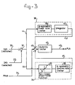
- FIG 3 for a description in detail of a preferred embodiment of the Approach Speed Control System.
- the Indicated Airspeed (30) and the Selected or Reference Airspeed(27) are compared in the summing point (32).
- the error signal (33) is delivered to a first and a second control circuit, (34) and (38).
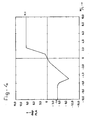
- the control circuits were designed after ample observation of the pilots manual response by moving the power lever, to deviations of the indicated airspeed from the selected airspeed. While shaping the diagram (see figure 4) the influence at the airspeed of the corrections by the autopilot of the approach trajectory was taken into account also.
- the first circuit comprises a non-linear proportional function (35) and an asymmetric dynamic rate limiter (36).
- the error signal (33) is transformed by the circuit (34) in a first PLA-adjustment input signal (37) of the summing point (45).
- the second control circuit (38) comprises an asymmetric fixed rate limiter (39) and a integrator (40).
- the rate limiter (39) makes that the rapidity by which a maximum PLA-correction is executed is limited, in order to obtain that a PLA-correction in the case of a too low airspeed is faster executed than the PLA-correction of the same value in the case of a too high airspeed.
- the first and the second control circuit, respectively (37) and (41), are added in the summing point (45).
- the third input signal (31) to the summing point (45) compensates the contribution of the component of the mass of the airplane in the direction of the speed of the airplane. During the descend trajectory the component of the airplane mass in the direction of the speed vector differs with the pitch attitude of the aircraft. For compensation the pitch angle (31) is deducted or added to the above mentioned speed error (33).
- the output signal (43) of the authority limiter (37) is supplied to the EEC (3) of each engine.
- the signals 37, 41 and 31 are summed in the junction (45) and the resulting signal is led to the authority limiter (42).
- the limiter (42) prevents that the Approach Speed Control System provides the EEC (3) a PLA-correction signal above for example +/-10 degrees.
Landscapes
- Engineering & Computer Science (AREA)
- Combustion & Propulsion (AREA)
- Chemical & Material Sciences (AREA)
- Automation & Control Theory (AREA)
- Physics & Mathematics (AREA)
- General Physics & Mathematics (AREA)
- Remote Sensing (AREA)
- Radar, Positioning & Navigation (AREA)
- Aviation & Aerospace Engineering (AREA)
- Mechanical Engineering (AREA)
- General Engineering & Computer Science (AREA)
- Combined Controls Of Internal Combustion Engines (AREA)
- Toys (AREA)
- Traffic Control Systems (AREA)
- Control Of Vehicle Engines Or Engines For Specific Uses (AREA)
Applications Claiming Priority (2)
| Application Number | Priority Date | Filing Date | Title |
|---|---|---|---|
| GB8925398 | 1989-11-10 | ||
| GB8925398A GB2237899B (en) | 1989-11-10 | 1989-11-10 | Automated approach speed control for an airplane |
Publications (2)
| Publication Number | Publication Date |
|---|---|
| EP0427345A2 true EP0427345A2 (fr) | 1991-05-15 |
| EP0427345A3 EP0427345A3 (en) | 1992-05-27 |
Family
ID=10666053
Family Applications (1)
| Application Number | Title | Priority Date | Filing Date |
|---|---|---|---|
| EP19900202937 Withdrawn EP0427345A3 (en) | 1989-11-10 | 1990-11-06 | Automated approach speed control for an airplane |
Country Status (4)
| Country | Link |
|---|---|
| US (1) | US5078345A (fr) |
| EP (1) | EP0427345A3 (fr) |
| CA (1) | CA2029558C (fr) |
| GB (1) | GB2237899B (fr) |
Cited By (2)
| Publication number | Priority date | Publication date | Assignee | Title |
|---|---|---|---|---|
| WO1993006354A1 (fr) * | 1991-09-17 | 1993-04-01 | Allied-Signal Inc. | Systeme de gestion de puissance pour moteurs a turbine |
| WO1993012331A1 (fr) * | 1991-12-09 | 1993-06-24 | United Technologies Corporation | Systeme de commande de turbomoteur a combustion |
Families Citing this family (14)
| Publication number | Priority date | Publication date | Assignee | Title |
|---|---|---|---|---|
| US5331559A (en) * | 1991-09-18 | 1994-07-19 | Alliedsignal Inc. | Apparatus for preventing propeller overshoot |
| US6450456B1 (en) * | 1999-12-20 | 2002-09-17 | Safe Flight Instrument Corporation | Airborne safe landing power control system and method |
| ATE280711T1 (de) * | 2001-09-15 | 2004-11-15 | Pilatus Flugzeugwerke Ag | Propellerflugzeug mit verbesserter stabilität um seine hochachse |
| US20060200279A1 (en) * | 2005-03-03 | 2006-09-07 | Ainsworth Robert J | Method of determining a comparison of an aircraft's performance capabilities with performance requirements |
| US9273614B2 (en) * | 2005-09-12 | 2016-03-01 | Industrial Turbine Company (Uk) Limited | Determination of a signal indicative of shaft power |
| US7774106B2 (en) * | 2006-12-22 | 2010-08-10 | Pratt - Whitney Canada Corp. | Cruise control FADEC logic |
| US7949440B2 (en) * | 2006-12-22 | 2011-05-24 | Embraer-Empresa Brasileira De Aeronautica S.A. | Aircraft cruise speed control |
| US8712607B2 (en) * | 2009-12-07 | 2014-04-29 | Sikorsky Aircraft Corporation | Systems and methods for velocity profile based approach to point control |
| WO2013123385A1 (fr) | 2012-02-15 | 2013-08-22 | Rolls-Royce Corporation | Commande de recherche de performance de moteur à turbine à gaz |
| CN106886223A (zh) * | 2015-12-15 | 2017-06-23 | 北京电研华源电力技术有限公司 | 一种风筝悬浮平台 |
| US10240544B2 (en) | 2016-10-27 | 2019-03-26 | Rolls-Royce Corporation | Adaptive controller using unmeasured operating parameter |
| US10309330B2 (en) | 2016-10-27 | 2019-06-04 | Rolls-Royce Corporation | Model reference adaptive controller |
| US10604268B2 (en) * | 2017-02-22 | 2020-03-31 | Pratt & Whitney Canada Corp. | Autothrottle control for turboprop engines |
| US11377223B2 (en) * | 2018-10-29 | 2022-07-05 | Pratt & Whitney Canada Corp. | Autothrottle control system on turbopropeller-powered aircraft |
Family Cites Families (19)
| Publication number | Priority date | Publication date | Assignee | Title |
|---|---|---|---|---|
| US2670157A (en) * | 1947-04-18 | 1954-02-23 | Bendix Aviat Corp | Engine control and synchronization system |
| US2553983A (en) * | 1947-08-09 | 1951-05-22 | Jr Edwin F Saxman | Automatic flight control and approach and landing system for aircraft |
| US2798682A (en) * | 1948-12-30 | 1957-07-09 | Honeywell Regulator Co | Aircraft control apparatus responsive to angle of attack |
| US3096955A (en) * | 1960-11-30 | 1963-07-09 | Elliott Brothers London Ltd | Automatic landing system for aircraft |
| US3456172A (en) * | 1965-08-18 | 1969-07-15 | Honeywell Inc | Automatic control apparatus for aircraft |
| DE1481548C3 (de) * | 1966-06-29 | 1975-04-17 | Bodenseewerk Geraetetechnik Gmbh, 7770 Ueberlingen | Vortriebsregler |
| DE1802217A1 (de) * | 1968-10-10 | 1970-05-14 | Bodensee Fluggeraete | Geschwindigkeitsregler fuer Flugzeuge |
| US3591110A (en) * | 1969-04-21 | 1971-07-06 | Lear Siegler Inc | Automatic throttle control system for an aircraft |
| US3614036A (en) * | 1969-10-13 | 1971-10-19 | Collins Radio Co | Conversion principle-angle of attack to airspeed |
| US3626163A (en) * | 1970-01-28 | 1971-12-07 | Us Army | Automatic landing system |
| US3691356A (en) * | 1970-12-10 | 1972-09-12 | Sperry Rand Corp | Speed command and throttle control system for aircraft |
| DE2127535B2 (de) * | 1971-06-03 | 1975-01-23 | Bodenseewerk Geraetetechnik Gmbh, 7770 Ueberlingen | Geschwindigkeitsregler für die Landeendgeschwindigkeit von Flugzeugen |
| GB1563501A (en) * | 1976-02-11 | 1980-03-26 | Elliott Bros | Aircrft instruments |
| US4044975A (en) * | 1976-05-17 | 1977-08-30 | Mcdonnell Douglas Corporation | Aircraft speed command system |
| US4209152A (en) * | 1977-11-25 | 1980-06-24 | The Boeing Company | Turbulence compensated throttle control system for aircraft having throttle command signal path control means responsive to engine rating control and flare initiation |
| US4245805A (en) * | 1977-11-25 | 1981-01-20 | The Boeing Company | Turbulence compensated throttle control system for aircraft having throttle command signal path control means responsive to engine rating control and flare initiation |
| US4357663A (en) * | 1979-12-03 | 1982-11-02 | The Boeing Company | Method and apparatus for aircraft pitch and thrust axes control |
| FR2532079A1 (fr) * | 1982-08-18 | 1984-02-24 | Sfena | Procede et dispositif de pilotage d'un aerodyne dans le plan vertical, permettant la capture et le maintien d'une vitesse selectee, puis la transition vers une capture d'altitude |
| US4958289A (en) * | 1988-12-14 | 1990-09-18 | General Electric Company | Aircraft propeller speed control |
-
1989
- 1989-11-10 GB GB8925398A patent/GB2237899B/en not_active Expired - Fee Related
-
1990
- 1990-11-06 EP EP19900202937 patent/EP0427345A3/en not_active Withdrawn
- 1990-11-08 CA CA002029558A patent/CA2029558C/fr not_active Expired - Fee Related
- 1990-11-08 US US07/610,518 patent/US5078345A/en not_active Expired - Fee Related
Cited By (2)
| Publication number | Priority date | Publication date | Assignee | Title |
|---|---|---|---|---|
| WO1993006354A1 (fr) * | 1991-09-17 | 1993-04-01 | Allied-Signal Inc. | Systeme de gestion de puissance pour moteurs a turbine |
| WO1993012331A1 (fr) * | 1991-12-09 | 1993-06-24 | United Technologies Corporation | Systeme de commande de turbomoteur a combustion |
Also Published As
| Publication number | Publication date |
|---|---|
| US5078345A (en) | 1992-01-07 |
| EP0427345A3 (en) | 1992-05-27 |
| CA2029558A1 (fr) | 1991-05-11 |
| GB8925398D0 (en) | 1989-12-28 |
| GB2237899B (en) | 1994-05-11 |
| CA2029558C (fr) | 1995-02-07 |
| GB2237899A (en) | 1991-05-15 |
Similar Documents
| Publication | Publication Date | Title |
|---|---|---|
| US5078345A (en) | Automated approach speed control for an airplane | |
| US5225829A (en) | Independent low airspeed alert | |
| US4924401A (en) | Aircraft ground collision avoidance and autorecovery systems device | |
| EP0028435B1 (fr) | Système de guidage d'avion en montée | |
| EP0601000B1 (fr) | Systeme de commande verticale pour aeronef a voilure tournante | |
| EP0743242B1 (fr) | Système de protection contre le décrochage pour autopilote/directeur de vol | |
| US4471439A (en) | Method and apparatus for aircraft pitch and thrust axes control | |
| US4319219A (en) | Automatic approach landing and go-around control system for aircraft | |
| EP1421334B1 (fr) | Systeme d'affichage d'altitude et de trajectoires de capture | |
| EP0093684B1 (fr) | Commande de moteur d'hélicoptère avec anticipateur de la décroissance de la vitesse du rotor | |
| EP2289799B1 (fr) | Contrôle de vitesse de croisière d'un avion | |
| EP0743243A1 (fr) | Système d'augmentation de la stabilité et de la manoeuvrabilité de l'axe de tangage pour aéronef | |
| US11054437B2 (en) | Method and system for aircraft sideslip guidance | |
| EP0030066B1 (fr) | Appareil de commande des axes d'inclinaison longitudinale et de poussée d'un avion | |
| US4797674A (en) | Flight guidance system for aircraft in windshear | |
| EP0115401A2 (fr) | Commande de vitesse pour un avion | |
| EP0394181A2 (fr) | Réglage de la survitesse de l'hélice au moyen des signaux numériques de l'angle d'incidence | |
| US6819266B2 (en) | System and method for reducing the speed of an aircraft | |
| EP0119723A2 (fr) | Système directeur de vol à trois indicateurs pour hélicoptères | |
| CA1234417A (fr) | Systeme avertissant le pilote de profils de vol dangereux au cours d'evolutions a basse altitude | |
| US7636617B2 (en) | Flight control indicator displaying the aircraft's thrust information | |
| US4563743A (en) | Maneuver-force gradient system | |
| US11975861B2 (en) | Retrofit aircraft autothrottle control for aircraft with engine controllers | |
| Hutto | Flight‐Test Report on the Heavy‐Lift Helicopter Flight‐Control System | |
| IL87382A (en) | Approach system for accurate landing of aircraft |
Legal Events
| Date | Code | Title | Description |
|---|---|---|---|
| PUAI | Public reference made under article 153(3) epc to a published international application that has entered the european phase |
Free format text: ORIGINAL CODE: 0009012 |
|
| 17P | Request for examination filed |
Effective date: 19901205 |
|
| AK | Designated contracting states |
Kind code of ref document: A2 Designated state(s): DE ES FR GB IT |
|
| PUAL | Search report despatched |
Free format text: ORIGINAL CODE: 0009013 |
|
| AK | Designated contracting states |
Kind code of ref document: A3 Designated state(s): DE ES FR GB IT |
|
| 17Q | First examination report despatched |
Effective date: 19940525 |
|
| GRAH | Despatch of communication of intention to grant a patent |
Free format text: ORIGINAL CODE: EPIDOS IGRA |
|
| STAA | Information on the status of an ep patent application or granted ep patent |
Free format text: STATUS: THE APPLICATION IS DEEMED TO BE WITHDRAWN |
|
| 18D | Application deemed to be withdrawn |
Effective date: 19960416 |