EP0427365A2 - Vorrichtung zur Lagerung und zum Ausgeben der Plastiktaschen - Google Patents
Vorrichtung zur Lagerung und zum Ausgeben der Plastiktaschen Download PDFInfo
- Publication number
- EP0427365A2 EP0427365A2 EP90300822A EP90300822A EP0427365A2 EP 0427365 A2 EP0427365 A2 EP 0427365A2 EP 90300822 A EP90300822 A EP 90300822A EP 90300822 A EP90300822 A EP 90300822A EP 0427365 A2 EP0427365 A2 EP 0427365A2
- Authority
- EP
- European Patent Office
- Prior art keywords
- slot portion
- tubular member
- dispensing
- storage
- bags
- Prior art date
- Legal status (The legal status is an assumption and is not a legal conclusion. Google has not performed a legal analysis and makes no representation as to the accuracy of the status listed.)
- Withdrawn
Links
- 229920003023 plastic Polymers 0.000 title description 4
- 229920002457 flexible plastic Polymers 0.000 claims abstract description 4
- 230000002093 peripheral effect Effects 0.000 claims description 3
- 238000000926 separation method Methods 0.000 description 4
- 230000000694 effects Effects 0.000 description 2
- 239000000463 material Substances 0.000 description 1
- 239000002184 metal Substances 0.000 description 1
Images

Classifications
-
- B—PERFORMING OPERATIONS; TRANSPORTING
- B65—CONVEYING; PACKING; STORING; HANDLING THIN OR FILAMENTARY MATERIAL
- B65B—MACHINES, APPARATUS OR DEVICES FOR, OR METHODS OF, PACKAGING ARTICLES OR MATERIALS; UNPACKING
- B65B43/00—Forming, feeding, opening or setting-up containers or receptacles in association with packaging
- B65B43/12—Feeding flexible bags or carton blanks in flat or collapsed state; Feeding flat bags connected to form a series or chain
- B65B43/14—Feeding individual bags or carton blanks from piles or magazines
-
- B—PERFORMING OPERATIONS; TRANSPORTING
- B65—CONVEYING; PACKING; STORING; HANDLING THIN OR FILAMENTARY MATERIAL
- B65H—HANDLING THIN OR FILAMENTARY MATERIAL, e.g. SHEETS, WEBS, CABLES
- B65H35/00—Delivering articles from cutting or line-perforating machines; Article or web delivery apparatus incorporating cutting or line-perforating devices, e.g. adhesive tape dispensers
- B65H35/0006—Article or web delivery apparatus incorporating cutting or line-perforating devices
- B65H35/0073—Details
- B65H35/008—Arrangements or adaptations of cutting devices
Definitions
- the present invention relates to a storage and dispensing apparatus for a cylindrical package of wound flexible plastic bags or the like, which are serially joined to each other along transverse severance lines.
- the leading edge of the initial bag on the package is manually threaded through the thread-up opening, and the leading edge is then grasped and moved laterally into the slot. Thereafter, the bags may be individually delivered by pulling the bags upwardly and laterally outwardly, and the zigzag slot exerts sufficient resistance so as to cause a severing of the leading bag from the immediately following bag along the perforated severance line.
- Copending and commonly owned U.S. Application Serial No. 07/331,962 discloses an improved dispensing nozzle of the described type, and wherein two circular thread-up openings are disposed at respective opposite ends of a zigzag dispensing slot.
- Copending and commonly owned U.S. Application Serial No. 07/349,289 discloses a similar bag dispensing apparatus which includes a rigid cylindrical tube having open opposite ends so as to be adapted to receive the rolled bag package coaxially therein, and with the tube having an elongate dispensing slot which extends along a minor portion of the length of the tube.
- the slot is of zigzag configuration, and its opposite ends are provided with enlarged access openings for permitting the leading bag of the package to be manually grasped to effect thread-up.
- a bag storage and dispensing apparatus which comprises a generally tubular member including a peripheral side wall having opposite ends, with at least one of the ends being open.
- An elongate slot extends through the side wall of the tubular member and the slot includes a dispensing slot portion extending along a medial portion of the length of the tubular member and a thread-up slot portion which extends from the dispensing slot portion into communication with the open end of the tubular member.
- the dispensing slot portion is of zigzag configuration along its length and is sized and configured for permitting the bags of the package to be serially withdrawn therethrough while resisting free movement of the bags therethrough. This resistance facilitates the severance of the withdrawn bag from the immediately following bag along the perforated severance line, and with the leading portion of the following bag positioned in the dispensing slot portion and ready for removal.
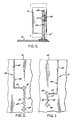
- Figure 1 illustrates a conventional grocery store checkout counter 10 which supports an apparatus 12 which is adapted to selectively dispense plastic bags in accordance with the present invention.
- the bags may be in the form of T-shirt or handle bags, with the bags being serially joined along transverse perforated severanced lines, and with the bags being supplied in a cylindrical wound package or roll.
- the apparatus 12 includes a supporting platform 14 which is adapted to be positioned on the upper surface of a checkout counter 10 or some other horizontal surface.
- a vertical post 15 is fixed to the platform 14, and a pair of tubular members 16 and 18 are mounted on the post 15 in the manner best seen in Figures 4 and 5.
- a bracket 20 is fixed to the outside of each tubular member, and the bracket is in turn mounted to the post 15 by threaded members 21.
- the post includes several vertically spaced apart openings 22 for the threaded members, so that the elevation of the tubular members with respect to the platform may be adjusted.
- Each tubular member 16, 18 comprises a cylindrical, peripheral side wall 24 which defines a longitudinal axis, which is disposed vertically when the supporting member is positioned on a horizontal surface.
- Each tubular member also includes a bottom wall 25 closing the lower end of the member, and an open upper end 26.
- the tubular members may be fabricated from any suitable rigid material such as metal or plastic, and they are adapted to coaxially receive wound packages P, P′ of bags of the described type.
- An elongate slot 30, 31 extends through the side wall 24 of each tubular member, 16, 18 respectively.
- the slot 30 includes a dispensing slot portion 32 which extends longitudinally along a medial portion of the length of the tubular member 16, and a thread-up slot portion 34 which extends from the upper end of the dispensing slot portion into communication with the open end of the associated tubular member.
- the dispensing slot portion 32 is of zigzag configuration along its length, and is sized and configured for permitting the bags of the package to be serially drawn therethrough, while resisting free movement of the bags therethrough.
- the dispensing slot portion 32 of the slot 30 defines opposing spaced apart edges 36, 37 of zigzag or sawtooth like configuration, and such that each edge comprises alternating V-shaped projections and recesses, and with the projections of each side edge being laterally aligned with the recesses of the opposite side edge.
- dispensing slot portion 32 includes a generally circular opening 38 at each longitudinal end thereof, with each of the openings 38 having a diameter greater than the lateral distance between the recesses on opposite side edges of the associated slot.
- the thread-up slot portion 34 is of generally L-shaped configuration, and it includes an axial segment 40 which communicates with the open end 26 of the tubular member 16, and a transverse segment 41 which communicates with the upper one of the openings 38. Each of the segments 40, 41 comprises straight side edges which are uniformly spaced from each other, as opposed to the zigzag configuration of the dispensing slot portion.
- the free end of the leading bag of a package of bags P may be threaded through the dispensing slot portion 32 by manually sliding the free end along the thread-up slot portion 34 and into the dispensing slot portion 32.
- the bags may then be serially dispensed, by drawing the leading bag laterally outwardly from the dispensing slot portion, and as the bag moves outwardly, the resistance imparted by the engagement of the projections of the slot portion with the moving bag resists the free movement of the bag. This resistance facilitates the severance of the withdrawn bag from the immediately following bag joined thereto along the severance line.
- the slot 31 of the tubular member 18 is of similar configuration, and it includes a dispensing slot portion 42 and a thread-up slot portion 44.
- the dispensing slot portion 42 is a zigzag configuration and includes opposing, spaced apart side edges 46, 47 composed of V-shaped projections and recesses, and a generally circular opening 48 at each longitudinal end thereof.
- the thread-up slot portion 44 includes an axial segment 50 and a transverse segment 51 which communicates with the upper opening 48.
- the dispensing slot portion 42 of the tubular member 18 is longitudinally shorter than the dispensing slot portion 32 of the tubular member 16, and the separation of the edges 46, 47 of the slot portion 42 is somewhat less than the separation of the edges 36, 37 of the slot portion 32.
- the two tubular members 16, 18 are adapted to accommodate and dispense bags of different width, as indicated by the different lengths of the packages P, P′ as seen in the drawings.
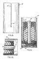
- Figures 8 and 9 illustrate an embodiment of the present invention which comprises a single cylindrical tubular member 54 which is adapted to be positioned directly upon the countertop surface, with the axis of the tubular member extending vertically.
- the tubular member may be disposed in a different orientation, such as horizontally, by means of a suitable supporting means (not shown).
- the lower internal periphery of the cylindrical tubular member is internally threaded as indicated at 55, and the transverse bottom wall comprises a disc 56 having external threads which engage the threads 55 of the tubular member.
- a package supporting post 58 is fixed to the bottom wall 56 and extends coaxially along the interior of the tubular member.
- the post 58 and the bottom wall 56 may be rotated with respect to the tubular member, so as to adjust the longitudinal position of the bottom wall within the tubular member, and thereby permit the tubular member to be adapted to receive tubular bag packages of varying length, with the packages being coaxially received on the post 58 and longitudinally centered with the dispensing slot portion 60.
- the upper end of the post 58 includes an integral enlarged end cap 59.
- the end cap 59 acts to engage the end of the package of bags P when the tubular member is oriented horizontally, and so as to prevent the axial separation of the package from the post.
- the diameter of the end cap 59 is preferably slightly less than the internal diameter of the tubular package so as to permit the package to be slipped onto the post 58, and when the tubular member is turned horizontally as seen in Figure 10, the package drops down so that its end engages the end cap.
- the dispensing slot portion 60 may be defined as the lower portion of a continuous longitudinal slot and through which the bags are normally dispensed, and the dispensing slot portion 60 is of the same or similar sawtooth like configuration as described above with respect to the embodiment of Figures 1-7.
- the thread-up slot portion 61 continues in the same longitudinal direction from the dispensing slot portion, and it has spaced apart side edges along its length which are of a sawtooth like configuration which conforms to the configuration of the dispensing slot portion.
- a dispensing slot portion 60 and the thread-up slot portion 61 present a continuous slot of zigzag configuration.
- dispensing slot portion should be of generally zig-zag configuration it is not necessary for both opposing edges defining said slot portion to be of sawtooth configuration. It is sufficient that one of said defining edges has alternate projections and recesses, as this can still suffice to frictionally engage the bags as they are withdrawn therethrough.
Landscapes
- Engineering & Computer Science (AREA)
- Mechanical Engineering (AREA)
- Containers And Packaging Bodies Having A Special Means To Remove Contents (AREA)
Applications Claiming Priority (2)
| Application Number | Priority Date | Filing Date | Title |
|---|---|---|---|
| US433502 | 1982-10-08 | ||
| US43350289A | 1989-11-08 | 1989-11-08 |
Publications (2)
| Publication Number | Publication Date |
|---|---|
| EP0427365A2 true EP0427365A2 (de) | 1991-05-15 |
| EP0427365A3 EP0427365A3 (en) | 1991-07-17 |
Family
ID=23720362
Family Applications (1)
| Application Number | Title | Priority Date | Filing Date |
|---|---|---|---|
| EP19900300822 Withdrawn EP0427365A3 (en) | 1989-11-08 | 1990-01-26 | Storage and dispensing apparatus for plastic bags |
Country Status (4)
| Country | Link |
|---|---|
| EP (1) | EP0427365A3 (de) |
| CA (1) | CA2012378A1 (de) |
| FI (1) | FI901493A7 (de) |
| NO (1) | NO901115L (de) |
Cited By (1)
| Publication number | Priority date | Publication date | Assignee | Title |
|---|---|---|---|---|
| US6056179A (en) * | 1994-11-11 | 2000-05-02 | Muzquiz; Federico De Hoyos | Single bag dispenser rollholder |
Family Cites Families (1)
| Publication number | Priority date | Publication date | Assignee | Title |
|---|---|---|---|---|
| US4793539A (en) * | 1987-04-07 | 1988-12-27 | Sonoco Products Company | Through-counter dispensing system for plastic bags |
-
1990
- 1990-01-26 EP EP19900300822 patent/EP0427365A3/en not_active Withdrawn
- 1990-03-09 NO NO90901115A patent/NO901115L/no unknown
- 1990-03-16 CA CA002012378A patent/CA2012378A1/en not_active Abandoned
- 1990-03-26 FI FI901493A patent/FI901493A7/fi not_active Application Discontinuation
Cited By (1)
| Publication number | Priority date | Publication date | Assignee | Title |
|---|---|---|---|---|
| US6056179A (en) * | 1994-11-11 | 2000-05-02 | Muzquiz; Federico De Hoyos | Single bag dispenser rollholder |
Also Published As
| Publication number | Publication date |
|---|---|
| NO901115D0 (no) | 1990-03-09 |
| FI901493A0 (fi) | 1990-03-26 |
| FI901493A7 (fi) | 1991-05-09 |
| EP0427365A3 (en) | 1991-07-17 |
| CA2012378A1 (en) | 1991-05-08 |
| NO901115L (no) | 1991-05-10 |
Similar Documents
| Publication | Publication Date | Title |
|---|---|---|
| US4930385A (en) | Dispensing nozzle for plastic bags | |
| US7424963B2 (en) | Roll mounted bags and dispensers for same | |
| US5219424A (en) | Roll of plastic bags for use with bag dispensing device | |
| CA1331747C (en) | Tube dispenser for flexible sheet material | |
| AU669452B2 (en) | Plastic bag dispenser and bags therefor | |
| US5573168A (en) | Dispenser for plastic bags | |
| CA2075853C (en) | Dispensing apparatus for plastic bags | |
| CA2060708C (en) | Plastic bag dispenser | |
| US5752666A (en) | Plastic bag roll | |
| EP0401950B1 (de) | Einrichtung zum automatischen Öffnen und anschliessenden Abgeben von Verkaufsbeuteln | |
| US5727721A (en) | Flexible web dispenser | |
| EP0772562B1 (de) | Beuteltrennvorrichtung und -spender | |
| AU708790B2 (en) | Bag separator and dispenser | |
| US7591405B2 (en) | Roll mounted bags and dispensers for same | |
| CA2092068C (en) | Method and apparatus for dispensing t-shirt style merchandise bags | |
| US5813585A (en) | Dispenser for plastic bags | |
| US5125604A (en) | System for automatic consecutive opening and dispensing thermoplastic grocery or retail product bags | |
| US4179055A (en) | Device for separating sheet bags | |
| US5242495A (en) | Combined joint compound bucket and tape dispenser | |
| US20020185513A1 (en) | Bag separator and dispenser | |
| US4979617A (en) | Dispensing system for severable sheet material | |
| US6585197B1 (en) | Produce bags and dispensers for same providing easy open features | |
| EP0427365A2 (de) | Vorrichtung zur Lagerung und zum Ausgeben der Plastiktaschen | |
| EP0569641A1 (de) | Abgabevorrichtung für Plastiktüten | |
| EP0778810B1 (de) | Spender für kunststoffbeutel |
Legal Events
| Date | Code | Title | Description |
|---|---|---|---|
| PUAI | Public reference made under article 153(3) epc to a published international application that has entered the european phase |
Free format text: ORIGINAL CODE: 0009012 |
|
| AK | Designated contracting states |
Kind code of ref document: A2 Designated state(s): AT BE CH DE DK ES FR GB GR IT LI LU NL SE |
|
| PUAL | Search report despatched |
Free format text: ORIGINAL CODE: 0009013 |
|
| AK | Designated contracting states |
Kind code of ref document: A3 Designated state(s): AT BE CH DE DK ES FR GB GR IT LI LU NL SE |
|
| STAA | Information on the status of an ep patent application or granted ep patent |
Free format text: STATUS: THE APPLICATION IS DEEMED TO BE WITHDRAWN |
|
| 18D | Application deemed to be withdrawn |
Effective date: 19920118 |