EP0427630A1 - Abgeschirmter elektrischer Verbinder - Google Patents
Abgeschirmter elektrischer Verbinder Download PDFInfo
- Publication number
- EP0427630A1 EP0427630A1 EP90403168A EP90403168A EP0427630A1 EP 0427630 A1 EP0427630 A1 EP 0427630A1 EP 90403168 A EP90403168 A EP 90403168A EP 90403168 A EP90403168 A EP 90403168A EP 0427630 A1 EP0427630 A1 EP 0427630A1
- Authority
- EP
- European Patent Office
- Prior art keywords
- shielding
- shell
- connector element
- shells
- side wall
- Prior art date
- Legal status (The legal status is an assumption and is not a legal conclusion. Google has not performed a legal analysis and makes no representation as to the accuracy of the status listed.)
- Granted
Links
- 239000002184 metal Substances 0.000 claims abstract description 17
- 230000000295 complement effect Effects 0.000 claims abstract description 7
- 230000002093 peripheral effect Effects 0.000 claims description 9
- 230000002787 reinforcement Effects 0.000 claims description 7
- 238000005192 partition Methods 0.000 claims description 2
- 230000000694 effects Effects 0.000 description 4
- 230000015556 catabolic process Effects 0.000 description 2
- 238000002788 crimping Methods 0.000 description 2
- 238000003780 insertion Methods 0.000 description 2
- 230000037431 insertion Effects 0.000 description 2
- 239000000463 material Substances 0.000 description 2
- 239000003566 sealing material Substances 0.000 description 2
- 239000011810 insulating material Substances 0.000 description 1
- 230000004048 modification Effects 0.000 description 1
- 238000012986 modification Methods 0.000 description 1
- 238000000465 moulding Methods 0.000 description 1
- 230000035515 penetration Effects 0.000 description 1
- 125000006850 spacer group Chemical group 0.000 description 1
- 238000005482 strain hardening Methods 0.000 description 1
Images



Classifications
-
- H—ELECTRICITY
- H01—ELECTRIC ELEMENTS
- H01R—ELECTRICALLY-CONDUCTIVE CONNECTIONS; STRUCTURAL ASSOCIATIONS OF A PLURALITY OF MUTUALLY-INSULATED ELECTRICAL CONNECTING ELEMENTS; COUPLING DEVICES; CURRENT COLLECTORS
- H01R13/00—Details of coupling devices of the kinds covered by groups H01R12/70 or H01R24/00 - H01R33/00
- H01R13/648—Protective earth or shield arrangements on coupling devices, e.g. anti-static shielding
- H01R13/658—High frequency shielding arrangements, e.g. against EMI [Electro-Magnetic Interference] or EMP [Electro-Magnetic Pulse]
- H01R13/6581—Shield structure
Definitions
- the present invention relates to a shielded electrical connector element of the type comprising an insulating connector block comprising several cells in which electrical contact elements are received and which extends from its front face towards the rear of the connector element to the inside of a shielding box made up of two metallic shielding shells, respectively upper and lower, of complementary shapes to surround the insulating block and the free front edges of which include lugs in notches formed in the storyteller d '' a rear metal connector shell which surrounds and cooperates with an edge projecting outwards from the front part of the insulating block, the upper and lower shielding shells each comprising a side wall which are parallel and turned towards one another 'other.
- the rear metal shell of the connector which surrounds the front face of the insulating block and which is designed to allow it to be fixed for example on a mounting plate and the connection to a complementary connector element , has been modified, and in particular has an increased thickness, to allow the attachment of the fixing lugs.
- the rear shells are no longer of standardized dimensions which allow standard mounting in panel openings, for example of a "rack" comprising standardized openings provided for receiving connectors of the corresponding series.
- the contacting pressure of the two shells against the contour of the shell is provided by a spacer effect of the insulating block between the shells, which deforms the insulating block.
- this type of connector is designed to receive a hot overmolded layer of plastic to make it moisture-proof.
- a very strong pressure is applied on the upper and lower shells which has the consequence of causing a partial crushing of the insulating block. If vents are provided to avoid the crushing phenomenon, the hot overmolding material penetrates inside the connector and can cause the insulating sheaths of the electric wires connected to the electrical contact elements to melt and the insulating material flows. can deform the walls.
- the shielding box has only a very low mechanical resistance both lateral and vertical.
- the object of the present invention is to propose an electrical connector element whose various characteristics make it possible to remedy the drawbacks which have just been mentioned.
- the two side walls of the lower and upper shells are fitted one into the other;
- the side wall of the lower shielding shell has a peripheral recess directed towards the inside of the housing which delimits a bearing edge of the free peripheral edge of the side wall of the upper shell;
- the side wall of the lower shielding shell extends beyond said recess parallel to itself in the direction of the flat bottom of the upper shielding shell and the free peripheral edge of this side wall is in abutment against the flat bottom the upper armor shell;
- each of the two shielding shells has a flat bottom which bears against a corresponding face of the insulating block delimited by the edges of the partitions delimiting said cells which receive the electrical contact elements, and each flat bottom comprises a reinforcement boss projecting towards the outside of the shielding box and parallel to the free front edge of the shell;
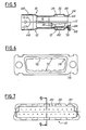
- FIGs 1 to 5 there is shown in Figures 1 to 5 an upper shielding shell 10 and a lower shielding shell 12 provided to be associated to form a shielding housing of an electrical connector element comprising in particular an insulating block 14 intended to receive elements of electrical contact 16 arranged in cells 18 of the insulating block (see Figure 10).
- the upper shell 10 essentially consists of a flat bottom 20 of substantially rectangular shape, the front free edge 22 of which is provided with five hooking tabs 24.
- the other edges of the flat bottom 20 extend at right angles, towards the bottom considering FIG. 1, by a peripheral lateral wall 26.
- the upper shell of shielding 10 comprises a semi-cylindrical portion 28 intended to receive the electrical wires 30 connected to the electrical contact elements 16 and the shielding braid on the outside.
- the flat bottom 20 comprises a reinforcement boss 32 which projects outwards from the shielding shell, which is of substantially rectangular shape and whose length is parallel to the free front edge 22.
- the boss 32 is arranged (see FIG. 5) in the region of the insulating block 14 which receives the uppermost portions of the electrical contact elements 16, this so as to create a large space between the internal face 34 of the reinforcement boss 32 and the electrical contact elements 16 to avoid any phenomenon of electrical breakdown.
- the two rearward-facing portions of the side wall 26 each have an opening 36 provided for receiving a latch for locking the shielding box.
- a flat bottom 38 delimited by its front edge 40, its side wall 42, its rear semi-cylindrical portion 44, and comprising a reinforcement boss projecting outwards. 46. It also has five hooking lugs 48.
- the side wall 42 of the lower shielding shell 12 has a first portion 50 substantially symmetrical with the side wall 26 which is delimited by a peripheral recess 52 beyond which it is extended by a second portion of side wall 54 which is parallel to the first part 50 but offset towards the inside so as to allow it to fit inside the side wall 26.
- the second part 54 has in its two portions rear of the locking pins 56 intended to be received in the openings 36.
- the two semi-cylindrical portions 28 and 44 receive, after assembly of the connector, a closing ring 58 before the final crimping operation.
- Each of the two shielding shells is produced by stamping a sheet metal.
- reinforcement bosses 32 and 46 are rigid enough to transmit the forces which will be applied to them during the final overmolding operation of a plastic sealing material to the side walls.
- peripheral end edge 62 of the side wall 26 bears against the recess 52 of the side wall 42 of the lower shielding shell 12.
- This double bearing effect allows the forces transmitted to the side walls to be absorbed during overmolding and to ensure perfect electrical continuity and optimal shielding.
- the arrangement in the nested position of the two shielding shells 10 and 12 therefore provides, on the one hand, very good electrical shielding to the stray fields due to the superposition of the side wall 26 with the second portion of, side wall 54 and, on the other hand, very good electrical contact by the bearing edges.
- the inner faces of the flat bottoms 20 and 38 surround the insulating block 14, as can be seen in FIG. 5, but without applying any force to it.
- each latch 24 or 48 has a particular profile. This profile will be described with reference to the lower lug 48 shown in FIG. 5.
- the tab 38 has an L-shaped profile.
- a first branch 66 extends horizontally from the free front edge 40 of the lower shell 12 and extends towards the outside of the housing by a second branch at right angles 68.
- the first branch 66 is of reduced thickness compared to that of the sheet metal constituting the shell, as is the second branch 68 whose thickness is equal to that of the first branch. This reduction in thickness is obtained during the cutting-stamping operation of the shell by crushing the sheet, which causes a phenomenon of work hardening which notably increases the resistance characteristics of the sheet in the area of the latching tabs. .
- the first branch 66 in cooperation with the second branch 68, and because of its reduced thickness, constitutes a U-shaped notch which is designed to receive the edge 70 opposite a corresponding notch 72 formed in the contour 74 of the rear standardized metal shell 76 of the connector element (see FIG. 6).
- the free edge of the second branch 68 cooperates with a curved region of the sheet metal of the rear shell 76, which gives an effect of wedging and retaining the edge 70 in the U-shaped notch.
- the assembled housing itself forms a very rigid and homogeneous shell as soon as it is assembled, regardless of the presence of an overmolding.
- each of the hooking lugs is received in a recess 80 formed in the face 82 facing the rear of the front part 84 of the insulating block 14 and away from the front face 17 of the latter.
- the insulating block 14 naturally includes, on either side of its longitudinal median plane, a number of recesses 80 equal to those of the legs 24 and 48.
- the recesses 80 facilitate the insertion of the hooking lugs during the assembly of the upper and lower shielding shells on the sub-assembly shown. in FIG. 10, this assembly being carried out in a conventional manner by introduction of the hooking lugs in the holes 82 delimited by the recesses 80 and the notches 72 then by pivoting of the shells around the hooking lugs until they are brought into the position shown in Figures 4 and 5.
- the hooking lugs being arranged symmetrically in pairs in one and the other, the two shielding shells 10 and 12 can optionally be produced using the same starting tool on which it it suffices to add a punch to eliminate the portion of sheet metal corresponding to the second part 54 of the side wall 50 as well as two punches for cutting the holes 36.
- the symmetrical design of the shells 10 and 12 allows indifferent mounting in place of one another, the lower and upper terminology being used only for writing convenience.
- This indifferent mounting is particularly advantageous in the case where the shells have bent rear cable outlets relative to their direction of insertion, since the same set of two complementary shells makes it possible to produce a bend on the left or a bend on the right.
- the shell formed by the shielding shells and the rear shell is very homogeneous and resistant, both laterally due to the cooperation of the side walls, and vertically due to the edges pressing against the bottoms and the recess, and only longitudinally due to the notches received in the U-shaped notches of the hanging tabs.
Landscapes
- Details Of Connecting Devices For Male And Female Coupling (AREA)
Applications Claiming Priority (2)
| Application Number | Priority Date | Filing Date | Title |
|---|---|---|---|
| FR8914802A FR2654558B1 (fr) | 1989-11-10 | 1989-11-10 | Element de connecteur electrique blinde. |
| FR8914802 | 1989-11-10 |
Publications (2)
| Publication Number | Publication Date |
|---|---|
| EP0427630A1 true EP0427630A1 (de) | 1991-05-15 |
| EP0427630B1 EP0427630B1 (de) | 1995-07-19 |
Family
ID=9387302
Family Applications (1)
| Application Number | Title | Priority Date | Filing Date |
|---|---|---|---|
| EP19900403168 Expired - Lifetime EP0427630B1 (de) | 1989-11-10 | 1990-11-07 | Abgeschirmter elektrischer Verbinder |
Country Status (3)
| Country | Link |
|---|---|
| EP (1) | EP0427630B1 (de) |
| DE (1) | DE69021012T2 (de) |
| FR (1) | FR2654558B1 (de) |
Cited By (5)
| Publication number | Priority date | Publication date | Assignee | Title |
|---|---|---|---|---|
| GB2257577A (en) * | 1991-06-26 | 1993-01-13 | Hosiden Corp | Shielded electrical connector. |
| EP0530076A1 (de) * | 1991-08-27 | 1993-03-03 | Framatome Connectors France | Abgeschirmter elektrischer Verbinder |
| WO1998036475A1 (en) * | 1997-02-18 | 1998-08-20 | The Whitaker Corporation | Panel mounting structure |
| EP2178177A4 (de) * | 2007-08-01 | 2012-04-04 | Autonetworks Technologies Ltd | Abgeschirmter steckverbinder |
| US10498088B2 (en) | 2014-04-01 | 2019-12-03 | CommScope Connectivity Spain, S.L. | Shielded telecommunications connector |
Families Citing this family (1)
| Publication number | Priority date | Publication date | Assignee | Title |
|---|---|---|---|---|
| JP3803837B2 (ja) * | 1997-02-21 | 2006-08-02 | モレックス インコーポレーテッド | 電気コネクタおよび金属シェル |
Citations (5)
| Publication number | Priority date | Publication date | Assignee | Title |
|---|---|---|---|---|
| EP0090539A2 (de) * | 1982-03-31 | 1983-10-05 | AMP INCORPORATED (a New Jersey corporation) | Abgeschirmter Verbinder |
| WO1985005230A1 (en) * | 1984-05-04 | 1985-11-21 | Amp Incorporated | Overmolded shielded connector |
| DE8625668U1 (de) * | 1986-09-25 | 1986-11-20 | DSG Schrumpfschlauch GmbH, 5309 Meckenheim | Steckverbinderendgehäuse für abgeschirmte elektrische Kabelanschlüsse |
| US4653836A (en) * | 1983-07-06 | 1987-03-31 | Amp Incorporated | Shielded electrical connector |
| US4689723A (en) * | 1986-09-29 | 1987-08-25 | Amp Incorporated | Hermaphroditic shield for line terminator |
-
1989
- 1989-11-10 FR FR8914802A patent/FR2654558B1/fr not_active Expired - Fee Related
-
1990
- 1990-11-07 DE DE1990621012 patent/DE69021012T2/de not_active Expired - Fee Related
- 1990-11-07 EP EP19900403168 patent/EP0427630B1/de not_active Expired - Lifetime
Patent Citations (5)
| Publication number | Priority date | Publication date | Assignee | Title |
|---|---|---|---|---|
| EP0090539A2 (de) * | 1982-03-31 | 1983-10-05 | AMP INCORPORATED (a New Jersey corporation) | Abgeschirmter Verbinder |
| US4653836A (en) * | 1983-07-06 | 1987-03-31 | Amp Incorporated | Shielded electrical connector |
| WO1985005230A1 (en) * | 1984-05-04 | 1985-11-21 | Amp Incorporated | Overmolded shielded connector |
| DE8625668U1 (de) * | 1986-09-25 | 1986-11-20 | DSG Schrumpfschlauch GmbH, 5309 Meckenheim | Steckverbinderendgehäuse für abgeschirmte elektrische Kabelanschlüsse |
| US4689723A (en) * | 1986-09-29 | 1987-08-25 | Amp Incorporated | Hermaphroditic shield for line terminator |
Cited By (11)
| Publication number | Priority date | Publication date | Assignee | Title |
|---|---|---|---|---|
| GB2257577A (en) * | 1991-06-26 | 1993-01-13 | Hosiden Corp | Shielded electrical connector. |
| GB2257577B (en) * | 1991-06-26 | 1995-08-30 | Hosiden Corp | Electrical connector |
| EP0530076A1 (de) * | 1991-08-27 | 1993-03-03 | Framatome Connectors France | Abgeschirmter elektrischer Verbinder |
| FR2680916A1 (fr) * | 1991-08-27 | 1993-03-05 | Souriau & Cie | Connecteur electrique blinde. |
| US5319156A (en) * | 1991-08-27 | 1994-06-07 | Souriau Et Cie | Shielded electrical connector |
| WO1998036475A1 (en) * | 1997-02-18 | 1998-08-20 | The Whitaker Corporation | Panel mounting structure |
| EP2178177A4 (de) * | 2007-08-01 | 2012-04-04 | Autonetworks Technologies Ltd | Abgeschirmter steckverbinder |
| US10498088B2 (en) | 2014-04-01 | 2019-12-03 | CommScope Connectivity Spain, S.L. | Shielded telecommunications connector |
| EP3127189B1 (de) * | 2014-04-01 | 2021-01-27 | CommScope Connectivity Spain, S.L. | Abgeschirmter telekommunikationsverbinder |
| US10958018B2 (en) | 2014-04-01 | 2021-03-23 | CommScope Connectivity Spain, S.L. | Shielded telecommunications connector |
| US11476622B2 (en) | 2014-04-01 | 2022-10-18 | CommScope Connectivity Spain, S.L. | Shielded telecommunications connector |
Also Published As
| Publication number | Publication date |
|---|---|
| FR2654558B1 (fr) | 1993-12-17 |
| EP0427630B1 (de) | 1995-07-19 |
| DE69021012T2 (de) | 1995-12-14 |
| FR2654558A1 (fr) | 1991-05-17 |
| DE69021012D1 (de) | 1995-08-24 |
Similar Documents
| Publication | Publication Date | Title |
|---|---|---|
| EP0521751B1 (de) | Vorrichtung zur Herstellung von Abzweigungen von geschirmten Kabeln | |
| EP2315315B1 (de) | Koaxialer sockel | |
| BE1000101A6 (fr) | Connecteurs electriques. | |
| FR2763434A1 (fr) | Connecteur electrique blinde | |
| FR2720197A1 (fr) | Connecteur pour câble électrique. | |
| EP3687003B1 (de) | Steckverbinder für gedruckte schaltung, der mit einer leitenden hülle zum verschliessen einer übertragungsleitung für elektrische signale ausgestattet ist | |
| FR2787642A1 (fr) | Assemblage de connecteurs electriques | |
| FR2684242A1 (fr) | Assemblage de connecteur electrique comportant un element de verrouillage des bornes. | |
| FR3044172A1 (fr) | Contact electrique femelle avec patte de guidage du linguet et procede de fabrication d'un tel contact | |
| EP2466692B1 (de) | Steckverbinder für Leiterplatte | |
| FR3028357A1 (fr) | Connecteur electrique et procede de fabrication de celui-ci | |
| FR2680434A1 (fr) | Joint d'etancheite, notamment d'etancheite electromagnetique. | |
| EP0427630B1 (de) | Abgeschirmter elektrischer Verbinder | |
| EP2891178B1 (de) | Körper zum pressen eines teils auf eine oberfläche | |
| EP1590862B1 (de) | Elektrischer verbinder | |
| EP0673084B1 (de) | Gehäuseteil eines elektrischen Verbinders | |
| EP3477789B1 (de) | Adapter für abgeschirmten steckverbinder, abgeschirmter steckverbinder und montageverfahren eines solchen abgeschirmten steckverbinders | |
| EP0660447B1 (de) | Verbesserungen an Gehäuseteilen von elektrischen Verbindern | |
| FR2613532A1 (fr) | Fusible plat | |
| EP0530076B1 (de) | Abgeschirmter elektrischer Verbinder | |
| WO2015071172A1 (fr) | Connecteur electrique a reprise de blindage | |
| EP0147332A2 (de) | Elektrischer Verbinder | |
| EP0518739A1 (de) | Stecker für elektrische Verbindungen | |
| FR2579026A2 (fr) | Dispositif de raccord pour une embase d'antenne destinee a etre fixee sur une paroi et capuchon d'antiparasitage pour un tel dispositif | |
| JP3680767B2 (ja) | フラットケーブル用コネクタ |
Legal Events
| Date | Code | Title | Description |
|---|---|---|---|
| PUAI | Public reference made under article 153(3) epc to a published international application that has entered the european phase |
Free format text: ORIGINAL CODE: 0009012 |
|
| AK | Designated contracting states |
Kind code of ref document: A1 Designated state(s): DE GB IT |
|
| 17P | Request for examination filed |
Effective date: 19911024 |
|
| 17Q | First examination report despatched |
Effective date: 19931229 |
|
| GRAA | (expected) grant |
Free format text: ORIGINAL CODE: 0009210 |
|
| AK | Designated contracting states |
Kind code of ref document: B1 Designated state(s): DE GB IT |
|
| REF | Corresponds to: |
Ref document number: 69021012 Country of ref document: DE Date of ref document: 19950824 |
|
| GBT | Gb: translation of ep patent filed (gb section 77(6)(a)/1977) |
Effective date: 19950822 |
|
| ITF | It: translation for a ep patent filed | ||
| PLBE | No opposition filed within time limit |
Free format text: ORIGINAL CODE: 0009261 |
|
| STAA | Information on the status of an ep patent application or granted ep patent |
Free format text: STATUS: NO OPPOSITION FILED WITHIN TIME LIMIT |
|
| 26N | No opposition filed | ||
| REG | Reference to a national code |
Ref country code: GB Ref legal event code: IF02 |
|
| PGFP | Annual fee paid to national office [announced via postgrant information from national office to epo] |
Ref country code: GB Payment date: 20041103 Year of fee payment: 15 |
|
| PGFP | Annual fee paid to national office [announced via postgrant information from national office to epo] |
Ref country code: DE Payment date: 20041230 Year of fee payment: 15 |
|
| PG25 | Lapsed in a contracting state [announced via postgrant information from national office to epo] |
Ref country code: IT Free format text: LAPSE BECAUSE OF NON-PAYMENT OF DUE FEES;WARNING: LAPSES OF ITALIAN PATENTS WITH EFFECTIVE DATE BEFORE 2007 MAY HAVE OCCURRED AT ANY TIME BEFORE 2007. THE CORRECT EFFECTIVE DATE MAY BE DIFFERENT FROM THE ONE RECORDED. Effective date: 20051107 Ref country code: GB Free format text: LAPSE BECAUSE OF NON-PAYMENT OF DUE FEES Effective date: 20051107 |
|
| PG25 | Lapsed in a contracting state [announced via postgrant information from national office to epo] |
Ref country code: DE Free format text: LAPSE BECAUSE OF NON-PAYMENT OF DUE FEES Effective date: 20060601 |
|
| GBPC | Gb: european patent ceased through non-payment of renewal fee |
Effective date: 20051107 |