EP0427748B1 - Vorrichtung zum verbinden von zwei materialbahnen - Google Patents
Vorrichtung zum verbinden von zwei materialbahnen Download PDFInfo
- Publication number
- EP0427748B1 EP0427748B1 EP89908524A EP89908524A EP0427748B1 EP 0427748 B1 EP0427748 B1 EP 0427748B1 EP 89908524 A EP89908524 A EP 89908524A EP 89908524 A EP89908524 A EP 89908524A EP 0427748 B1 EP0427748 B1 EP 0427748B1
- Authority
- EP
- European Patent Office
- Prior art keywords
- web
- pressure
- bar
- frame
- cutting
- Prior art date
- Legal status (The legal status is an assumption and is not a legal conclusion. Google has not performed a legal analysis and makes no representation as to the accuracy of the status listed.)
- Expired - Lifetime
Links
- 239000000463 material Substances 0.000 title claims abstract description 51
- 238000005520 cutting process Methods 0.000 claims abstract description 48
- 238000011144 upstream manufacturing Methods 0.000 claims description 3
- 238000002360 preparation method Methods 0.000 claims description 2
- 208000027418 Wounds and injury Diseases 0.000 description 2
- 239000000853 adhesive Substances 0.000 description 2
- 230000001070 adhesive effect Effects 0.000 description 2
- 230000006378 damage Effects 0.000 description 2
- 230000005484 gravity Effects 0.000 description 2
- 208000014674 injury Diseases 0.000 description 2
- 230000007935 neutral effect Effects 0.000 description 2
- 239000000725 suspension Substances 0.000 description 2
- 230000000694 effects Effects 0.000 description 1
- 238000004519 manufacturing process Methods 0.000 description 1
- 238000000034 method Methods 0.000 description 1
- 238000003825 pressing Methods 0.000 description 1
Images

Classifications
-
- B—PERFORMING OPERATIONS; TRANSPORTING
- B65—CONVEYING; PACKING; STORING; HANDLING THIN OR FILAMENTARY MATERIAL
- B65H—HANDLING THIN OR FILAMENTARY MATERIAL, e.g. SHEETS, WEBS, CABLES
- B65H19/00—Changing the web roll
- B65H19/10—Changing the web roll in unwinding mechanisms or in connection with unwinding operations
- B65H19/18—Attaching, e.g. pasting, the replacement web to the expiring web
- B65H19/1857—Support arrangement of web rolls
- B65H19/1873—Support arrangement of web rolls with two stationary roll supports carrying alternately the replacement and the expiring roll
-
- B—PERFORMING OPERATIONS; TRANSPORTING
- B65—CONVEYING; PACKING; STORING; HANDLING THIN OR FILAMENTARY MATERIAL
- B65H—HANDLING THIN OR FILAMENTARY MATERIAL, e.g. SHEETS, WEBS, CABLES
- B65H19/00—Changing the web roll
- B65H19/10—Changing the web roll in unwinding mechanisms or in connection with unwinding operations
- B65H19/18—Attaching, e.g. pasting, the replacement web to the expiring web
- B65H19/1842—Attaching, e.g. pasting, the replacement web to the expiring web standing splicing, i.e. the expiring web being stationary during splicing contact
- B65H19/1852—Attaching, e.g. pasting, the replacement web to the expiring web standing splicing, i.e. the expiring web being stationary during splicing contact taking place at a distance from the replacement roll
-
- B—PERFORMING OPERATIONS; TRANSPORTING
- B65—CONVEYING; PACKING; STORING; HANDLING THIN OR FILAMENTARY MATERIAL
- B65H—HANDLING THIN OR FILAMENTARY MATERIAL, e.g. SHEETS, WEBS, CABLES
- B65H19/00—Changing the web roll
- B65H19/10—Changing the web roll in unwinding mechanisms or in connection with unwinding operations
- B65H19/20—Cutting-off the expiring web
-
- B—PERFORMING OPERATIONS; TRANSPORTING
- B65—CONVEYING; PACKING; STORING; HANDLING THIN OR FILAMENTARY MATERIAL
- B65H—HANDLING THIN OR FILAMENTARY MATERIAL, e.g. SHEETS, WEBS, CABLES
- B65H2301/00—Handling processes for sheets or webs
- B65H2301/40—Type of handling process
- B65H2301/46—Splicing
- B65H2301/461—Processing webs in splicing process
- B65H2301/4615—Processing webs in splicing process after splicing
- B65H2301/4617—Processing webs in splicing process after splicing cutting webs in splicing process
- B65H2301/46172—Processing webs in splicing process after splicing cutting webs in splicing process cutting expiring web only
-
- B—PERFORMING OPERATIONS; TRANSPORTING
- B65—CONVEYING; PACKING; STORING; HANDLING THIN OR FILAMENTARY MATERIAL
- B65H—HANDLING THIN OR FILAMENTARY MATERIAL, e.g. SHEETS, WEBS, CABLES
- B65H2301/00—Handling processes for sheets or webs
- B65H2301/40—Type of handling process
- B65H2301/46—Splicing
- B65H2301/461—Processing webs in splicing process
- B65H2301/4615—Processing webs in splicing process after splicing
- B65H2301/4617—Processing webs in splicing process after splicing cutting webs in splicing process
- B65H2301/46176—Processing webs in splicing process after splicing cutting webs in splicing process cutting both spliced webs simultaneously
-
- B—PERFORMING OPERATIONS; TRANSPORTING
- B65—CONVEYING; PACKING; STORING; HANDLING THIN OR FILAMENTARY MATERIAL
- B65H—HANDLING THIN OR FILAMENTARY MATERIAL, e.g. SHEETS, WEBS, CABLES
- B65H2301/00—Handling processes for sheets or webs
- B65H2301/40—Type of handling process
- B65H2301/46—Splicing
- B65H2301/463—Splicing splicing means, i.e. means by which a web end is bound to another web end
- B65H2301/4631—Adhesive tape
- B65H2301/46312—Adhesive tape double-sided
-
- B—PERFORMING OPERATIONS; TRANSPORTING
- B65—CONVEYING; PACKING; STORING; HANDLING THIN OR FILAMENTARY MATERIAL
- B65H—HANDLING THIN OR FILAMENTARY MATERIAL, e.g. SHEETS, WEBS, CABLES
- B65H2301/00—Handling processes for sheets or webs
- B65H2301/40—Type of handling process
- B65H2301/46—Splicing
- B65H2301/464—Splicing effecting splice
- B65H2301/46412—Splicing effecting splice by element moving in a direction perpendicular to the running direction of the web
-
- B—PERFORMING OPERATIONS; TRANSPORTING
- B65—CONVEYING; PACKING; STORING; HANDLING THIN OR FILAMENTARY MATERIAL
- B65H—HANDLING THIN OR FILAMENTARY MATERIAL, e.g. SHEETS, WEBS, CABLES
- B65H2406/00—Means using fluid
- B65H2406/30—Suction means
Definitions
- the present invention relates to a device for connecting the trailing end of a first web of material, which undergoes a treatment or processing operation downstream of the device, to the leading end of a second web of material, comprising a frame with guide rollers which determine a path of travel for the first web of material, two pressure elements which are fitted on either side of the path of travel, and which are movable towards each other and away from each other at right angles to said path of travel, each pressure element comprising a bar which is fixed between two side plates which are movably suspended in the frame, each bar being provided with a slit extending in lengthwise direction of the bar and having a pressure face extending along its entire length transversely to the direction of the path of travel, and cutting means for cutting through the trailing end of the first web of material.
- Such a device is known, e.g. from US 4,331,301, and is used in, for example, printing machines in which the trailing end of a first web of material from an used roll has to be adhered to the leading end of a second web of material from a new roll.
- the webs are joined with an overlapping between both, by pressing both webs between the pressure faces of two movable bars.
- To cut through the trailing end of the first web each bar is provided with a knife blade, located at a distance from the pressure face.
- An elastic element holds the webs upstream from the pressure faces in a V-shape to provide room for the movement of the knife blade and prevent the knife blade from cutting through both webs at the same time. Since the first web of material is cut at a distance from the pressure faces the resulting splice will have a free trailing rim, which is likely to lead to problems in manufacturing facilities downstream.
- the object of the invention is to provide an improved device for interconnecting two webs of material, which produces a splice without a free trailing rim and is compact in structure and easy to operate.
- said slits depart from said pressure faces and are connected to each other when the bars are lying against each other, and between the two bars at the level of these slits a wire cutting element which can be displaced from a central position into the one or the other slit for cutting through the trailing end of the first web of material.
- the use of a wire cutting element which remains between the webs and can subsequently cut through the trailing end of the first web of material near the splice regardless of the fact on which side the first web is located, is particularly advantageous.
- the resulting splice has no free trailing rim and the device can have a very compact and uncomplicated structure.
- each bar is movably suspended in the frame
- the two side plates are each hingedly connected at one point to an arm, which is rotatably fixed on the frame, and at an other point movably guided in a guide means fixed to the the frame, in such a way that each bar is displaceable towards the upstream end of the path of travel while rotating to expose its pressure face for preparation of the leading end of the second web.
- the pressure faces of the pressure elements are easily accessible for the operating personnel in order to prepare the leading end of the second web of material on the pressure face.
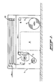
- the plant shown in Fig. 1 comprises a housing 1, in which is disposed rotatably a first roller 2 from which a web of material 3 runs to a device 5.
- a second roller 6 is also supported rotatably in the housing, and the web 7 of material runs from it via a guide roller 8 also to the device 5.
- From the device 5 the web of material runs via a guide roller 9 to a schematically shown accumulator 10, and from here to, for example, a printing machine.
- the device 5 serves to connect the web 7 of material coming from the (new) roll 6 to the web 3 of material, and when this splice has been made to cut through the old web 3 of material, so that after this only material from roll 6 is fed to the printing machine (not shown). While the webs of material are being interconnected the roll 2 is stopped, while the printing machine can continue to work with the material stored in the accumulator 10.
- the layout of the plant 1 shown in the drawing has the advantage that a fairly large free space A is present between the two rollers, and this space can be used for the operating personnel, who thus have easy access to the device 5 for carrying out operating activities.
- the invention in fact lies in the design of the device 5, part of which is shown schematically in Fig. 2.
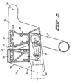
- This figure shows a frame 11, in which two pressure elements 12 and 13 are suspended opposite each other.
- Each pressure element in fact comprises two parallel side plates which are situated a distance away from each other, and which are each suspended movably in the frame, and between which a pressure bar 14, which will be described in greater detail later with reference to Figs. 3 and 4, is fitted.
- Fig. 2 shows only one of the side plates 15, 16 of each pressure element.
- the plate 15 is hingedly connected at 17 to an arm 18, which is in turn hingedly connected at 19 to the frame 11.
- the plate 16 is also hingedly connected at 20 to an arm 21, which is in turn hingedly connected at 22 to the frame 11.
- the arm 18 carries a roller 23, while the arm 21 carries a roller 24.
- the plate 15 has on the side facing away from the hinge point 17 a guide wheel 25 which is guided in a guide channel 26 which is disposed running virtually horizontally in the frame 11.
- the plate 16 is provided with a guide wheel 27, which is guided in a guide channel 28 of the frame 11.
- the two pressure elements 12 and 13 are disposed with their suspensions and guides symmetrical relative to an imaginary horizontal central plane between the two pressure elements.
- the suspension of the respective plates 15 and 16 provides the possibility for the plate 15 therefore to be moved to the right from the position shown by solid lines in the drawing, in which case the arm 18 pivots anticlockwise about the point 19, and the plate 15 turns through about 90 o until said plate and the arm 18 and the roller 23 take up the positions shown by dashed lines. It will be clear that the plate 16 and the arm 21 can be moved in a similar manner, in which case the arm 21 then rotates in a clockwise direction.
- the guides 26, 28 running essentially horizontally are provided at the lefthand end in the drawing with a vertical-running part 26a and 28a respectively. These parts make it possible for the pressure elements 12 and 13 to be moved towards and away from each other again into the folded state shown by solid lines, as will be explained below.
- a spring element 29 presses the top pressure element 12 against the force of gravity into its raised rest position.
- the other free end of the square lever 32 is connected to a piston/cylinder assembly 33, which is hingedly connected at the other side to the frame.
- the cutting element 30 lies in the central plane between the two pressure elements 12 and 13, in which the hinge point 31 of the lever 32 is also situated.
- the square lever 32 can rotate about the hinge point 31, and the wire cutting element 30 can then move upwards as desired into a slit 34 of the plate 15, or downwards into a slit 35 of the plate 16.
- the cutting element carries out a cutting action on the web of material lying above or below said cutting element.
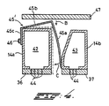
- Fig. 3 shows schematically a cross-section of the bottom pressure element 13, in which it must be imagined that the top pressure element 12 is designed identically, albeit symmetrically relative to the horizontal central plane between the two pressure elements.
- This figure shows the plate 16, with the pressure bar 14 in cross-section.
- the pressure bar 14 in fact comprises two parallel bars 14a and 14b which are situated a distance away from each other, and which are located on either side of the slit 35 and leave a slit between them.
- each bar 14a, 14b is provided with a pressure face 36, 37 which is made of a flexible rubber or plastic material.
- the rear face 36 viewed in the direction of movement of the web of material, serves as a pressure face for bringing about the join, while the face 37 serves to hold the web of material in the manner described below.
- the bars 14a and 14b in fact extend between two plates 16 lying a distance away from each other, and in the central area between these two plates 16 provision is made for a cover plate 38 on the two bars 14a and 14b, on which a connecting piece 39 is fastened.
- a piston/cylinder assembly 40 is connected at one side to said connecting piece and at the other side to the frame 11. This piston/cylinder assembly 40 serves to move the pressure element 13 to the right out of the position shown by solid lines in Fig. 2, during which movement the pressure element 13 carries out a rotary movement through approximately 90 o , so that the pressure faces 36 and 37 come to rest approximately vertically on the outside of the device (in other words, adjacent to space A in Fig. 1), and are accessible for the operating personnel.
- a vacuum line 41 is also connected to the connecting piece 39, a connection being made through the connecting piece 39 between an internal compartment of the respective bars 14a and 14b and this vacuum line.
- each bar 14a and 14b has an internal compartment 42, 43 which adjoins the relevant wall containing the pressure faces 36 and 37.
- a number of small apertures 44 which connect the relevant compartments 42 and 43 to the outside air are disposed in said walls.
- a cutting plate 45 is disposed between the two bars 14a and 14b against one of the bars. This cutting plate cooperates with the wire cutting element 30, for cutting through a web of material.
- this cutting plate 45 is designed as a flat plate fixed against the bar 14a, the cutting edge of which reaches virtually to the pressure face 36. This arrangement can lead to injury of the operating personnel during operation of the device, and for this reason it is preferable to design the cutting plate 45 in such a way that the cutting plate automatically retracts inside the slit between the bars 14a and 14b when the pressure element is not in operation. The principle of this automatic retraction is shown in Fig. 4.
- the cutting plate 45' is in the form of a U-shaped section, comprising a leg 45a which forms the actual cutting plate, a centre part 45b of the U, and a leg 45c which is considerably shorter than the opposite leg 45a.
- the cutting plate 45' is fastened by the leg 45c to the bar 14a by means of a bolt 46.
- the angle between the leg 45c and the centre part 45b is slightly greater than 90 o , so that the cutting plate 45' normally assumes the position shown by solid lines, in which the centre part 45b and the leg 45a are away from the bar 14, and the free end of the leg 45a is retracted inside the space between the two bars 14a and 14b.
- the web 7 is torn off in such a way that the free end of the web of material does not project beyond the pressure face 36.
- a vacuum in the internal compartments 42 and 43 of the bars 14a and 14b the web of material is sucked against the pressure face through the presence of the apertures 44.
- a double-sided adhesive strip is then applied by the operating personnel to the web of material lying against the pressure faces.
- the pressure element is then moved from the position shown by dotted lines again to the left, until said element is in the position shown by solid lines.
- the bar 49 here ensures that the length of the web of material remains the same in the two end positions of this element, and the web of material thus does not slip over the pressure face during this movement.
- the web 3 of material is stopped, and the pressure elements 12 and 13 are pressed with force against each other by suitable pressure elements, so that the two webs of material go against each other and adhere to each other by means of the adhesive strip. It will be clear that when they are pressed against each other the wire cutting element 30 is between the two webs of material.
- the old web of material is cut through by means of the cutting element 30, to which end said cutting element in the example described is moved downwards by means of the lever 32 and the cylinder 33.
- the pressure element 13 falls down again by the force of gravity, and the pressure element 12 is pressed upwards by the spring element 29.
- the cutting element 30 can now return to its neutral position and, by driving of the new roll 6, the web of material coming off this roll is guided via the device 5 to the accumulator 10 and the printing machine.
- the old roll 2 can be removed and is replaced by a new roll.
Landscapes
- Replacement Of Web Rolls (AREA)
Claims (8)
- Vorrichtung zum Verbinden des hinteren Endes einer ersten Materialbahn (3), die einer Behandlung oder Verfahrensoperation in Flußabwärtsrichtung der Vorrichtung (5) unterliegt, mit dem vorderen Ende einer zweiten Materialbahn (7), mit einem Gestell (1) mit Führungsrollen (9, 23, 24), die einen Laufweg für die erste Materialbahn (3) bilden, mit zwei Andruckelementen (12, 13), die an einer von beiden Seiten des Laufwegs aneinander angepaßt und im rechten Winkel zu dem Laufweg aufeinander zu und voneinander weg bewegbar sind, wobei jedes Druckelement (12, 13) einen Träger (14; 14a; 14b) enthält, der zwischen zwei Seitenplatten (15, 16) fixiert ist, die an dem Gestell bewegbar aufgehängt sind, wobei ferner jeder Träger mit einem Schlitz (34, 35) versehen ist, der sich in Längsrichtung des Trägers erstreckt und eine Druckfläche (36, 37) aufweist, die sich über ihre ganze Länge quer zu der Richtung des Laufweges erstreckt, sowie mit Schneidmitteln (30, 45, 45a) zum Schneiden durch das hintere Ende der ersten Materialbahn, dadurch gekennzeichnet, daß die Schlitze (34, 35) von den Druckflächen (36, 37) ausgehen und miteinander verbunden sind, wenn die Träger aneinander anliegen, und daß in der Höhe der Schlitze (34, 35) zwischen den zwei Trägern ein Draht-Schneidelement (30) gelagert ist, das zum Schneiden durch das hintere Ende der ersten Materialbahn (3) von einer zentralen Lage in den einen oder anderen Schlitz (34, 35) hinein verschiebbar ist.
- Vorrichtung nach Anspruch 1, dadurch gekennzeichnet, daß jede der beiden Seitenplatten (15, 16), durch die jeder Träger (14) bewegbar an dem Gestell (1) aufgehängt ist, mit einem Punkt (17, 20) eines Armes (18, 21) verbunden ist, der drehbar an dem Gestell befestigt ist, und an einem anderen Punkt (25, 27) bewegbar in einer an dem Gestell befestigten Führung (26, 28) in der Weise geführt ist, daß jeder Träger in Richtung des Stromaufwärtsendes des Laufweges bewegbar ist und dabei so rotiert, daß seine Druckfläche (36, 37) zur Präparation des hinteres Endes der zweiten Materialbahn (7) freigelegt wird.
- Vorrichtung nach Anspruch 2, dadurch gekennzeichnet, daß jeder Arm (18, 21), der drehbar an dem Gestell befestigt ist, eine Führungsrolle (23, 24) für die betreffende Materialbahn trägt.
- Vorrichtung nach einem oder mehreren der vorangehenden Ansprüche 1 - 3, dadurch gekennzeichnet, daß der Schlitz (34, 35) jedes Druckträgers (14) eine Schneidplatte (45, 45a) enthält, die mit dem Draht-Schneidelement (30) zusammenarbeitet.
- Vorrichtung nach Anspruch 4, dadurch gekennzeichnet, daß die Schneidplatte (45a) so angeordnet ist, daß sie in dem Schlitz (34, 35) kippbar ist und in der Arbeitsstellung des Druckelementes (12, 13) von einer zurückgezogenen Ruhestellung in ihre Arbeitsstellung bewegt wird.
- Vorrichtung nach einem oder mehreren der vorangehenden Ansprüche, dadurch gekennzeichnet, daß das Draht-Schneidelement (30) zwischen den Enden von zwei drehbar auf dem Gestell (1) angeordneten Hebeln (32) angeordnet ist, deren andere Enden mit einer Kolben/Zylinder-Anordnung (33) verbunden sind, und daß der Drehpunkt (31) der Hebel in der Mittelebene zwischen den beiden Druckelementen (12, 13) liegt.
- Vorrichtung nach einem oder mehreren der vorangehenden Ansprüche 1 - 6, dadurch gekennzeichnet, daß jeder Druckträger (14) aus zwei Trägern (14a, 14b) besteht, die parallel zueinander liegen und zwischen sich den Schlitz (34, 35) freilassen.
- Vorrichtung nach Anspruch 7, dadurch gekennzeichnet, daß jeder Träger (14a, 14b) des Druckträgers eine innere Kammer (42, 43) aufweist, die an die Wand des die Druckfläche bildenden Trägers anschließt, daß jede Kammer mit einer Vakuumleitung verbunden ist, und daß die die Druckfläche (36, 37) bildende Wand mit einer Vielzahl von Öffnungen (44) versehen ist, die die Kammer mit der Außenluft verbinden.
Applications Claiming Priority (2)
| Application Number | Priority Date | Filing Date | Title |
|---|---|---|---|
| NL8801829A NL8801829A (nl) | 1988-07-19 | 1988-07-19 | Inrichting voor het met elkaar verbinden van twee materiaalbanen. |
| NL8801829 | 1988-07-19 |
Publications (2)
| Publication Number | Publication Date |
|---|---|
| EP0427748A1 EP0427748A1 (de) | 1991-05-22 |
| EP0427748B1 true EP0427748B1 (de) | 1993-10-06 |
Family
ID=19852650
Family Applications (1)
| Application Number | Title | Priority Date | Filing Date |
|---|---|---|---|
| EP89908524A Expired - Lifetime EP0427748B1 (de) | 1988-07-19 | 1989-07-18 | Vorrichtung zum verbinden von zwei materialbahnen |
Country Status (6)
| Country | Link |
|---|---|
| US (1) | US5207859A (de) |
| EP (1) | EP0427748B1 (de) |
| JP (1) | JP2710848B2 (de) |
| DE (1) | DE68909791T2 (de) |
| NL (1) | NL8801829A (de) |
| WO (1) | WO1990001012A1 (de) |
Families Citing this family (3)
| Publication number | Priority date | Publication date | Assignee | Title |
|---|---|---|---|---|
| DE4021443A1 (de) * | 1990-07-05 | 1992-01-09 | Voith Gmbh J M | Einrichtung zur befestigung eines klebestreifens am bahnende und am tambour, den die warenbahn bildet |
| US5679207A (en) * | 1996-04-02 | 1997-10-21 | Eastman Kodak Company | Non-alternating lap splicing device |
| JP2004285528A (ja) | 2003-03-25 | 2004-10-14 | Showa Co | 作業用手袋 |
Family Cites Families (12)
| Publication number | Priority date | Publication date | Assignee | Title |
|---|---|---|---|---|
| SE306861B (de) * | 1963-10-04 | 1968-12-09 | Niepmann & Co Maschf Fr | |
| US3440126A (en) * | 1966-02-28 | 1969-04-22 | Eastman Kodak Co | Web splicer |
| DE2361300A1 (de) * | 1973-12-08 | 1975-06-12 | Agfa Gevaert Ag | Klebemaschine und schneidevorrichtung |
| US3886031A (en) * | 1974-06-10 | 1975-05-27 | Compensating Tension Controls | Web lap splicer |
| ES484893A0 (es) * | 1979-10-10 | 1980-11-01 | Torres Martinez M | Perfeccionamientos en sistemas de empalme automatico de bandas laminadas o bobinas de papel |
| US4374576A (en) * | 1981-02-02 | 1983-02-22 | Compensating Tension Controls, Inc. | Semi-automatic roll winding machine |
| US4455190A (en) * | 1983-04-20 | 1984-06-19 | Butler Automatic Inc. | Web splicer |
| GB2141108B (en) * | 1983-05-17 | 1985-10-30 | Koyo Jidoki | Continuous feeding tape |
| IT1180789B (it) * | 1984-07-10 | 1987-09-23 | Sasib Spa | Dispositivo per la giunzione di nastri in particolare di nastri di carta da sigarette |
| DE3439313C2 (de) * | 1984-10-26 | 1994-07-07 | Focke & Co | Vorrichtung zum Verbinden von Bahnen aus Verpackungsmaterial |
| GB2170177A (en) * | 1985-01-29 | 1986-07-30 | Harland Mach Syst | Joining webs |
| US4859270A (en) * | 1987-09-11 | 1989-08-22 | Martin Automatic, Inc. | In-register web splicer |
-
1988
- 1988-07-19 NL NL8801829A patent/NL8801829A/nl not_active Application Discontinuation
-
1989
- 1989-07-18 JP JP1506739A patent/JP2710848B2/ja not_active Expired - Lifetime
- 1989-07-18 EP EP89908524A patent/EP0427748B1/de not_active Expired - Lifetime
- 1989-07-18 WO PCT/NL1989/000058 patent/WO1990001012A1/en not_active Ceased
- 1989-07-18 US US07/613,677 patent/US5207859A/en not_active Expired - Fee Related
- 1989-07-18 DE DE89908524T patent/DE68909791T2/de not_active Expired - Fee Related
Also Published As
| Publication number | Publication date |
|---|---|
| DE68909791D1 (de) | 1993-11-11 |
| JPH03506021A (ja) | 1991-12-26 |
| NL8801829A (nl) | 1990-02-16 |
| EP0427748A1 (de) | 1991-05-22 |
| DE68909791T2 (de) | 1994-03-03 |
| JP2710848B2 (ja) | 1998-02-10 |
| WO1990001012A1 (en) | 1990-02-08 |
| US5207859A (en) | 1993-05-04 |
Similar Documents
| Publication | Publication Date | Title |
|---|---|---|
| CA1250559A (en) | Apparatus for joining sheets of packaging material | |
| US6314971B1 (en) | Dispenser for cleaning paper | |
| JPS6258313U (de) | ||
| NZ201962A (en) | Splicing webs | |
| JPH0261393B2 (de) | ||
| BR8905313A (pt) | Maquina bobinadora para material em forma de folha,especialmente papel ou cartao | |
| JPH0585466B2 (de) | ||
| EP0119255B1 (de) | Gewebebehandlungsvorrichtung | |
| EP0427748B1 (de) | Vorrichtung zum verbinden von zwei materialbahnen | |
| EP0394579A1 (de) | Doppelstationseinwickelmaschine | |
| ITMI20012454A1 (it) | Dispositivo per l'immagazzinamento e lo svolgimento di rulli di materiale in macchine per legatoria | |
| ITMI950833U1 (it) | Dispositivo di taglio per il rifilo di confezioni di carta stampata in una macchina confezionatrice | |
| JP4638573B2 (ja) | 輪転印刷機の折り装置用の胴部材 | |
| EP0095790B1 (de) | Gerät zum Sammeln und vorübergehender Lagerung von Blättern | |
| EP0322186A2 (de) | Apparat und Verfahren zum Falzen | |
| US3072051A (en) | Sheet feeder for printing machine | |
| JP2001220030A (ja) | シートを案内するためのガイド装置およびガイド装置を運転する方法 | |
| US4729812A (en) | Service apparatus for machines using continuous strips of paper forms or sheets | |
| DE2628536C3 (de) | Vorrichtung zum Durchtrennen eines Streifens | |
| EP0095314A2 (de) | Federverpackungsmaschinen | |
| CH644499A5 (it) | Dispositivo per l'applicazione di filtri a sigarette. | |
| NL192874C (nl) | Werkwijze en inrichting voor het in afzonderlijke stukken heropwikkelen van een materiaalbaan. | |
| KR102302570B1 (ko) | 약봉지 스트립 슬리터 | |
| SU1294896A1 (ru) | Устройство дл резани и съема картона с форматного вала картоноделательной машины | |
| US1652417A (en) | Paper-folding machine |
Legal Events
| Date | Code | Title | Description |
|---|---|---|---|
| PUAI | Public reference made under article 153(3) epc to a published international application that has entered the european phase |
Free format text: ORIGINAL CODE: 0009012 |
|
| 17P | Request for examination filed |
Effective date: 19901205 |
|
| AK | Designated contracting states |
Kind code of ref document: A1 Designated state(s): DE FR GB NL SE |
|
| 17Q | First examination report despatched |
Effective date: 19911219 |
|
| GRAA | (expected) grant |
Free format text: ORIGINAL CODE: 0009210 |
|
| AK | Designated contracting states |
Kind code of ref document: B1 Designated state(s): DE FR GB NL SE |
|
| REF | Corresponds to: |
Ref document number: 68909791 Country of ref document: DE Date of ref document: 19931111 |
|
| ET | Fr: translation filed | ||
| PLBE | No opposition filed within time limit |
Free format text: ORIGINAL CODE: 0009261 |
|
| STAA | Information on the status of an ep patent application or granted ep patent |
Free format text: STATUS: NO OPPOSITION FILED WITHIN TIME LIMIT |
|
| 26N | No opposition filed | ||
| EAL | Se: european patent in force in sweden |
Ref document number: 89908524.5 |
|
| PGFP | Annual fee paid to national office [announced via postgrant information from national office to epo] |
Ref country code: GB Payment date: 19970619 Year of fee payment: 9 |
|
| PGFP | Annual fee paid to national office [announced via postgrant information from national office to epo] |
Ref country code: SE Payment date: 19970723 Year of fee payment: 9 |
|
| PG25 | Lapsed in a contracting state [announced via postgrant information from national office to epo] |
Ref country code: GB Free format text: LAPSE BECAUSE OF NON-PAYMENT OF DUE FEES Effective date: 19980718 |
|
| PG25 | Lapsed in a contracting state [announced via postgrant information from national office to epo] |
Ref country code: SE Free format text: LAPSE BECAUSE OF NON-PAYMENT OF DUE FEES Effective date: 19980719 |
|
| GBPC | Gb: european patent ceased through non-payment of renewal fee |
Effective date: 19980718 |
|
| EUG | Se: european patent has lapsed |
Ref document number: 89908524.5 |
|
| PGFP | Annual fee paid to national office [announced via postgrant information from national office to epo] |
Ref country code: FR Payment date: 19990721 Year of fee payment: 11 |
|
| PGFP | Annual fee paid to national office [announced via postgrant information from national office to epo] |
Ref country code: DE Payment date: 19991230 Year of fee payment: 12 |
|
| PG25 | Lapsed in a contracting state [announced via postgrant information from national office to epo] |
Ref country code: FR Free format text: LAPSE BECAUSE OF NON-PAYMENT OF DUE FEES Effective date: 20010330 |
|
| REG | Reference to a national code |
Ref country code: FR Ref legal event code: ST |
|
| PGFP | Annual fee paid to national office [announced via postgrant information from national office to epo] |
Ref country code: NL Payment date: 20010726 Year of fee payment: 13 |
|
| PG25 | Lapsed in a contracting state [announced via postgrant information from national office to epo] |
Ref country code: DE Free format text: LAPSE BECAUSE OF NON-PAYMENT OF DUE FEES Effective date: 20020501 |
|
| PG25 | Lapsed in a contracting state [announced via postgrant information from national office to epo] |
Ref country code: NL Free format text: LAPSE BECAUSE OF NON-PAYMENT OF DUE FEES Effective date: 20030201 |
|
| NLV4 | Nl: lapsed or anulled due to non-payment of the annual fee |
Effective date: 20030201 |