EP0428027A2 - Dispositif optique de mesure de distance - Google Patents
Dispositif optique de mesure de distance Download PDFInfo
- Publication number
- EP0428027A2 EP0428027A2 EP90121050A EP90121050A EP0428027A2 EP 0428027 A2 EP0428027 A2 EP 0428027A2 EP 90121050 A EP90121050 A EP 90121050A EP 90121050 A EP90121050 A EP 90121050A EP 0428027 A2 EP0428027 A2 EP 0428027A2
- Authority
- EP
- European Patent Office
- Prior art keywords
- laser
- light
- frequency
- measuring device
- optical distance
- Prior art date
- Legal status (The legal status is an assumption and is not a legal conclusion. Google has not performed a legal analysis and makes no representation as to the accuracy of the status listed.)
- Granted
Links
Images


Classifications
-
- G—PHYSICS
- G01—MEASURING; TESTING
- G01S—RADIO DIRECTION-FINDING; RADIO NAVIGATION; DETERMINING DISTANCE OR VELOCITY BY USE OF RADIO WAVES; LOCATING OR PRESENCE-DETECTING BY USE OF THE REFLECTION OR RERADIATION OF RADIO WAVES; ANALOGOUS ARRANGEMENTS USING OTHER WAVES
- G01S17/00—Systems using the reflection or reradiation of electromagnetic waves other than radio waves, e.g. lidar systems
- G01S17/02—Systems using the reflection of electromagnetic waves other than radio waves
- G01S17/06—Systems determining position data of a target
- G01S17/08—Systems determining position data of a target for measuring distance only
- G01S17/32—Systems determining position data of a target for measuring distance only using transmission of continuous waves, whether amplitude-, frequency-, or phase-modulated, or unmodulated
- G01S17/36—Systems determining position data of a target for measuring distance only using transmission of continuous waves, whether amplitude-, frequency-, or phase-modulated, or unmodulated with phase comparison between the received signal and the contemporaneously transmitted signal
-
- G—PHYSICS
- G01—MEASURING; TESTING
- G01S—RADIO DIRECTION-FINDING; RADIO NAVIGATION; DETERMINING DISTANCE OR VELOCITY BY USE OF RADIO WAVES; LOCATING OR PRESENCE-DETECTING BY USE OF THE REFLECTION OR RERADIATION OF RADIO WAVES; ANALOGOUS ARRANGEMENTS USING OTHER WAVES
- G01S17/00—Systems using the reflection or reradiation of electromagnetic waves other than radio waves, e.g. lidar systems
- G01S17/87—Combinations of systems using electromagnetic waves other than radio waves
Definitions
- the invention relates to an optical distance measuring device with a light source for emitting a light beam to the measurement object and with a device for determining the phase shift between the light reflected or backscattered on the measurement object and the emitted light.
- Such devices are used today when distances of a few 100 m are to be measured accurately and quickly. Since there are no detectors with which the vibrations of the visible or infrared measuring light can be observed directly, these measuring devices work with amplitude-modulated light beams.
- the applicant's electronic tachymeter represented such measuring devices. They have a relatively simple optical structure.
- a luminescence diode operated via an oscillator and an amplifier generates an amplitude-modulated light beam. This is sent to the measurement object, reflected by it and received and detected again by the device.
- the detector signal and a reference signal from the amplifier are mixed electronically with the signal of a wide oscillator. The phase difference between the detector signal and the reference signal is then determined.
- the measuring accuracy of the tachymeter is approximately 1 mm with a measuring distance of several 100 m. This corresponds to a relative measuring accuracy of 5 x 10 ⁇ 6. Only reflecting objects are suitable as measuring objects.
- WO 88/08519 describes a measuring device with a heterodyne-interferometric structure, which has even greater measuring accuracy if the measuring distance is smaller.
- This device uses two frequency-stabilized laser beams with different frequencies. From these two laser beams, two acousto-optical modulators generate four laser beams, each with different frequencies, by forming the sum frequency. The modulation frequencies required for this are generated by two electronic oscillators and impressed on the acousto-optical modulators.
- the measuring accuracy of this device depends on the measuring object. It is lower for scattered objects than for reflecting objects. This is also described in the article by R. Dändliker et al., Optics Letters, Vol. 13, No. 5, 339 (1988).
- the relative accuracy of such measuring devices depends on how exactly the relative phase difference between two measuring signals can be determined and how stable the phase of the amplitude-modulated light is. If a distance s is to be determined with an accuracy ⁇ s, the spectral uncertainty ⁇ f / f of the modulation frequency f must not be greater than the desired lateral uncertainty ⁇ s / s: ⁇ f / f ⁇ ⁇ / s
- the object of the present invention to provide a measuring device of the type mentioned at the beginning, the measuring accuracy of which is identical for reflecting and for scattering measuring objects.
- the measuring device should enable measurements with a relative error, which is smaller than 10 bei, with measuring times of less than 100 ms.
- the light source consists of two frequency-stabilized, multi-mode lasers with frequency spacings ⁇ f1 and ⁇ f2 between the modes and that the frequencies are selected so that the ratio ⁇ f1 / ⁇ f2 of the two frequency spacings is one against the number 1 small amount differs from an integer.
- Each of the two frequency-stabilized lasers emits several modes with high spectral sharpness.
- the frequency spacing between the modes of a laser has the same spectral sharpness as each individual mode itself.
- the frequency spacing is approximately 100 MHz to 10 GHz depending on the resonator length.
- two adjacent longitudinal modes of a helium-neon laser with a resonator length of 25 cm have a frequency spacing of 600 MHz.
- An additional advantage of the device according to the invention is that by dispensing with the use of frequency-stabilized electronic oscillators, the effort required is low.
- a particularly simple stabilization process is proposed in DE-PS 20 43 734.
- the two modes of a two-mode gas laser are separated by polarization optics and their intensities are measured.
- a control loop controls the discharge current so that the intensity ratio of both modes is constant.
- the spectral sharpness of the individual modes is also transferred to the frequency spacing between the modes. It is well known to use the high spectral sharpness of this frequency spacing for interferometric length measurements. Such interferometric devices already allow measurements with a relative accuracy that is better than 10 ⁇ 6. However, they always require highly reflective objects, usually triple flectors. In contrast, when using scattering objects, the intensity of the backscattered light is too low. In addition, the scatter leads to a decorrelation of the phase relationship of the measuring light
- An advantageous embodiment of the invention provides that the two lasers are each two-mode. Then the very simple stabilization method according to DE-PS 20 43 734 can be used for the two lasers. In addition, the proportion of laser light used as measuring light is also greatest when the lasers are each two-mode.
- the ratio ⁇ f1 / ⁇ f2 of the two frequency spacings of the two lasers should differ from the number 1 by less than 1%.
- a distance measuring device with a particularly simple optical structure provides that the modes of each laser are capable of interference, so that two amplitude-modulated laser beams with the modulation frequencies ⁇ f1 and ⁇ f2 arise.
- the measuring device contains a total of three detectors, one detector each for the reception of a partial beam of the superimposed modes of each laser.
- the third detector receives the light emitted by a laser to the measurement object and scattered or reflected on it. Two measuring steps are required to measure distance. In each measuring step, the phase difference is determined between the third and that detector which receives light from the same laser and therefore with the same modulation frequency as the third detector.
- both detector signals are mixed in phase with the signal of the remaining detector, so that the phase measurement even at the difference frequency ⁇ f12 ⁇ f1 - ⁇ f2 takes place.
- the two measuring steps differ in that the light from different lasers and thus different modulation frequencies is emitted to the measurement object in different measurement steps.
- a device for interchanging both laser beams is provided for this.
- the distance can be clearly determined from the two measured phase differences.
- This simple measuring device has the advantage over interferometric measuring devices that it has a large uniqueness range L of the measurement results.
- An interferometric measuring device corresponding to WO 88/08519 only has a similarly large uniqueness range if at least one of the optical laser frequencies can be tuned.
- a simple device of this type of high stability provides a mechanical chopping device which can alternately transmit light at two different locations.
- phase drifts between the detectors can be compensated for.
- the cause of such phase drifts can e.g. Changes in the signal processing times of the detectors due to temperature changes.
- the third detector alternately receives the light scattered or reflected on the measurement object or a part of the light to be emitted.
- a mechanical chopping device can also be used here alternately interrupts one of two beam paths.
- the counting frequency of the digital phase meter is given by the frequency spacing of the two modes of one of the two lasers.
- the high count rate then leads to a high digital resolution.
- the count is made with the large spectral sharpness of the frequency spacing of the two modes of a laser.
- (1) and (2) denote two two-mode lasers, which are described in more detail below.
- the beam splitters (3, 4) direct a partial beam of each laser onto a Wollaston prism (5, 6).
- the Wollaston prisms separate them both modes of each laser beam according to their polarization.
- the split modes are detected separately by twin photodiodes (7, 8) and two controllers (9, 10) obtain two control signals from the detector signals.
- the regulators (9, 10) control the discharge current of the respective laser via the laser power supplies (11, 12) so that both modes of a laser have the same intensity.
- the result is an amplitude-modulated light wave (15) whose modulation frequency ⁇ f 1 is given by the frequency spacing of the two modes.
- the two modes of the second laser (2) are superimposed in the same way by the second polarizer (14).
- the result is a second amplitude-modulated light wave (16) whose modulation frequency is ⁇ f2.
- Two beam splitters (17, 22) split the first amplitude-modulated wave (15) into two partial beams (18, 19) of equal intensity and the second amplitude-modulated wave (16) into two partial beams (23, 24) of equal intensity.
- a partial beam (19) of the first laser and a partial beam (23) of the second laser intersect at a point P 1, the two remaining partial beams (18, 24) intersect at a second point P 2.
- a mechanical chopping device (25) can alternately transmit light either through the point P1 or through the point P2.
- the largest part of the light is formed by the measuring beam (30), which is then transmitted to the measuring object (33) via a beam splitter prism (31) and a telescope (32).
- the beam splitter prism (31) deflects the light scattered or reflected on the measurement object (33) to the third photodiode (34).
- the beam splitter prism is designed as a polarizing beam splitter so that no surface reflections from the telescope (32) reach the third photodiode (34).
- a ⁇ / 4 plate (35) is arranged behind the telescope (32). The light reflected or scattered on the measurement object (33) passes through the ⁇ 4 plate (35) twice and is therefore polarized perpendicular to the surface reflections of the telescope.
- the mechanical chopping device (25) can transmit light through the point P1.
- the second photodiode (28) receives light of the modulation frequency ⁇ f2, while the other two photodiodes (29, 34) receive light of the modulation frequency ⁇ f1.
- the signals of the latter photodiodes (29, 34) are shifted in phase by a value 0 ⁇ 1 against each other.
- Two electronic mixers (36, 37) generate from the signals of the three photodiodes (28, 29, 34) two in the phase shifted by the value 0 ⁇ 1 electronic vibrations Differential frequency ⁇ f12 ⁇ f1 - ⁇ f2.
- a digital phase meter (38) determines the value 0 ⁇ 1 of the phase shift.
- the signal from the second detector (28) is used to generate the counting pulses of the digital phase meter (38).
- a single phase measurement is then carried out with a digital accuracy of 2 ⁇ ⁇ f12 / ⁇ f2.
- the mechanical chopping device (25) transmits light through the point P2.
- the second photodiode (28) receives light of the modulation frequency ⁇ f1
- the other two photodiodes (29, 34) receive light of the modulation frequency ⁇ f2.
- the signals of these latter photodiodes (29, 34) are now shifted in phase by a value 0 ⁇ 2 against each other. The value 0 ⁇ 2 of this phase shift is determined as described above. So that the digital accuracy remains constant, the signal from the first detector (29) is now used to generate the counting pulses of the digital phase meter (38).
- a switch (39) switches the trigger input of the digital phase meter at the frequency of the mechanical chopper between the first detector (28) and the second detector (29).
- the distance value s between the measuring device and the measurement object (33) is calculated. This distance value is unambiguous as long as s ⁇ c / 2 ⁇ f12.
- the maximum achievable relative measurement accuracy ⁇ s / s depends on the spectral uncertainty ⁇ f / f of the modulation frequency.
- the digital measuring accuracy ⁇ s and the uniqueness range are determined by the numerical values ⁇ f1 and ⁇ f2 of the mode distances of the two lasers (1, 2).
- the spectral course of the amplification of the first helium-neon laser is identified by (ZQa).
- the two adjacent longitudinal modes n1 and n1 + 1 lie above the laser threshold (21a).
- the phase shifts can be measured over several periods of the difference frequency ⁇ f12.
- the digital Error only 2 ⁇ / 12.010.
- the digital phase meter (38) can be provided in FIG. 1 with a switchover, which interchanges the two measuring inputs (38a, 38b) after each measuring cycle. This suppresses the influence of systematic differences between the voltage comparators of the digital phase meter (38).
- a further beam splitter (40) is provided for correcting phase drifts between the second detector (28) and the third detector (34) in the beam path (30) of the measuring light in front of the beam splitter prism (31) Measuring light (30) deflects to the third detector (34).
- a second mechanical chopping device (41) alternately interrupts this partial beam (43) and the beam path (42) of the light scattered or reflected on the measurement object (33).
- a phase correction value 0 ⁇ k is measured between the signals of the second detector (28) and the third detector (34). This phase correction value 0 ⁇ k is subtracted from the phase values 0 ⁇ 1 or 0 ⁇ 2.
- the polarization-optical division of the measurement light (30) and the light (42) scattered or reflected on the measurement object (33) is not ideal, since scattering always has a depolarizing effect.
- a geometric beam splitting which can be done, for example, by separate transmitting and receiving telescopes, is possible.
- the mechanical chopping devices (25, 41) can be replaced by liquid crystal arrangements or also by electro- or meganeto-optical switching elements. These are particularly preferable when short measurement times and therefore high chopping frequencies are important.
- two different lasers are used.
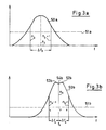
- the spectral course of the first laser is identified by (50a) in FIG. 3a.
- the maximum gain is at the frequency f3.
- the two modes n3 and n3 + 1 are above the laser threshold (51a). These two modes are linearly polarized perpendicular to each other.
- the frequency spacing between the modes is designated ⁇ f3.
- the frequency stabilization of this laser is carried out in accordance with the method described in FIG. 1.
- the second laser is three-mode.
- the three modes n4-1, n4 and n4 + 1 lie above the laser threshold (51b).
- the mode n4 is linearly polarized perpendicular to the other two modes.
- the frequency spacing of the modes ⁇ f4 is smaller than ⁇ f3 / 2.
- the spectral profile of the amplification (50b) has a minimum (54b) between the maxima (52b) and (53b), which is called the lamb dip.
- a polarization splitter splits the laser beam according to the polarization.
- the two modes n 4-1 and n 4 + 1 form the amplitude-modulated measuring beam with the modulation frequency 2 ⁇ f4.
- the intensity of the mode n4 is measured and used to stabilize the laser.
- a regulator adjusts the resonator length using piezo elements so that the frequency of mode n die coincides with the frequency of the lamb dip. The intensity of the mode n4 is then minimal.
Landscapes
- Physics & Mathematics (AREA)
- Electromagnetism (AREA)
- Engineering & Computer Science (AREA)
- Computer Networks & Wireless Communication (AREA)
- General Physics & Mathematics (AREA)
- Radar, Positioning & Navigation (AREA)
- Remote Sensing (AREA)
- Optical Radar Systems And Details Thereof (AREA)
- Instruments For Measurement Of Length By Optical Means (AREA)
- Measurement Of Optical Distance (AREA)
- Length Measuring Devices By Optical Means (AREA)
Applications Claiming Priority (2)
| Application Number | Priority Date | Filing Date | Title |
|---|---|---|---|
| DE3937268 | 1989-11-09 | ||
| DE3937268A DE3937268A1 (de) | 1989-11-09 | 1989-11-09 | Optische entfernungsmessvorrichtung |
Publications (3)
| Publication Number | Publication Date |
|---|---|
| EP0428027A2 true EP0428027A2 (fr) | 1991-05-22 |
| EP0428027A3 EP0428027A3 (en) | 1992-05-20 |
| EP0428027B1 EP0428027B1 (fr) | 1995-08-09 |
Family
ID=6393162
Family Applications (1)
| Application Number | Title | Priority Date | Filing Date |
|---|---|---|---|
| EP90121050A Expired - Lifetime EP0428027B1 (fr) | 1989-11-09 | 1990-11-02 | Dispositif optique de mesure de distance |
Country Status (4)
| Country | Link |
|---|---|
| US (1) | US5054912A (fr) |
| EP (1) | EP0428027B1 (fr) |
| JP (1) | JPH03170895A (fr) |
| DE (2) | DE3937268A1 (fr) |
Cited By (1)
| Publication number | Priority date | Publication date | Assignee | Title |
|---|---|---|---|---|
| EP0629880A1 (fr) * | 1993-06-10 | 1994-12-21 | Bertin & Cie | Télémètre |
Families Citing this family (23)
| Publication number | Priority date | Publication date | Assignee | Title |
|---|---|---|---|---|
| US5274361A (en) * | 1991-08-15 | 1993-12-28 | The United States Of America As Represented By The Secretary Of The Navy | Laser optical mouse |
| US5371587A (en) * | 1992-05-06 | 1994-12-06 | The Boeing Company | Chirped synthetic wavelength laser radar |
| GB2285550B (en) * | 1994-01-05 | 1997-09-17 | Creo Products Inc | Optical coordinate measuring system for large objects |
| US5793483A (en) * | 1996-02-07 | 1998-08-11 | Visidyne, Inc. | Optical measurement system |
| US5883706A (en) * | 1996-12-05 | 1999-03-16 | Northrop Grumman Corporation | Multiplexer for laser ranging devices and the like |
| DE19840049C5 (de) | 1998-09-02 | 2007-11-08 | Leica Geosystems Ag | Vorrichtung zur optischen Distanzmessung |
| US6483593B1 (en) | 1999-08-10 | 2002-11-19 | The Boeing Company | Hetrodyne interferometer and associated interferometric method |
| DE60102292T2 (de) | 2000-04-11 | 2005-02-17 | Oncology Automation, Inc. | Positionierungssysteme und zugehörige verfahren |
| US6646723B1 (en) * | 2002-05-07 | 2003-11-11 | The United States Of America As Represented By The Administrator Of The National Aeronautics And Space Administration | High precision laser range sensor |
| KR100468155B1 (ko) * | 2002-06-27 | 2005-01-26 | 한국과학기술원 | 이종모드 헬륨-네온 레이저와 슈퍼 헤테로다인위상측정법을 이용한 헤테로다인 레이저 간섭계 |
| WO2005047834A1 (fr) * | 2003-10-15 | 2005-05-26 | Polychromix Corporation | Processeur de lumiere assurant un controle de longueurs d'onde et procede associe |
| DE10352402B4 (de) * | 2003-11-10 | 2015-12-17 | Lasertec Gmbh | Laserbearbeitungsmaschine und Laserbearbeitungsverfahren |
| US7215413B2 (en) * | 2005-06-24 | 2007-05-08 | The Boeing Company | Chirped synthetic wave laser radar apparatus and methods |
| DE102009012646A1 (de) * | 2009-03-11 | 2010-09-23 | Amt Gmbh | Abstandsmessung |
| JP2014232005A (ja) * | 2013-05-28 | 2014-12-11 | 富士ゼロックス株式会社 | 計測装置 |
| US9488722B2 (en) * | 2013-06-05 | 2016-11-08 | Samsung Electronics Co., Ltd. | Time-of-flight ranging system and method with extended range |
| US10223793B1 (en) | 2015-08-05 | 2019-03-05 | Al Incorporated | Laser distance measuring method and system |
| US11935256B1 (en) | 2015-08-23 | 2024-03-19 | AI Incorporated | Remote distance estimation system and method |
| US9972098B1 (en) | 2015-08-23 | 2018-05-15 | AI Incorporated | Remote distance estimation system and method |
| US11069082B1 (en) | 2015-08-23 | 2021-07-20 | AI Incorporated | Remote distance estimation system and method |
| US10408604B1 (en) | 2015-09-07 | 2019-09-10 | AI Incorporated | Remote distance estimation system and method |
| US10346995B1 (en) | 2016-08-22 | 2019-07-09 | AI Incorporated | Remote distance estimation system and method |
| US12543966B2 (en) | 2023-03-10 | 2026-02-10 | Southern Methodist University | Tuned microwave resonant system for subcutaneous imaging |
Family Cites Families (6)
| Publication number | Priority date | Publication date | Assignee | Title |
|---|---|---|---|---|
| US3619057A (en) * | 1967-06-28 | 1971-11-09 | North American Aviation Inc | Geodetic laser survey system |
| GB1593733A (en) * | 1976-12-24 | 1981-07-22 | Marconi Co Ltd | Distance measuring instruments |
| US4163954A (en) * | 1977-03-11 | 1979-08-07 | Rockwell International Corporation | High energy coherent pulse source for laser system |
| US4666295A (en) * | 1983-03-17 | 1987-05-19 | Hughes Aircraft Company | Linear FM chirp laser |
| US4744653A (en) * | 1984-04-12 | 1988-05-17 | Matsushita Electric Industrial Co., Ltd. | Distance measurement by laser light |
| CH678108A5 (fr) * | 1987-04-28 | 1991-07-31 | Wild Leitz Ag |
-
1989
- 1989-11-09 DE DE3937268A patent/DE3937268A1/de not_active Withdrawn
-
1990
- 1990-11-02 DE DE59009499T patent/DE59009499D1/de not_active Expired - Fee Related
- 1990-11-02 EP EP90121050A patent/EP0428027B1/fr not_active Expired - Lifetime
- 1990-11-06 US US07/609,584 patent/US5054912A/en not_active Expired - Fee Related
- 1990-11-09 JP JP2302806A patent/JPH03170895A/ja active Pending
Cited By (2)
| Publication number | Priority date | Publication date | Assignee | Title |
|---|---|---|---|---|
| EP0629880A1 (fr) * | 1993-06-10 | 1994-12-21 | Bertin & Cie | Télémètre |
| FR2706602A1 (fr) * | 1993-06-10 | 1994-12-23 | Bertin & Cie | Télémètre. |
Also Published As
| Publication number | Publication date |
|---|---|
| JPH03170895A (ja) | 1991-07-24 |
| EP0428027B1 (fr) | 1995-08-09 |
| US5054912A (en) | 1991-10-08 |
| EP0428027A3 (en) | 1992-05-20 |
| DE3937268A1 (de) | 1991-05-16 |
| DE59009499D1 (de) | 1995-09-14 |
Similar Documents
| Publication | Publication Date | Title |
|---|---|---|
| EP0428027B1 (fr) | Dispositif optique de mesure de distance | |
| DE2235318C3 (de) | Verfahren zur opto-elektronischen Messung der Entfernung und der Höhendifferenz und Anordnung zur Durchführung des Verfahrens | |
| DE3608075C2 (fr) | ||
| DE19811550C2 (de) | Verfahren und Schaltungsanordnung zur Erzeugung von Frequenzsignalen | |
| DE602005001664T2 (de) | Optischer Entfernungsmesser | |
| DE3306709C2 (fr) | ||
| DE69127038T2 (de) | Entfernungsmessgerät | |
| DE69023279T2 (de) | Längenmessgerät. | |
| DE4314486C2 (de) | Absolutinterferometrisches Meßverfahren sowie dafür geeignete Laserinterferometeranordnung | |
| EP0826254B1 (fr) | Generateur de frequences optiques | |
| DE19743493C2 (de) | Verfahren und Vorrichtung zur Laserfrequenzmessung und -Stabilisierung | |
| DE102009024460B4 (de) | Auswerteeinrichtung, Messanordnung und Verfahren zur Weglängenmessung | |
| DE3650262T2 (de) | Differential-Interferometer mit flachem Spiegel. | |
| EP0074609B1 (fr) | Dispositif de mesure de vitesse de rotation | |
| DE69216464T2 (de) | Apparat zum Messen der Wellenlängenvariation | |
| EP0670469A1 (fr) | Gyroscope à laser en anneau du type brillouin | |
| AT399222B (de) | Interferometrische einrichtung zur messung der lage eines reflektierenden objektes | |
| EP0205406B1 (fr) | Télémètre électro-optique | |
| DE2229339B2 (de) | Zur Fein- und Grobmessung umschaltender elektrooptischer Entfernungsmesser | |
| WO1993005364A1 (fr) | Detecteur optique pour mouvements de rotation | |
| DE4035373C2 (de) | Faseroptischer Druck- oder Verschiebungsfühler | |
| DE69000564T2 (de) | Optisches system zum messen von linear- oder winkelaenderungen. | |
| EP0776536B1 (fr) | Source lumineuse multifrequence stabilisee et procede de production de longueur d'onde lumineuse synthetique | |
| DE60105791T2 (de) | Verfahren und vorrichtung zur messung der phasendifferenz zwischen intensitätsmodulierten optischen signalen | |
| EP1594020A1 (fr) | Procédé de génération d'un peigne de fréquences optique sans décalage et dispositif laser utilisant ce procédé |
Legal Events
| Date | Code | Title | Description |
|---|---|---|---|
| PUAI | Public reference made under article 153(3) epc to a published international application that has entered the european phase |
Free format text: ORIGINAL CODE: 0009012 |
|
| AK | Designated contracting states |
Kind code of ref document: A2 Designated state(s): CH DE FR GB LI NL SE |
|
| PUAL | Search report despatched |
Free format text: ORIGINAL CODE: 0009013 |
|
| AK | Designated contracting states |
Kind code of ref document: A3 Designated state(s): CH DE FR GB LI NL SE |
|
| 17P | Request for examination filed |
Effective date: 19921113 |
|
| 17Q | First examination report despatched |
Effective date: 19940216 |
|
| GRAA | (expected) grant |
Free format text: ORIGINAL CODE: 0009210 |
|
| AK | Designated contracting states |
Kind code of ref document: B1 Designated state(s): CH DE FR GB LI NL SE |
|
| PG25 | Lapsed in a contracting state [announced via postgrant information from national office to epo] |
Ref country code: NL Free format text: LAPSE BECAUSE OF NON-PAYMENT OF DUE FEES Effective date: 19950809 Ref country code: FR Free format text: THE PATENT HAS BEEN ANNULLED BY A DECISION OF A NATIONAL AUTHORITY Effective date: 19950809 |
|
| REF | Corresponds to: |
Ref document number: 59009499 Country of ref document: DE Date of ref document: 19950914 |
|
| PG25 | Lapsed in a contracting state [announced via postgrant information from national office to epo] |
Ref country code: SE Effective date: 19951109 |
|
| GBT | Gb: translation of ep patent filed (gb section 77(6)(a)/1977) |
Effective date: 19951102 |
|
| NLV1 | Nl: lapsed or annulled due to failure to fulfill the requirements of art. 29p and 29m of the patents act | ||
| EN | Fr: translation not filed | ||
| PLBE | No opposition filed within time limit |
Free format text: ORIGINAL CODE: 0009261 |
|
| STAA | Information on the status of an ep patent application or granted ep patent |
Free format text: STATUS: NO OPPOSITION FILED WITHIN TIME LIMIT |
|
| 26N | No opposition filed | ||
| PGFP | Annual fee paid to national office [announced via postgrant information from national office to epo] |
Ref country code: GB Payment date: 19981012 Year of fee payment: 9 |
|
| PGFP | Annual fee paid to national office [announced via postgrant information from national office to epo] |
Ref country code: DE Payment date: 19981022 Year of fee payment: 9 |
|
| PGFP | Annual fee paid to national office [announced via postgrant information from national office to epo] |
Ref country code: CH Payment date: 19981023 Year of fee payment: 9 |
|
| PG25 | Lapsed in a contracting state [announced via postgrant information from national office to epo] |
Ref country code: GB Free format text: LAPSE BECAUSE OF NON-PAYMENT OF DUE FEES Effective date: 19991102 |
|
| PG25 | Lapsed in a contracting state [announced via postgrant information from national office to epo] |
Ref country code: LI Free format text: LAPSE BECAUSE OF NON-PAYMENT OF DUE FEES Effective date: 19991130 Ref country code: CH Free format text: LAPSE BECAUSE OF NON-PAYMENT OF DUE FEES Effective date: 19991130 |
|
| GBPC | Gb: european patent ceased through non-payment of renewal fee |
Effective date: 19991102 |
|
| REG | Reference to a national code |
Ref country code: CH Ref legal event code: PL |
|
| PG25 | Lapsed in a contracting state [announced via postgrant information from national office to epo] |
Ref country code: DE Free format text: LAPSE BECAUSE OF NON-PAYMENT OF DUE FEES Effective date: 20000901 |