EP0428036A2 - Optisches Kabel - Google Patents
Optisches Kabel Download PDFInfo
- Publication number
- EP0428036A2 EP0428036A2 EP90121159A EP90121159A EP0428036A2 EP 0428036 A2 EP0428036 A2 EP 0428036A2 EP 90121159 A EP90121159 A EP 90121159A EP 90121159 A EP90121159 A EP 90121159A EP 0428036 A2 EP0428036 A2 EP 0428036A2
- Authority
- EP
- European Patent Office
- Prior art keywords
- optical
- cable
- optical cable
- flat
- cable according
- Prior art date
- Legal status (The legal status is an assumption and is not a legal conclusion. Google has not performed a legal analysis and makes no representation as to the accuracy of the status listed.)
- Granted
Links
Images
Classifications
-
- G—PHYSICS
- G02—OPTICS
- G02B—OPTICAL ELEMENTS, SYSTEMS OR APPARATUS
- G02B6/00—Light guides; Structural details of arrangements comprising light guides and other optical elements, e.g. couplings
- G02B6/44—Mechanical structures for providing tensile strength and external protection for fibres, e.g. optical transmission cables
- G02B6/4401—Optical cables
- G02B6/4403—Optical cables with ribbon structure
- G02B6/4404—Multi-podded
-
- G—PHYSICS
- G02—OPTICS
- G02B—OPTICAL ELEMENTS, SYSTEMS OR APPARATUS
- G02B6/00—Light guides; Structural details of arrangements comprising light guides and other optical elements, e.g. couplings
- G02B6/44—Mechanical structures for providing tensile strength and external protection for fibres, e.g. optical transmission cables
- G02B6/4401—Optical cables
- G02B6/4403—Optical cables with ribbon structure
-
- G—PHYSICS
- G02—OPTICS
- G02B—OPTICAL ELEMENTS, SYSTEMS OR APPARATUS
- G02B6/00—Light guides; Structural details of arrangements comprising light guides and other optical elements, e.g. couplings
- G02B6/44—Mechanical structures for providing tensile strength and external protection for fibres, e.g. optical transmission cables
- G02B6/4401—Optical cables
- G02B6/4429—Means specially adapted for strengthening or protecting the cables
- G02B6/443—Protective covering
- G02B6/4431—Protective covering with provision in the protective covering, e.g. weak line, for gaining access to one or more fibres, e.g. for branching or tapping
Definitions
- the invention relates to optical cables for laying in the subscriber access area according to the preamble of claim 1.
- a directional coupler had been provided for connecting subscribers to broadband communication networks.
- a not inconsiderable additional attenuation occurs in the optical transmission path at the splice point.
- a splice is not as mechanically reliable as the undamaged fiber.
- the invention has for its object to provide a splice-free connection from the main cable to the individual participants in the subscriber access area, which is particularly inexpensive and easy to manufacture.
- This object is achieved according to the invention by the features of claim 1 described in the characterizing part. Developments of the invention are described in the subclaims.
- the optical cable according to the invention is particularly suitable for the installation of wide-area communication services in residential areas.
- the advantages over the prior art can be seen in the fact that the connection method with the cable according to the invention can be carried out with less effort and the connections have a high degree of reliability.
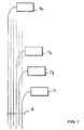
- FIG. 1 schematically shows an optical cable with subscriber connections
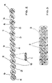
- FIG. 2 shows a flat cable in cross section
- FIG. 3 shows a cable made of several flat cables.
- the optical cable 2 generally runs in an installation channel past the subscribers T1, T2, T3, .. Tn (see FIG. 1).
- the sheath 7 of the cable is separated in the vicinity of a participant on the webs 6 and an optical element 3 is cut through above the connection point.
- the optical element 3 is severed so far above the connection point that the length up to the connection point is sufficient to have a sufficient connection length available after the optical element has been bent over to the subscriber Tk.
- the flat cable 2 can be easily separated into individual segments.
- the webs 6 in the jacket 7 of the flat cable 2 serve this purpose. After the two webs 6 have been separated on both sides, an optical element is still covered by parts of the jacket 7 and thus protected.
- the flat cable 2 contains tensile and compressive elements 4, which are also encased in the jacket 7.
- the optical element 3 preferably has a separate sheath 5. In this sheath is an optical ribbon cable 10 or a loose tube.
- the ribbon 10 has the advantage that it is easier to handle when installed in the subscriber area.
- flat cables 2 can also be put together to form a larger network.
- several flat cables 2 are stacked on top of one another and covered by a common sheath 9.
- the individual flat cables 2 can contain strain relief elements distributed in their sheath, but strain relief elements can also be contained in the sheath for the cable with the stacked flat cables.
Landscapes
- Physics & Mathematics (AREA)
- General Physics & Mathematics (AREA)
- Optics & Photonics (AREA)
- Light Guides In General And Applications Therefor (AREA)
- Glass Compositions (AREA)
- Optical Fibers, Optical Fiber Cores, And Optical Fiber Bundles (AREA)
- Photoreceptors In Electrophotography (AREA)
- Laser Surgery Devices (AREA)
Abstract
Description
- Die Erfindung betrifft optisches Kabel für die Verlegung im Teilnehmeranschlußbereich nach dem Oberbegriff des Anspruchs 1. Bisher hatte man zum Anschließen von Teilnehmern an Breitbandkommunikationsnetze beispielsweise für jeden Teilnehmer einen Richtkoppler vorgesehen. An der Spleißstelle tritt aber eine nicht unerhebliche Zusatzdämpfung im optischen übertragungsweg auf. Außerdem ist eine Spleißstelle mechanisch nicht so zuverlässig wie die unverletzte Glasfaser.
- Der Erfindung liegt die Aufgabe zugrunde, im Teilnehmeranschlußbereich eine spleißfreie Verbindung vom Hauptkabel zu den einzelnen Teilnehmern zu schaffen, welche besonders preisgünstig und leicht herstellbar ist. Diese Aufgabe wird nach der Erfindung durch die im Kennzeichen beschriebenen Merkmale des Anspruchs 1 gelöst. Weiterbildungen der Erfindung sind in den Unteransprüchen beschrieben.
- Das optische Kabel nach der Erfindung eignet sich besonders zur Installation von Breitkommunikationsdiensten in Wohngebieten. Die Vorteile gegenüber dem Stand der Technik sind darin zu sehen, daß das Anschlußverfahren mit dem erfindungsgemäßen Kabel mit weniger Aufwand durchgeführt werden kann und die Anschlüsse eine hohe Zuverlässigkeit aufweisen.
- Ein Ausführungsbeispiel der Erfindung wird nachstehend anhand der Zeichnung näher erläutert; dabei zeigt Fig. 1 schematisch ein optisches Kabel mit Teilnehmeranschlüssen, Fig. 2 ein Flachkabel im Querschnitt und Fig. 3 ein Kabel aus mehreren Flachkabeln.
- Das optische Kabel 2 verläuft im allgemeinen in einem Installationskanal an den Teilnehmern T1, T2, T3, .. Tn, vorbei (s. Fig. 1). Der Mantel 7 des Kabels wird in der Nähe eines Teilnehmers an den Stegen 6 aufgetrennt und ein optisches Element 3 oberhalb der Anschlußstelle durchgetrennt.
- Das optische Element 3 wird soweit oberhalb der Anschlußstelle durchgetrennt, daß die Länge bis zur Anschlußstelle ausreicht, um nach dem Umbiegen des optischen Elements zum Teilnehmer Tk eine ausreichende Anschlußlänge zur Verfügung zu haben.
- Das Flachkabel 2 ist in einzelne Segmente leicht auftrennbar. Dazu dienen die Stege 6 im Mantel 7 des Flachkabels 2. Nach dem beiderseitigen Auftrennen zweier Verbindungsstege 6 ist ein optisches Element noch von Teilen des Mantels 7 umhüllt und somit geschützt. Das Flachkabel 2 enhält zug- und stauchfeste Elemente 4, die ebenfalls von dem Mantel 7 umhüllt sind. Das optische Element 3 besitzt vorzugsweise eine separate Hülle 5. In dieser Hülle liegt ein optisches Bändchenkabel 10 oder eine Bündelader. Das Bändchen 10 hat den Vorteil, daß es bei der Installation im Teilnehmerbereich leichter zu handhaben ist.
- Mehrere Flachkabel 2 können auch zu einem größeren Verbund zusammengefügt werden. Dazu werden mehrere Flachkabel 2 übereinandergestapelt und von einem gemeinsamen Mantel 9 umhüllt. Die einzelnen Flachkabel 2 können in ihrem Mantel Zugentlastungselemente verteilt enthalten, es können aber auch im Mantel für das Kabel mit den gestapelten Flachkabeln Zugentlastungselemente enthalten sein.
Claims (6)
Applications Claiming Priority (2)
| Application Number | Priority Date | Filing Date | Title |
|---|---|---|---|
| DE3937804A DE3937804A1 (de) | 1989-11-14 | 1989-11-14 | Optisches kabel |
| DE3937804 | 1989-11-14 |
Publications (3)
| Publication Number | Publication Date |
|---|---|
| EP0428036A2 true EP0428036A2 (de) | 1991-05-22 |
| EP0428036A3 EP0428036A3 (en) | 1991-09-04 |
| EP0428036B1 EP0428036B1 (de) | 1994-10-05 |
Family
ID=6393476
Family Applications (1)
| Application Number | Title | Priority Date | Filing Date |
|---|---|---|---|
| EP90121159A Expired - Lifetime EP0428036B1 (de) | 1989-11-14 | 1990-11-06 | Optisches Kabel |
Country Status (4)
| Country | Link |
|---|---|
| EP (1) | EP0428036B1 (de) |
| AT (1) | ATE112637T1 (de) |
| DE (2) | DE3937804A1 (de) |
| FI (1) | FI98100C (de) |
Cited By (5)
| Publication number | Priority date | Publication date | Assignee | Title |
|---|---|---|---|---|
| EP0569679A1 (de) * | 1992-05-11 | 1993-11-18 | KABEL RHEYDT Aktiengesellschaft | Optisches Flachkabel |
| EP0629889A1 (de) * | 1993-06-17 | 1994-12-21 | Telia Ab | Optisches Kabel |
| FR2747201A1 (fr) * | 1996-04-03 | 1997-10-10 | Ruello Yves | Cable a fibres optiques et moyens pour la mise en oeuvre de celui-ci |
| FR2768234A1 (fr) * | 1997-09-11 | 1999-03-12 | France Telecom | Structure de cables a fibres optiques autoresistantes a la compression |
| US6295401B1 (en) | 1999-12-21 | 2001-09-25 | Siecor Operations, Llc | Optical fiber ribbon cables |
Families Citing this family (4)
| Publication number | Priority date | Publication date | Assignee | Title |
|---|---|---|---|---|
| DE4237676C1 (de) * | 1992-11-07 | 1994-02-10 | Ant Nachrichtentech | Lichtwellenleiterkabel |
| DE10035267B4 (de) * | 2000-07-20 | 2007-09-06 | CCS Technology, Inc., Wilmington | Optisches Kabel und Kanal- oder Rohrsystem mit einem installierten optischen Kabel |
| DE10140310A1 (de) * | 2001-08-16 | 2003-02-27 | Ccs Technology Inc | Laschband |
| GB2527580B (en) * | 2014-06-26 | 2021-07-21 | British Telecomm | Installation of cable connections |
Family Cites Families (7)
| Publication number | Priority date | Publication date | Assignee | Title |
|---|---|---|---|---|
| DK139490B (da) * | 1976-11-09 | 1979-02-26 | Nordiske Kabel Traad | Lysledende element til brug ved optisk transmission. |
| FR2428849A1 (fr) * | 1978-06-13 | 1980-01-11 | Fileca | Cable optique |
| DE3144205A1 (de) * | 1981-11-06 | 1983-05-19 | Siemens AG, 1000 Berlin und 8000 München | Lichtwellenleiterkabel fuer ein sternfoermig aufgebautes verzweigungsnetz |
| FR2543729B1 (fr) * | 1983-03-30 | 1985-12-27 | Cables De Lyon Geoffroy Delore | Cable composite pour la transmission de signaux de haute frequence et de signaux optiques |
| DE3526823A1 (de) * | 1985-07-26 | 1987-02-05 | Siemens Ag | Element mit mehreren lichtwellenleitern |
| GB8603706D0 (en) * | 1986-02-14 | 1986-03-19 | Bicc Plc | Multi-conductor ribbon structure |
| DE8906993U1 (de) * | 1989-06-07 | 1989-08-03 | Siemens AG, 1000 Berlin und 8000 München | Flachbandlichtleiter |
-
1989
- 1989-11-14 DE DE3937804A patent/DE3937804A1/de active Granted
-
1990
- 1990-11-06 EP EP90121159A patent/EP0428036B1/de not_active Expired - Lifetime
- 1990-11-06 AT AT90121159T patent/ATE112637T1/de not_active IP Right Cessation
- 1990-11-06 DE DE59007383T patent/DE59007383D1/de not_active Expired - Fee Related
- 1990-11-13 FI FI905610A patent/FI98100C/fi not_active IP Right Cessation
Cited By (7)
| Publication number | Priority date | Publication date | Assignee | Title |
|---|---|---|---|---|
| EP0569679A1 (de) * | 1992-05-11 | 1993-11-18 | KABEL RHEYDT Aktiengesellschaft | Optisches Flachkabel |
| EP0629889A1 (de) * | 1993-06-17 | 1994-12-21 | Telia Ab | Optisches Kabel |
| FR2747201A1 (fr) * | 1996-04-03 | 1997-10-10 | Ruello Yves | Cable a fibres optiques et moyens pour la mise en oeuvre de celui-ci |
| FR2768234A1 (fr) * | 1997-09-11 | 1999-03-12 | France Telecom | Structure de cables a fibres optiques autoresistantes a la compression |
| EP0902310A1 (de) * | 1997-09-11 | 1999-03-17 | France Telecom Sa | Strukturen bei Faseroptischen Kabeln mit automatischem Kompressionswiderstand |
| US6067394A (en) * | 1997-09-11 | 2000-05-23 | France Telecom, S.A. | Structures of optical fiber cables self-reinforced against compression |
| US6295401B1 (en) | 1999-12-21 | 2001-09-25 | Siecor Operations, Llc | Optical fiber ribbon cables |
Also Published As
| Publication number | Publication date |
|---|---|
| FI905610A0 (fi) | 1990-11-13 |
| EP0428036A3 (en) | 1991-09-04 |
| ATE112637T1 (de) | 1994-10-15 |
| FI98100B (fi) | 1996-12-31 |
| FI98100C (fi) | 1997-04-10 |
| EP0428036B1 (de) | 1994-10-05 |
| DE3937804A1 (de) | 1991-05-16 |
| DE59007383D1 (de) | 1994-11-10 |
| DE3937804C2 (de) | 1991-10-24 |
Similar Documents
| Publication | Publication Date | Title |
|---|---|---|
| EP0859257B1 (de) | Anordnung zur Abzweigung an einem mehrere Verseilelemente mit optischen Fasern enthaltenden Fernmeldekabel | |
| EP0149250B1 (de) | Verteilergestell für Glasfaser-Kabelenden | |
| DE69312106T2 (de) | Optisches Hilfsfaserkabel | |
| DE4305635A1 (de) | Nachrichtenkabel | |
| DE69527112T2 (de) | Wasserblockierendes ungefülltes Einzelrohrkabel | |
| DE2347408A1 (de) | Optischer faserstrang | |
| DE9206511U1 (de) | Verzweiger für Lichtleitfaser-Kabel | |
| DE3932251A1 (de) | Optisches kabel mit in kammern angeordneten bandleitungen | |
| EP0428036B1 (de) | Optisches Kabel | |
| DE3937693C2 (de) | ||
| DE69104558T2 (de) | Ungeschirmte Anschlussleitung für unterirdische Verlegung. | |
| DE4142729A1 (de) | Nachrichtenkabel | |
| DE3706677A1 (de) | Optisches nachrichtenkabel | |
| EP0072594A2 (de) | Optisches Nachrichtenkabel | |
| DE60124994T2 (de) | Glasfasertrennungs- und Zusammengruppierungsvorrichtung | |
| DE3937695C1 (en) | Optical cable for subscriber distribution in housing area - has markings on sheath surface giving unambiguous positions for fibres | |
| DE29518024U1 (de) | Nachrichtenkabel | |
| DE3144205A1 (de) | Lichtwellenleiterkabel fuer ein sternfoermig aufgebautes verzweigungsnetz | |
| DE19838351C2 (de) | Optisches Kabel und Kabelanordnung | |
| EP0569679A1 (de) | Optisches Flachkabel | |
| DE4306190B4 (de) | Lichtwellenleiter-Kabel | |
| EP0515827A2 (de) | Abzweigmuffe für ein optisches Kabel | |
| EP0477416B1 (de) | Optisches Kabel | |
| DE8901208U1 (de) | Bandleitung mit Lichtwellenleitern | |
| DE29513343U1 (de) | Lichtwellenleiter-Störlichtbogendetektor für Schaltanlagen zur Verteilung elektrischer Energie |
Legal Events
| Date | Code | Title | Description |
|---|---|---|---|
| PUAI | Public reference made under article 153(3) epc to a published international application that has entered the european phase |
Free format text: ORIGINAL CODE: 0009012 |
|
| AK | Designated contracting states |
Kind code of ref document: A2 Designated state(s): AT CH DE FR GB IT LI NL |
|
| PUAL | Search report despatched |
Free format text: ORIGINAL CODE: 0009013 |
|
| AK | Designated contracting states |
Kind code of ref document: A3 Designated state(s): AT CH DE FR GB IT LI NL |
|
| 17P | Request for examination filed |
Effective date: 19911115 |
|
| 17Q | First examination report despatched |
Effective date: 19930415 |
|
| RAP1 | Party data changed (applicant data changed or rights of an application transferred) |
Owner name: KABEL RHEYDT AKTIENGESELLSCHAFT |
|
| GRAA | (expected) grant |
Free format text: ORIGINAL CODE: 0009210 |
|
| AK | Designated contracting states |
Kind code of ref document: B1 Designated state(s): AT CH DE FR GB IT LI NL |
|
| REF | Corresponds to: |
Ref document number: 112637 Country of ref document: AT Date of ref document: 19941015 Kind code of ref document: T |
|
| ITF | It: translation for a ep patent filed | ||
| REF | Corresponds to: |
Ref document number: 59007383 Country of ref document: DE Date of ref document: 19941110 |
|
| GBT | Gb: translation of ep patent filed (gb section 77(6)(a)/1977) |
Effective date: 19941101 |
|
| ET | Fr: translation filed | ||
| PLBE | No opposition filed within time limit |
Free format text: ORIGINAL CODE: 0009261 |
|
| STAA | Information on the status of an ep patent application or granted ep patent |
Free format text: STATUS: NO OPPOSITION FILED WITHIN TIME LIMIT |
|
| 26N | No opposition filed | ||
| PGFP | Annual fee paid to national office [announced via postgrant information from national office to epo] |
Ref country code: GB Payment date: 19991012 Year of fee payment: 10 |
|
| PGFP | Annual fee paid to national office [announced via postgrant information from national office to epo] |
Ref country code: NL Payment date: 19991014 Year of fee payment: 10 Ref country code: CH Payment date: 19991014 Year of fee payment: 10 |
|
| PGFP | Annual fee paid to national office [announced via postgrant information from national office to epo] |
Ref country code: AT Payment date: 19991021 Year of fee payment: 10 |
|
| PGFP | Annual fee paid to national office [announced via postgrant information from national office to epo] |
Ref country code: DE Payment date: 19991025 Year of fee payment: 10 |
|
| PGFP | Annual fee paid to national office [announced via postgrant information from national office to epo] |
Ref country code: FR Payment date: 19991027 Year of fee payment: 10 |
|
| PG25 | Lapsed in a contracting state [announced via postgrant information from national office to epo] |
Ref country code: GB Free format text: LAPSE BECAUSE OF NON-PAYMENT OF DUE FEES Effective date: 20001106 Ref country code: AT Free format text: LAPSE BECAUSE OF NON-PAYMENT OF DUE FEES Effective date: 20001106 |
|
| PG25 | Lapsed in a contracting state [announced via postgrant information from national office to epo] |
Ref country code: LI Free format text: LAPSE BECAUSE OF NON-PAYMENT OF DUE FEES Effective date: 20001130 Ref country code: CH Free format text: LAPSE BECAUSE OF NON-PAYMENT OF DUE FEES Effective date: 20001130 |
|
| PG25 | Lapsed in a contracting state [announced via postgrant information from national office to epo] |
Ref country code: NL Free format text: LAPSE BECAUSE OF NON-PAYMENT OF DUE FEES Effective date: 20010601 |
|
| GBPC | Gb: european patent ceased through non-payment of renewal fee |
Effective date: 20001106 |
|
| REG | Reference to a national code |
Ref country code: CH Ref legal event code: PL |
|
| PG25 | Lapsed in a contracting state [announced via postgrant information from national office to epo] |
Ref country code: FR Free format text: LAPSE BECAUSE OF NON-PAYMENT OF DUE FEES Effective date: 20010731 |
|
| NLV4 | Nl: lapsed or anulled due to non-payment of the annual fee |
Effective date: 20010601 |
|
| PG25 | Lapsed in a contracting state [announced via postgrant information from national office to epo] |
Ref country code: DE Free format text: LAPSE BECAUSE OF NON-PAYMENT OF DUE FEES Effective date: 20010801 |
|
| REG | Reference to a national code |
Ref country code: FR Ref legal event code: ST |
|
| PG25 | Lapsed in a contracting state [announced via postgrant information from national office to epo] |
Ref country code: IT Free format text: LAPSE BECAUSE OF NON-PAYMENT OF DUE FEES;WARNING: LAPSES OF ITALIAN PATENTS WITH EFFECTIVE DATE BEFORE 2007 MAY HAVE OCCURRED AT ANY TIME BEFORE 2007. THE CORRECT EFFECTIVE DATE MAY BE DIFFERENT FROM THE ONE RECORDED. Effective date: 20051106 |