EP0428048A1 - Commande du moteur en fonction de l'embrayage d'un véhicule automobile - Google Patents
Commande du moteur en fonction de l'embrayage d'un véhicule automobile Download PDFInfo
- Publication number
- EP0428048A1 EP0428048A1 EP90121281A EP90121281A EP0428048A1 EP 0428048 A1 EP0428048 A1 EP 0428048A1 EP 90121281 A EP90121281 A EP 90121281A EP 90121281 A EP90121281 A EP 90121281A EP 0428048 A1 EP0428048 A1 EP 0428048A1
- Authority
- EP
- European Patent Office
- Prior art keywords
- injection pump
- clutch
- control unit
- vehicle
- electronic control
- Prior art date
- Legal status (The legal status is an assumption and is not a legal conclusion. Google has not performed a legal analysis and makes no representation as to the accuracy of the status listed.)
- Granted
Links
Images
Classifications
-
- B—PERFORMING OPERATIONS; TRANSPORTING
- B60—VEHICLES IN GENERAL
- B60K—ARRANGEMENT OR MOUNTING OF PROPULSION UNITS OR OF TRANSMISSIONS IN VEHICLES; ARRANGEMENT OR MOUNTING OF PLURAL DIVERSE PRIME-MOVERS IN VEHICLES; AUXILIARY DRIVES FOR VEHICLES; INSTRUMENTATION OR DASHBOARDS FOR VEHICLES; ARRANGEMENTS IN CONNECTION WITH COOLING, AIR INTAKE, GAS EXHAUST OR FUEL SUPPLY OF PROPULSION UNITS IN VEHICLES
- B60K26/00—Arrangement or mounting of propulsion-unit control devices in vehicles
- B60K26/04—Arrangement or mounting of propulsion-unit control devices in vehicles of means connecting initiating means or elements to propulsion unit
Definitions
- the invention relates to a device for controlling the engine in connection with the clutch of a motor vehicle, with an electronic control unit which controls the injection pump of the engine, which in turn is controlled via a charge control.
- a device for controlling an engine and a clutch of a motor vehicle which uses a clutch control device, which causes an exact control of the engine speed in the sense that a finely metered under the various conditions Starting and switching of the vehicle is made possible.
- the known device is comparatively complex in terms of the electronic and pneumatic means used.
- the object of the invention is to provide a control device of the type mentioned at the outset, which is of particularly simple construction and nevertheless effectively eliminates the start-up clutch jerk.
- the essence of the invention is to provide the electronic control unit, which is present on the vehicle anyway for various functions (for example speed limitation, anti-slip control and engine speed reduction during engine brake actuation, TS transmission), with an additional AND gate which gives the electronic control unit a vehicle standstill signal and inputs a clutch actuation signal of a person-operated, in particular foot-actuated clutch for the purpose of reducing or limiting the fuel fill quantity of the injection pump.
- a reset device provided in the charge control of the engine, preferably a pneumatic piston-cylinder arrangement, is used in a particularly simple manner for the adjustment or reset of the charge control lever of the injection pump during start-up.
- the invention therefore does not have a clutch engagement control device that is complicated in comparison to the aforementioned prior art, but instead only when starting (i.e. accelerating to start when the vehicle is stationary) the engine speed is limited in order to protect the drive train components from overload. Because of the simple construction, the invention is particularly suitable for control devices in series vehicles and in particular for retrofitting.
- the invention enables standardization with known solutions (speed limitation, ASR, engine braking system) ("modular system").
- ASR engine braking system
- module module
- trucks which are equipped with increasingly powerful engines and larger gears (12 to 16 gears)
- the driver often tends to get the highest possible Drive into gear.
- the engine swing moment is inevitably reduced by the invention, and a driver is forced to make optimum use of the transmission gears.
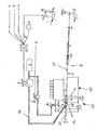
- the drawing shows a schematic representation of a device (20) for controlling the engine in connection with the foot-operated clutch (11) of a motor vehicle, which has an injection engine with an injection pump (10) which is controlled by the accelerator pedal (13) via a charge control (8). is controlled.
- the engine speed can be regulated between a minimum and a maximum speed using the accelerator pedal.
- the maximum speed is achieved by operating the accelerator pedal in the counterclockwise direction, as a result of which the charge control lever (12) of the injection pump (10) is pivoted clockwise.
- the force of the spring (22) takes effect, which returns the lever (12) to its original position.
- the filling control (8) described above also contains a resetting device (4) in the form of a pneumatically actuable piston-cylinder arrangement which is firmly integrated in the filling control system (8), in particular the free end of the piston rod (16) on the right as shown in the drawing. is connected to the Bowden cable (15) of the filling control (8).
- the latter piston rod end is also articulated to the free end of a support lever (14).
- the overall arrangement is such that the resetting device (4) or the piston-cylinder arrangement is located between the levers (12, 14).
- the pneumatic working chamber (19) of the piston-cylinder arrangement is connected via a pneumatic connection to a pneumatic proportionality valve (2), which is connected to the inlet side Compressed air tank (3) is connected.
- the proportionality valve (2) is controlled by an electronic control unit (1), which receives control signals from functional systems (A, B, C and D).
- the functional system (A) relates to a speed limitation, the functional system (B) an anti-slip control and the functional system (C) an engine brake (injection pump in minimum position).
- the aforementioned systems can be present in whole or in part in a vehicle.
- the electronic control unit (1) already present in the vehicle is now further expanded by the functional system (D), which in particular contains an AND gate on the input side of the electronic control unit, which has a vehicle standstill signal (s1) and a clutch actuation signal (s2) in the unit feeds.
- the vehicle stop signal (s1) is assigned to a speedometer (9) and is caused when a speed range of 0 to about 3 km / h is given in the vehicle.
- the clutch actuation signal (s2) is obtained when a foot-actuated clutch (11) is actuated in that an electric switch (7) is closed when the clutch pedal (11) is actuated.
- the electrical signal (s2) from the switch (7) is transmitted to the electronic control unit (1).
- the control unit (1) takes effect when the vehicle is at the same time, ie at the same time the electrical signal (s1) is present. Under the aforementioned two conditions, the electronic control unit (1) controls the proportionality valve (2), and it actuates the compressed air of the container (3), the reset device (4) by acting on the pneumatic working space (19) of the cylinder: the return The adjusting device (4) or piston-cylinder arrangement expands, the inner return spring (16) being compressed in the cylinder. Due to the expansion movement of the return device (4), which practically represents an "extension" of the Bowden cable (15), the filling control lever (12) of the injection pump (10) is reset in the counterclockwise direction due to the force of the spring (22); the engine speed is reduced accordingly.
- a reduction in the drive torque increase when starting is thus achieved.
- the engine speed cannot be increased beyond a preselected limit and the engine swing torque does not overload the drivetrain components.
- the illustrated system further comprises a further functional area (E), namely the function of the engine shutdown by an engine shutoff valve (5) and an engine shutoff cylinder (6) and the function of an engine brake (injection pump in the 0 position).
- E a further functional area
Landscapes
- Engineering & Computer Science (AREA)
- Chemical & Material Sciences (AREA)
- Combustion & Propulsion (AREA)
- Transportation (AREA)
- Mechanical Engineering (AREA)
- Control Of Vehicle Engines Or Engines For Specific Uses (AREA)
- Hydraulic Clutches, Magnetic Clutches, Fluid Clutches, And Fluid Joints (AREA)
Applications Claiming Priority (2)
| Application Number | Priority Date | Filing Date | Title |
|---|---|---|---|
| DE3937692A DE3937692A1 (de) | 1989-11-13 | 1989-11-13 | Einrichtung zur steuerung des motors in verbindung mit der kupplung eines kraftfahrzeugs |
| DE3937692 | 1989-11-13 |
Publications (2)
| Publication Number | Publication Date |
|---|---|
| EP0428048A1 true EP0428048A1 (fr) | 1991-05-22 |
| EP0428048B1 EP0428048B1 (fr) | 1992-10-28 |
Family
ID=6393411
Family Applications (1)
| Application Number | Title | Priority Date | Filing Date |
|---|---|---|---|
| EP90121281A Expired - Lifetime EP0428048B1 (fr) | 1989-11-13 | 1990-11-07 | Commande du moteur en fonction de l'embrayage d'un véhicule automobile |
Country Status (2)
| Country | Link |
|---|---|
| EP (1) | EP0428048B1 (fr) |
| DE (2) | DE3937692A1 (fr) |
Cited By (1)
| Publication number | Priority date | Publication date | Assignee | Title |
|---|---|---|---|---|
| EP0930424A3 (fr) * | 1998-01-15 | 2000-09-20 | Volkswagen Aktiengesellschaft | Méthode et dispositif pour améliorer le démarrage d'un véhicule à boíte de vitesse manuelle |
Families Citing this family (3)
| Publication number | Priority date | Publication date | Assignee | Title |
|---|---|---|---|---|
| DE19752276B4 (de) * | 1997-11-26 | 2005-11-24 | Zf Sachs Ag | Vorrichtung zur Steuerung eines Anfahrvorganges |
| DE10105322C1 (de) * | 2001-02-02 | 2002-08-14 | Daimler Chrysler Ag | Verfahren zum Betrieb eines Antriebsstrangs eines Kraftfahrzeugs |
| DE102004057511A1 (de) * | 2004-11-29 | 2006-06-08 | Volkswagen Ag | Motorsteuerung und Motorsteuerverfahren |
Citations (3)
| Publication number | Priority date | Publication date | Assignee | Title |
|---|---|---|---|---|
| FR2194233A6 (fr) * | 1968-07-03 | 1974-02-22 | Berliet Automobiles | |
| DE3334717A1 (de) * | 1983-09-26 | 1985-04-04 | Wabco Westinghouse Fahrzeugbremsen GmbH, 3000 Hannover | Einrichtung zur steuerung eines motors und einer kupplung eines kraftfahrzeugs |
| EP0130794B1 (fr) * | 1983-06-29 | 1988-03-09 | Isuzu Motors Limited | Méthode électronique pour le contrôle de véhicules |
-
1989
- 1989-11-13 DE DE3937692A patent/DE3937692A1/de not_active Withdrawn
-
1990
- 1990-11-07 EP EP90121281A patent/EP0428048B1/fr not_active Expired - Lifetime
- 1990-11-07 DE DE9090121281T patent/DE59000409D1/de not_active Expired - Lifetime
Patent Citations (3)
| Publication number | Priority date | Publication date | Assignee | Title |
|---|---|---|---|---|
| FR2194233A6 (fr) * | 1968-07-03 | 1974-02-22 | Berliet Automobiles | |
| EP0130794B1 (fr) * | 1983-06-29 | 1988-03-09 | Isuzu Motors Limited | Méthode électronique pour le contrôle de véhicules |
| DE3334717A1 (de) * | 1983-09-26 | 1985-04-04 | Wabco Westinghouse Fahrzeugbremsen GmbH, 3000 Hannover | Einrichtung zur steuerung eines motors und einer kupplung eines kraftfahrzeugs |
Non-Patent Citations (2)
| Title |
|---|
| PATENT ABSTRACTS OF JAPAN vol. 8, no. 164 (M-313)(1601) 28 Juli 84, & JP-A-59 58131 (TOYO KOGYO) 03 April 84, * |
| PATENT ABSTRACTS OF JAPAN vol. 8, no. 244 (M-337)(1681) 09 November 84, & JP-A-59 122744 (NISSAN JIDOSHA) 16 Juli 84, * |
Cited By (1)
| Publication number | Priority date | Publication date | Assignee | Title |
|---|---|---|---|---|
| EP0930424A3 (fr) * | 1998-01-15 | 2000-09-20 | Volkswagen Aktiengesellschaft | Méthode et dispositif pour améliorer le démarrage d'un véhicule à boíte de vitesse manuelle |
Also Published As
| Publication number | Publication date |
|---|---|
| DE3937692A1 (de) | 1991-05-16 |
| DE59000409D1 (de) | 1992-12-03 |
| EP0428048B1 (fr) | 1992-10-28 |
Similar Documents
| Publication | Publication Date | Title |
|---|---|---|
| DE2933075C2 (de) | Antriebs- und Bremsanlage von Kraftfahrzeugen | |
| DE3641244C2 (fr) | ||
| DE3728572A1 (de) | Einrichtung zur vortriebsregelung an kraftfahrzeugen | |
| DE3119153A1 (de) | Anordnung zum ermitteln des haftbeiwertes einer fahrbahn | |
| DE2732905A1 (de) | Einrichtung zum regeln der fahrgeschwindigkeit eines kraftfahrzeugs | |
| DE3143666C2 (fr) | ||
| DE102013213471A1 (de) | Kraftfahrzeug | |
| EP0900155A1 (fr) | Systeme pour produire un signal de freinage dans un vehicule a moteur | |
| DE4341213C2 (de) | Steuerung zur Geschwindigkeitsbeeinflussung eines Fahrzeuges | |
| DE3608751A1 (de) | Vorrichtung fuer kraftfahrzeuge mit vortriebsregelung | |
| DE3743308A1 (de) | Verfahren und vorrichtung zur ueberwachung eines antriebsmotorsollwertgeber | |
| EP0428048B1 (fr) | Commande du moteur en fonction de l'embrayage d'un véhicule automobile | |
| DE3608790A1 (de) | Vorrichtung fuer kraftfahrzeuge mit vortriebs- und geschwindigkeitskonstantregelung | |
| DE1755454A1 (de) | Einrichtung zum Ausgleich uebermaessiger Beschleunigungen bei Kraftfahrzeugen | |
| EP0962637B1 (fr) | Commande de puissance de moteur à combustion pour véhicule avec organe de réglage de puissance | |
| EP0306641A1 (fr) | Commande électrique de papillon pour moteur à combustion interne | |
| DE2856294A1 (de) | Einrichtung zum regeln der fahrgeschwindigkeit eines kraftfahrzeuges | |
| DE8602379U1 (de) | Vorrichtung zur Vortriebsregelung für Kraftfahrzeuge | |
| DE3112777A1 (de) | Kupplung fuer kraftfahrzeuge mit momentabhaengiger auskuppelvorrichtung | |
| DE102023203704A1 (de) | Fahrzeugbedienvorrichtung | |
| EP1258386B1 (fr) | Procédé de commande du mise en marche pour un train de propulsion | |
| DE3542058C1 (en) | Device for increasing the idling speed of an internal combustion engine | |
| DE69303693T2 (de) | Gerät zur Steuerung des Stillstands-Auskuppelns eines automatischen Getriebes | |
| DE3331597A1 (de) | Vorrichtung zum reduzieren des bremsmomentes von brennkraftmaschinen in kraftfahrzeugen | |
| EP0279057B1 (fr) | Dispositif de limitation du régime d'un moteur automobile |
Legal Events
| Date | Code | Title | Description |
|---|---|---|---|
| PUAI | Public reference made under article 153(3) epc to a published international application that has entered the european phase |
Free format text: ORIGINAL CODE: 0009012 |
|
| AK | Designated contracting states |
Kind code of ref document: A1 Designated state(s): DE FR GB IT NL SE |
|
| 17P | Request for examination filed |
Effective date: 19910605 |
|
| 17Q | First examination report despatched |
Effective date: 19920410 |
|
| GRAA | (expected) grant |
Free format text: ORIGINAL CODE: 0009210 |
|
| AK | Designated contracting states |
Kind code of ref document: B1 Designated state(s): DE FR GB IT NL SE |
|
| ITF | It: translation for a ep patent filed | ||
| ET | Fr: translation filed | ||
| REF | Corresponds to: |
Ref document number: 59000409 Country of ref document: DE Date of ref document: 19921203 |
|
| GBT | Gb: translation of ep patent filed (gb section 77(6)(a)/1977) |
Effective date: 19930202 |
|
| PLBE | No opposition filed within time limit |
Free format text: ORIGINAL CODE: 0009261 |
|
| STAA | Information on the status of an ep patent application or granted ep patent |
Free format text: STATUS: NO OPPOSITION FILED WITHIN TIME LIMIT |
|
| 26N | No opposition filed | ||
| EAL | Se: european patent in force in sweden |
Ref document number: 90121281.1 |
|
| PGFP | Annual fee paid to national office [announced via postgrant information from national office to epo] |
Ref country code: SE Payment date: 19991014 Year of fee payment: 10 |
|
| PGFP | Annual fee paid to national office [announced via postgrant information from national office to epo] |
Ref country code: GB Payment date: 19991129 Year of fee payment: 10 Ref country code: FR Payment date: 19991129 Year of fee payment: 10 |
|
| PGFP | Annual fee paid to national office [announced via postgrant information from national office to epo] |
Ref country code: NL Payment date: 19991130 Year of fee payment: 10 Ref country code: DE Payment date: 19991130 Year of fee payment: 10 |
|
| PG25 | Lapsed in a contracting state [announced via postgrant information from national office to epo] |
Ref country code: GB Free format text: LAPSE BECAUSE OF NON-PAYMENT OF DUE FEES Effective date: 20001107 |
|
| PG25 | Lapsed in a contracting state [announced via postgrant information from national office to epo] |
Ref country code: SE Free format text: THE PATENT HAS BEEN ANNULLED BY A DECISION OF A NATIONAL AUTHORITY Effective date: 20001129 |
|
| PG25 | Lapsed in a contracting state [announced via postgrant information from national office to epo] |
Ref country code: NL Free format text: LAPSE BECAUSE OF NON-PAYMENT OF DUE FEES Effective date: 20010601 |
|
| GBPC | Gb: european patent ceased through non-payment of renewal fee |
Effective date: 20001107 |
|
| EUG | Se: european patent has lapsed |
Ref document number: 90121281.1 |
|
| PG25 | Lapsed in a contracting state [announced via postgrant information from national office to epo] |
Ref country code: FR Free format text: LAPSE BECAUSE OF NON-PAYMENT OF DUE FEES Effective date: 20010731 |
|
| NLV4 | Nl: lapsed or anulled due to non-payment of the annual fee |
Effective date: 20010601 |
|
| PG25 | Lapsed in a contracting state [announced via postgrant information from national office to epo] |
Ref country code: DE Free format text: LAPSE BECAUSE OF NON-PAYMENT OF DUE FEES Effective date: 20010801 |
|
| REG | Reference to a national code |
Ref country code: FR Ref legal event code: ST |
|
| PG25 | Lapsed in a contracting state [announced via postgrant information from national office to epo] |
Ref country code: IT Free format text: LAPSE BECAUSE OF NON-PAYMENT OF DUE FEES;WARNING: LAPSES OF ITALIAN PATENTS WITH EFFECTIVE DATE BEFORE 2007 MAY HAVE OCCURRED AT ANY TIME BEFORE 2007. THE CORRECT EFFECTIVE DATE MAY BE DIFFERENT FROM THE ONE RECORDED. Effective date: 20051107 |