EP0428202A2 - Schiebezylinderschloss - Google Patents
Schiebezylinderschloss Download PDFInfo
- Publication number
- EP0428202A2 EP0428202A2 EP90202912A EP90202912A EP0428202A2 EP 0428202 A2 EP0428202 A2 EP 0428202A2 EP 90202912 A EP90202912 A EP 90202912A EP 90202912 A EP90202912 A EP 90202912A EP 0428202 A2 EP0428202 A2 EP 0428202A2
- Authority
- EP
- European Patent Office
- Prior art keywords
- cylinder assembly
- bolt
- plug
- detention
- cylinder
- Prior art date
- Legal status (The legal status is an assumption and is not a legal conclusion. Google has not performed a legal analysis and makes no representation as to the accuracy of the status listed.)
- Ceased
Links
Images

Classifications
-
- E—FIXED CONSTRUCTIONS
- E05—LOCKS; KEYS; WINDOW OR DOOR FITTINGS; SAFES
- E05B—LOCKS; ACCESSORIES THEREFOR; HANDCUFFS
- E05B17/00—Accessories in connection with locks
- E05B17/20—Means independent of the locking mechanism for preventing unauthorised opening, e.g. for securing the bolt in the fastening position
- E05B17/2084—Means to prevent forced opening by attack, tampering or jimmying
-
- E—FIXED CONSTRUCTIONS
- E05—LOCKS; KEYS; WINDOW OR DOOR FITTINGS; SAFES
- E05B—LOCKS; ACCESSORIES THEREFOR; HANDCUFFS
- E05B13/00—Devices preventing the key or the handle or both from being used
- E05B13/10—Devices preventing the key or the handle or both from being used formed by a lock arranged in the handle
- E05B13/105—Devices preventing the key or the handle or both from being used formed by a lock arranged in the handle the handle being a pushbutton
-
- E—FIXED CONSTRUCTIONS
- E05—LOCKS; KEYS; WINDOW OR DOOR FITTINGS; SAFES
- E05B—LOCKS; ACCESSORIES THEREFOR; HANDCUFFS
- E05B17/00—Accessories in connection with locks
- E05B17/0054—Fraction or shear lines; Slip-clutches, resilient parts or the like for preventing damage when forced or slammed
Definitions
- the present invention relates to locks and more particularly is concerned with cylinder locks of the kind where the cylinder assembly is borne in a casing for axial movement as a whole, whereby to shift a plunger or other locking member into its locking position.
- Such locks are used e.g. in various furniture and automotive applications.
- a retainer bolt In the locking (inner) condition of the assembly, a retainer bolt extends laterally from the cylinder into a detention in the casing, this bolt being withdrawn when the proper key is turned within the cylinder to permit the assembly to move backward, normally under spring bias, to its unlocking (outer) condition.
- the present invention is concerned to improve the security of such cylinder locks against attacks aimed at forcibly withdrawing the cylinder assembly from its locking condition.
- tools are available, as described e.g. in European patent application no 0297172, which comprise a hardened screw held in a frame which can be screwed into the keyway of a cylinder lock, two other clamping screws threaded through the frame then being turned against the lock casing to force the frame away from the lock.
- the invention proposes a cylinder lock of the kind stated above where the cylinder barrel and plug are formed separately from a member which bears the retainer bolt and through which the locking member is shifted, said member being connected to the barrel by fastening means adapted to fail when subject to a predetermined load in the unlocking axial direction of the cylinder assembly which is less than that which will cause failure of the retainer bolt or its detention when in the locking condition.
- the illustrated lock has a casing composed of parts 1, 2 and 3, parts 1 and 2 being screwed and pinned together to define a chamber wherein a cylinder assembly 4 is borne for limited sliding movement as a whole.
- the cylinder assembly comprises a two-part barrel (or stator) 5 and a plug (or rotor) 6 and its operation can be based upon any conventional arrangement of pin or disc tumblers (not shown), it being understood that the plug 6 will normally be blocked by the tumblers against rotary movement relative to the barrel 5 but can be released for turning relative to the barrel by the insertion of a proper key into the keyway 7 to set the tumblers into their releasing positions.
- the cylinder assembly will comprise three rows of pin tumblers, adapted to engage in dimples formed in the two sides and one edge of a flat key bit of complementary section to the keyway 7.
- the cylinder assembly is keyed against rotation relative to the lock casing by means of a pin 8 ( Figure 3) held in a recess in the periphery of the barrel 5 and engaging in a longitudinal groove 9 in the casing part 1, and the limits of its sliding movement in the casing are set by abutment of an external annular flange 10 on the barrel against faces 11 and 12 of the casing.
- a sliding member 13 formed at one end as a locking plunger 14.
- the plunger 14 protrudes from the rear end of casing part 1 to accomplish the locking or control function for which the lock is intended.
- the member 13 is formed with a transverse groove 15 in which it carries a lateral retainer bolt 16, of the configuration more fully shown in Figures 3 and 4.
- the tip of this bolt extends into a detention 17 in the casing part 1 to retain the member 13 and cylinder assembly 4 in the inner position, against the bias of a spring 18.
- the bolt 16 has a central profiled aperture 19 of the configuration shown in Figures 3 and 4, by which the bolt can be driven to extend and retract through the turning of a coupling element 20 associated with the cylinder plug 6.
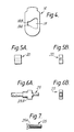
- the coupling element 20 is in the form of a rectangular-sectioned block as shown in Figure 5 which is normally held completely within the confines of a complementarily-sectioned recess 21 in the rear end of the plug 6.
- the coupling element is biased to that position by means of a spring 22 acting through the retainer 23 shown in Figures 1 and 6.
- the cylinder assembly 4 and member 13 are freed to slide under the bias of the spring 18 to their outer axial position, in which the locking plunger 14 is withdrawn to its unlocking condition, whereupon return rotation of the key throws out the bolt once more to engage in a second detention 24 in the casing part 1, by engagement of the coupling element 20 with the drive face 19B of the bolt.
- the mechanism can be returned to the locking condition by repeat use of the key to withdraw the bolt 16, pressing the cylinder assembly in to extend the locking plunger 14, and throwing out the bolt 16 into the detention 17 once more.
- the means whereby the member 13 is attached to the cylinder assembly 4 comprise two screws 25 ( Figures 3 and 7) which extend through bores in the member 13 parallel to but offset from the central axis of the lock, and which are threaded into complementary tapped holes in the rear of the barrel 5.
- These screws have reduced-section necks 25A or are otherwise so formed as to fail under a predetermined axial tensile stress, which is so chosen as to ensure that in the event of an attack aimed at forcibly withdrawing the cylinder assembly 4 in the locking condition of the lock, it is the screws 25 which will fail in preference to any other part of the structure, and in particular before there is a risk of failure of the bolt 16 or its detention 17.
- the cylinder assembly 4 can be withdrawn to what is normally its unlocking condition, as limited by the abutment of flange 10 against face 12, but the member 13 with its locking plunger 14 will be retained in the locking condition by the bolt 16. This method of attack will therefore not succeed in withdrawing the plunger 14. Furthermore, as the cylinder assembly is drawn forwardly away from member 13 the coupling element 20 will tend to disengage from its retainer 23 while the latter will be ejected a short distance by the spring 22 and will then drop down with its shoulder 23A in front of the bolt 16.
- the invention is equally applicable to sliding cylinder locks of the kind where locking is achieved by a simple push-button action on the cylinder assembly, the retainer bolt being spring-biased to engage in a detention in the inner axial condition and use of the key being necessary only for unlocking.
Landscapes
- Lock And Its Accessories (AREA)
Applications Claiming Priority (2)
| Application Number | Priority Date | Filing Date | Title |
|---|---|---|---|
| GB8925546 | 1989-11-11 | ||
| GB898925546A GB8925546D0 (en) | 1989-11-11 | 1989-11-11 | Locks |
Publications (2)
| Publication Number | Publication Date |
|---|---|
| EP0428202A2 true EP0428202A2 (de) | 1991-05-22 |
| EP0428202A3 EP0428202A3 (en) | 1991-11-13 |
Family
ID=10666166
Family Applications (1)
| Application Number | Title | Priority Date | Filing Date |
|---|---|---|---|
| EP19900202912 Ceased EP0428202A3 (en) | 1989-11-11 | 1990-11-05 | Sliding cylinder locks |
Country Status (2)
| Country | Link |
|---|---|
| EP (1) | EP0428202A3 (de) |
| GB (2) | GB8925546D0 (de) |
Cited By (1)
| Publication number | Priority date | Publication date | Assignee | Title |
|---|---|---|---|---|
| EP0645509A1 (de) * | 1993-09-29 | 1995-03-29 | Indespension Limited | Ein Schloss |
Families Citing this family (2)
| Publication number | Priority date | Publication date | Assignee | Title |
|---|---|---|---|---|
| GB0120104D0 (en) * | 2001-08-17 | 2001-10-10 | Guardian Security Group Ltd | An anti-theft locking device |
| GB2435669A (en) * | 2006-03-02 | 2007-09-05 | Martin Charles Wright | Lock device for retractable security post |
Family Cites Families (2)
| Publication number | Priority date | Publication date | Assignee | Title |
|---|---|---|---|---|
| US4074548A (en) * | 1976-12-08 | 1978-02-21 | General Motors Corporation | Lock cylinder assembly |
| GB2120311B (en) * | 1982-05-18 | 1985-12-04 | Chubb & Sons Lock & Safe Co | Locks |
-
1989
- 1989-11-11 GB GB898925546A patent/GB8925546D0/en active Pending
-
1990
- 1990-11-05 EP EP19900202912 patent/EP0428202A3/en not_active Ceased
- 1990-11-07 GB GB9024242A patent/GB2237841B/en not_active Expired - Fee Related
Cited By (1)
| Publication number | Priority date | Publication date | Assignee | Title |
|---|---|---|---|---|
| EP0645509A1 (de) * | 1993-09-29 | 1995-03-29 | Indespension Limited | Ein Schloss |
Also Published As
| Publication number | Publication date |
|---|---|
| GB9024242D0 (en) | 1990-12-19 |
| GB2237841A (en) | 1991-05-15 |
| GB2237841B (en) | 1993-08-25 |
| GB8925546D0 (en) | 1990-01-04 |
| EP0428202A3 (en) | 1991-11-13 |
Similar Documents
| Publication | Publication Date | Title |
|---|---|---|
| US4630457A (en) | Lock with removable plug | |
| US4823575A (en) | Cylinder lock and key | |
| EP1019601B1 (de) | Zylinderschloss | |
| DE69417530T2 (de) | Gegen Einbruch widerstandsfähiges Zylinderschloss | |
| US5076081A (en) | Key for interchangable core lock | |
| US4222253A (en) | Steering lock for motor vehicles | |
| US3418833A (en) | Tamperproof cylinder lock | |
| US5010753A (en) | Interchangeable core lock | |
| US6910356B2 (en) | Anti-pick mogul cylinder | |
| US5437176A (en) | Key and rotary lock cylinder for safety lock | |
| US5964110A (en) | Key lock with removable plug | |
| CN1075588C (zh) | 一种带闭锁圆柱的锁定装置 | |
| US4624119A (en) | Tumbler lock | |
| US6058751A (en) | Free-wheeling lock | |
| US7003994B2 (en) | Lock enhancing device | |
| US4416129A (en) | Cylinder lock with key removable plug | |
| EP0677632A2 (de) | Zylinderschloss mit austauschbarem Kern, wobei der Riegel ausrichtbar und begränzt drehbar ist | |
| SE465473B (sv) | Uppbrytningssaekra laas, speciellt foer bilar | |
| US5617750A (en) | Pin tumbler locks and keys therefor | |
| EP1451516A1 (de) | Vorrichtung und verfahren zum sperren einer feuerwaffe gegen unberechtigte verwendung | |
| EP0428202A2 (de) | Schiebezylinderschloss | |
| EP0978608A1 (de) | Zylinderschlossmechanismus | |
| US6948345B1 (en) | Lock enhancement arrangement | |
| US4724690A (en) | Security bolt | |
| DE1428528B2 (de) | Zylinderschloßbefestigung in einem Aufnahmegehäuse |
Legal Events
| Date | Code | Title | Description |
|---|---|---|---|
| PUAI | Public reference made under article 153(3) epc to a published international application that has entered the european phase |
Free format text: ORIGINAL CODE: 0009012 |
|
| AK | Designated contracting states |
Kind code of ref document: A2 Designated state(s): BE DE NL |
|
| PUAL | Search report despatched |
Free format text: ORIGINAL CODE: 0009013 |
|
| AK | Designated contracting states |
Kind code of ref document: A3 Designated state(s): BE DE NL |
|
| 17P | Request for examination filed |
Effective date: 19920502 |
|
| 17Q | First examination report despatched |
Effective date: 19921020 |
|
| STAA | Information on the status of an ep patent application or granted ep patent |
Free format text: STATUS: THE APPLICATION HAS BEEN REFUSED |
|
| 18R | Application refused |
Effective date: 19940210 |