EP0428210A1 - Circulation pump for circulating the cooling liquid for internal combustion engines - Google Patents
Circulation pump for circulating the cooling liquid for internal combustion engines Download PDFInfo
- Publication number
- EP0428210A1 EP0428210A1 EP90202949A EP90202949A EP0428210A1 EP 0428210 A1 EP0428210 A1 EP 0428210A1 EP 90202949 A EP90202949 A EP 90202949A EP 90202949 A EP90202949 A EP 90202949A EP 0428210 A1 EP0428210 A1 EP 0428210A1
- Authority
- EP
- European Patent Office
- Prior art keywords
- pump
- pump body
- circulation pump
- tank
- hollow
- Prior art date
- Legal status (The legal status is an assumption and is not a legal conclusion. Google has not performed a legal analysis and makes no representation as to the accuracy of the status listed.)
- Withdrawn
Links
Images



Classifications
-
- F—MECHANICAL ENGINEERING; LIGHTING; HEATING; WEAPONS; BLASTING
- F04—POSITIVE - DISPLACEMENT MACHINES FOR LIQUIDS; PUMPS FOR LIQUIDS OR ELASTIC FLUIDS
- F04D—NON-POSITIVE-DISPLACEMENT PUMPS
- F04D29/00—Details, component parts, or accessories
- F04D29/40—Casings; Connections of working fluid
- F04D29/42—Casings; Connections of working fluid for radial or helico-centrifugal pumps
- F04D29/426—Casings; Connections of working fluid for radial or helico-centrifugal pumps especially adapted for liquid pumps
-
- F—MECHANICAL ENGINEERING; LIGHTING; HEATING; WEAPONS; BLASTING
- F05—INDEXING SCHEMES RELATING TO ENGINES OR PUMPS IN VARIOUS SUBCLASSES OF CLASSES F01-F04
- F05D—INDEXING SCHEME FOR ASPECTS RELATING TO NON-POSITIVE-DISPLACEMENT MACHINES OR ENGINES, GAS-TURBINES OR JET-PROPULSION PLANTS
- F05D2260/00—Function
- F05D2260/60—Fluid transfer
- F05D2260/602—Drainage
- F05D2260/6022—Drainage of leakage having past a seal
Definitions
- the present invention is concerned with a circulation pump for circulating the cooling liquid for internal combustion engines.
- the circulation pumps which cause the internal combustion engines cooling liquid to circulate are schematically constituted by a fixed structural portion, generally denominated "pump body", inside whose interior a rotary shaft is housed, which transmits the revolutionary motion to an impeller of the type with centrifugal blades installed externally relatively to the pump body, inside the circulation loop of the cooling liquid; between the fixed portion of the pump (i.e., the pump body) and the impeller a sealing gasket is interposed.
- Said sealing gasket is constituted by two portions, the one of which, constrained to the pump body, is generally made from a ceramic material and the other of which is made from a much softer material, capable of fitting the contact surface of the first gasket portion.
- drain channel is provided in the pump body, which drain channel puts the chamber inside which said sealing gasket is housed into communication with the external environment, being thus useful in order to cause the liquid which may be produced inside said chamber, to drain.
- the causes for such production of liquid matter are various. Said production can occur owing to the continuous evaporation of the liquid film formed between the mutual contact surfaces of the two portions of the sealing gasket -- which evaporation is caused by the overheating generated by the friction between said contact surfaces -- and due to the unavoidable leakages of liquid which take place along the perimeter of the gasket and are caused, e.g., by a not perfect fitting up of the gasket; and finally, owing to the not complete effectiveness of the gasket during the first operating hours, when the contact surface of that portion of the gasket which is integral with the pump body, must still perfectly fit the contact surface of that portion of the gasket, which is integral with the impeller.
- the above said drain channel provided through the pump body also allows the cooling liquid possibly leaked -- in much larger amounts -- into the interior of the pump when the sealing gasket is not perfectly operating, to escape to the outside; therefore, in such event, the above said drain channel also constitutes an useful means in order to detect the malfunctioning of the sealing gasket and hence, summing-up, the malfunctioning of the circulation pump.
- the purpose of the instant invention is of proposing a circulation pump for circulating the cooling liquid for internal combustion engines in which the discharge of the liquid matter which is formed in the nearby of the sealing gasket takes place in a reliable and industrially cheap way.
- a circulation pump for circulating the cooling liquid for internal combustion engines comprising a pump body inside whose interior a revolutionary shaft is installed, which transmits the revolutionary motion to an impeller installed outside the body pump and installed inside the circulation loop of the cooling liquid, with a sealing gasket being interposed between said pump body and said impeller, characterized in that said circulation pump comprised, provided inside the pump body, a tank suitable for collecting the liquid which is formed inside the interior of the pumo in the nearby of the sealing gasket, which tank is in communication with a channel leading to the outside of said pump body.
- a pump according to the present invention is generally indicated.
- the pump body 11 is provided with a hollow 12 obtained, in the specific case herein shown, as an enbloc piece with the pump body, by means of machining operations with tool machines.
- the hollow 12 has a cylindrical shape and is radiused to a coaxial duct 13 which connects the interior of said hollow with the chamber 14 inside which the sealing gasket -- generally indicated with the reference numeral 15 -- is housed.
- Said gasket 15 is subdivided, as shown in figure, into two portions 16 and 17, the one of which is integral with the impeller 18 through a support ring 19 constrained to the shaft 20; the other sealing gasket portion, 17, is urged against the first portion 16, by means of an elastic element 21 which reacts against the shell 22 constrained to the pump body 11.
- the two portions 16 and 17 of the gasket 15 are respectively made from a ceramic material and carbon, such as to achieve the best results in terms of tightness against the dispersions or the leakages of the liquid contained inside the region 32.
- the hollow 12 becomes capable of constituting a collecting tank inside which the liquid coming from the chamber 14 is collected, when said hollow 12 is frontally stopped by means of a cap 23, which is installed in its end position by means of a forcing operation.
- a cap 23 which is installed in its end position by means of a forcing operation.
- the two positions can be observed in detail, and on an enlarged scale, which the cap 23 takes relatively to the pump body 11, before and after the above said forcing operation; the end position is taken, as one can see from Figure 4, at the cost of a deformation of the wall 24 of the seat, which is made from a softer and lower-tenacity material, e.g., cast iron, caused by the same cap, made from a harder and higher-tenacity material, such as, e.g., steel.
- Said operation of forcing and deformation secures the perfect tightness of the stopping of the tank, with a very low industrial manufacturing cost.
- the tank 12 is connected with the outside of the pump body by means of the channel 25; this connection performs the task of keeping low the pressure value inside the tank, such as to enable the liquid coming from the chamber 14 to easily drain through the duct 13; the diameter of this latter can also reach relatively small values by virtue of the presence of the channel 25 and, what's more important in this respect, the drain of the liquid through the duct 13 can continue to take place also when, as time goes on, the free cross section of the same duct gets narrower owing to the continuous sedimentation of the substances contained in the cooling liquid used for the cooling of the internal combustion engines.
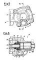
- the feature consisting of placing the collecting tank 12 into communication with the outside is also displayed by the different form of practical embodiment illustrated in Figures 5, 6, 7 and 8. Also in this case, the same structural elements as of the preceding form of practical embodiment are present and are indicated with the same reference numerals, with an apex added; what is different in the two solutions, is the arrangement of the tank 12′, which in this second case is vertical and not oblique, as well as the different construction technology used, in that the second pump body 11′ is manufactured by means of an aluminum casting operation, differently from the preceding pump body 11, which is made from cast iron by machining with tool machines.
- the collecting tank 12′ is put into communication with the outside through the ring chamber 14′ and a drain channel 26 provided parallel to the axis of the pump by means of a simple groove provided at the bearing housing surface (the bearing is not shown in the figures), which bearing is interposed between the pump body and the shaft integral with the impeller.
- the drain of the liquid along the duct 13′ is favoured in this case not so much in that an increase in the internal pressure inside the tank 12′ is prevented, but rather because the occurrence of a depressure inside the chamber 14′ is prevented; both of these circumstances would in fact hinder the liquid from freely draining from the chamber 14′ to the tank 12′.
- the volume of the collecting tank is, in any case, large enough to prevent the liquid -- i.e., the liquid which, as said, is formed in very small amounts inside the chamber 14 or 14′ owing to the above specified causes -- from escaping from the pump body to the outside.
Landscapes
- Engineering & Computer Science (AREA)
- Mechanical Engineering (AREA)
- General Engineering & Computer Science (AREA)
- Structures Of Non-Positive Displacement Pumps (AREA)
Applications Claiming Priority (2)
| Application Number | Priority Date | Filing Date | Title |
|---|---|---|---|
| IT22389A IT1237768B (it) | 1989-11-15 | 1989-11-15 | Pompa di circolazione del liquido di raffreddamento per motori a combustione interna. |
| IT2238989 | 1989-11-15 |
Publications (1)
| Publication Number | Publication Date |
|---|---|
| EP0428210A1 true EP0428210A1 (en) | 1991-05-22 |
Family
ID=11195628
Family Applications (1)
| Application Number | Title | Priority Date | Filing Date |
|---|---|---|---|
| EP90202949A Withdrawn EP0428210A1 (en) | 1989-11-15 | 1990-11-07 | Circulation pump for circulating the cooling liquid for internal combustion engines |
Country Status (2)
| Country | Link |
|---|---|
| EP (1) | EP0428210A1 (it) |
| IT (1) | IT1237768B (it) |
Cited By (8)
| Publication number | Priority date | Publication date | Assignee | Title |
|---|---|---|---|---|
| EP1048851A2 (de) | 1999-04-29 | 2000-11-02 | TCG UNITECH Aktiengesellschaft | Kühlwasserpumpe für eine Brennkraftmaschine |
| EP1319843A3 (de) * | 2001-12-12 | 2004-01-28 | Bayerische Motoren Werke Aktiengesellschaft | Kühlmittelpumpe |
| FR2845729A1 (fr) * | 2002-10-14 | 2004-04-16 | Renault Sa | Agencement de pompe hydraulique dans un moteur, et pompe pour un tel agencement |
| EP1748193A2 (en) | 2005-07-26 | 2007-01-31 | Aisin Seiki Kabushiki Kaisha | Water pump |
| EP1921323A3 (en) * | 2006-11-10 | 2010-09-15 | Aisin Seiki Kabushiki Kaisha | Water pump |
| ITTV20100155A1 (it) * | 2010-12-03 | 2012-06-04 | Jacuzzi Europ | Pompa comprendente un dispositivo per l'individuazione e il controllo di un trafilamento di liquido |
| CN102996218A (zh) * | 2011-09-12 | 2013-03-27 | 株式会社久保田 | 水冷发动机 |
| GB2533907A (en) * | 2014-10-10 | 2016-07-13 | Ford Global Tech Llc | A detachable water pump reservoir |
Citations (3)
| Publication number | Priority date | Publication date | Assignee | Title |
|---|---|---|---|---|
| US2375085A (en) * | 1943-01-30 | 1945-05-01 | Curtis Pump Co | Booster pump seal construction |
| GB2033979A (en) * | 1978-10-27 | 1980-05-29 | Bayerische Motoren Werke Ag | Coolant Pump for Liquid-cooled Internal Combustion Engines |
| DE3931938A1 (de) * | 1988-09-27 | 1990-04-05 | Aisin Seiki | Wasserpumpe |
-
1989
- 1989-11-15 IT IT22389A patent/IT1237768B/it active IP Right Grant
-
1990
- 1990-11-07 EP EP90202949A patent/EP0428210A1/en not_active Withdrawn
Patent Citations (3)
| Publication number | Priority date | Publication date | Assignee | Title |
|---|---|---|---|---|
| US2375085A (en) * | 1943-01-30 | 1945-05-01 | Curtis Pump Co | Booster pump seal construction |
| GB2033979A (en) * | 1978-10-27 | 1980-05-29 | Bayerische Motoren Werke Ag | Coolant Pump for Liquid-cooled Internal Combustion Engines |
| DE3931938A1 (de) * | 1988-09-27 | 1990-04-05 | Aisin Seiki | Wasserpumpe |
Cited By (16)
| Publication number | Priority date | Publication date | Assignee | Title |
|---|---|---|---|---|
| EP1048851A2 (de) | 1999-04-29 | 2000-11-02 | TCG UNITECH Aktiengesellschaft | Kühlwasserpumpe für eine Brennkraftmaschine |
| US6270312B1 (en) | 1999-04-29 | 2001-08-07 | Tcg Unitech Aktiengesellschaft | Cooling water pump for an internal combustion engine |
| EP1048851A3 (de) * | 1999-04-29 | 2001-08-22 | TCG UNITECH Aktiengesellschaft | Kühlwasserpumpe für eine Brennkraftmaschine |
| AT409530B (de) * | 1999-04-29 | 2002-09-25 | Tcg Unitech Ag | Kühlwasserpumpe für eine brennkraftmaschine |
| EP1319843A3 (de) * | 2001-12-12 | 2004-01-28 | Bayerische Motoren Werke Aktiengesellschaft | Kühlmittelpumpe |
| FR2845729A1 (fr) * | 2002-10-14 | 2004-04-16 | Renault Sa | Agencement de pompe hydraulique dans un moteur, et pompe pour un tel agencement |
| US7704040B2 (en) | 2005-07-26 | 2010-04-27 | Aisin Seiki Kabushiki Kaisha | Water pump |
| EP1748193A3 (en) * | 2005-07-26 | 2009-04-22 | Aisin Seiki Kabushiki Kaisha | Water pump |
| EP1748193A2 (en) | 2005-07-26 | 2007-01-31 | Aisin Seiki Kabushiki Kaisha | Water pump |
| EP1921323A3 (en) * | 2006-11-10 | 2010-09-15 | Aisin Seiki Kabushiki Kaisha | Water pump |
| US8419353B2 (en) | 2006-11-10 | 2013-04-16 | Aisin Seiki Kabushiki Kaisha | Water pump |
| ITTV20100155A1 (it) * | 2010-12-03 | 2012-06-04 | Jacuzzi Europ | Pompa comprendente un dispositivo per l'individuazione e il controllo di un trafilamento di liquido |
| CN102996218A (zh) * | 2011-09-12 | 2013-03-27 | 株式会社久保田 | 水冷发动机 |
| CN102996218B (zh) * | 2011-09-12 | 2017-04-26 | 株式会社久保田 | 水冷发动机 |
| GB2533907A (en) * | 2014-10-10 | 2016-07-13 | Ford Global Tech Llc | A detachable water pump reservoir |
| GB2533907B (en) * | 2014-10-10 | 2017-01-04 | Ford Global Tech Llc | A detachable water pump reservoir |
Also Published As
| Publication number | Publication date |
|---|---|
| IT8922389A1 (it) | 1991-05-15 |
| IT1237768B (it) | 1993-06-17 |
| IT8922389A0 (it) | 1989-11-15 |
Similar Documents
| Publication | Publication Date | Title |
|---|---|---|
| EP0428210A1 (en) | Circulation pump for circulating the cooling liquid for internal combustion engines | |
| US2375085A (en) | Booster pump seal construction | |
| EP0473359B1 (en) | Coolant pump | |
| JPH0574717B2 (it) | ||
| US4311440A (en) | Pump | |
| EP3722612B1 (en) | Vertical pump structure | |
| US2162486A (en) | Sealing means for centrifugal pump impellers | |
| CA2593260A1 (en) | Bearing housing seal system for centrifugal pumps | |
| US4923366A (en) | Reversible turbine pump | |
| US4898523A (en) | Gear pump with ring-type shaft retainer | |
| US2781209A (en) | Dynamic seal for a centrifugal pump | |
| JP2003148392A (ja) | 電動ポンプ用カセット式ダブルメカニカルシール | |
| JPH11264382A (ja) | ポンプ | |
| JP4341208B2 (ja) | 浸漬型ポンプの軸封装置 | |
| US2694981A (en) | Centrifugal pump | |
| EP1092877B1 (en) | Balanced pump with suction and delivery on the same axis | |
| EP3211240A1 (en) | Electropump | |
| JPH0433424Y2 (it) | ||
| RU8426U1 (ru) | Электронасосный агрегат | |
| JP2685567B2 (ja) | ロータリ圧縮機 | |
| JPH077890A (ja) | 電動ポンプ装置 | |
| JP2576214Y2 (ja) | 立形ポンプの軸封装置 | |
| JPS5813120Y2 (ja) | ウオ−タ−ポンプのメカニカルシ−ル保護装置 | |
| JPS61178598A (ja) | 液体移送ポンプ | |
| JPH11336690A (ja) | 水中ポンプ |
Legal Events
| Date | Code | Title | Description |
|---|---|---|---|
| PUAI | Public reference made under article 153(3) epc to a published international application that has entered the european phase |
Free format text: ORIGINAL CODE: 0009012 |
|
| AK | Designated contracting states |
Kind code of ref document: A1 Designated state(s): AT BE CH DE DK ES FR GB GR LI LU NL SE |
|
| STAA | Information on the status of an ep patent application or granted ep patent |
Free format text: STATUS: THE APPLICATION IS DEEMED TO BE WITHDRAWN |
|
| 18D | Application deemed to be withdrawn |
Effective date: 19911123 |