EP0428288A2 - Structure d'un actionneur pour un ensemble de suspension pour une tête magnétique dans un entraînement à disque - Google Patents
Structure d'un actionneur pour un ensemble de suspension pour une tête magnétique dans un entraînement à disque Download PDFInfo
- Publication number
- EP0428288A2 EP0428288A2 EP90311841A EP90311841A EP0428288A2 EP 0428288 A2 EP0428288 A2 EP 0428288A2 EP 90311841 A EP90311841 A EP 90311841A EP 90311841 A EP90311841 A EP 90311841A EP 0428288 A2 EP0428288 A2 EP 0428288A2
- Authority
- EP
- European Patent Office
- Prior art keywords
- pads
- actuator
- structure according
- actuator structure
- columns
- Prior art date
- Legal status (The legal status is an assumption and is not a legal conclusion. Google has not performed a legal analysis and makes no representation as to the accuracy of the status listed.)
- Granted
Links
Images


Classifications
-
- G—PHYSICS
- G11—INFORMATION STORAGE
- G11B—INFORMATION STORAGE BASED ON RELATIVE MOVEMENT BETWEEN RECORD CARRIER AND TRANSDUCER
- G11B5/00—Recording by magnetisation or demagnetisation of a record carrier; Reproducing by magnetic means; Record carriers therefor
- G11B5/48—Disposition or mounting of heads or head supports relative to record carriers ; arrangements of heads, e.g. for scanning the record carrier to increase the relative speed
- G11B5/4806—Disposition or mounting of heads or head supports relative to record carriers ; arrangements of heads, e.g. for scanning the record carrier to increase the relative speed specially adapted for disk drive assemblies, e.g. assembly prior to operation, hard or flexible disk drives
- G11B5/4813—Mounting or aligning of arm assemblies, e.g. actuator arm supported by bearings, multiple arm assemblies, arm stacks or multiple heads on single arm
Definitions
- This invention relates generally to magnetic head suspension assemblies in a disk drive and more particularly to an actuator structure for supporting the integrated arm and flexure in such an assembly.
- Disk memory drives generally comprise rotating magnetic memory disks, transducer heads and a linear or pivotally mounted magnetically driven actuator assembly which supports and positions the magnetic transducer heads at the disk surfaces and provides bidirectional movement of the magnetic heads over the disk or disks.
- Such disk memories are very high precision units requiring close dimensional tolerances in manufacturing. They are complex and delicate mechanically. In application, information stored on the disk must be accessed at high speed. This requires track seeking at high speeds and with precision. Structures such as the magnetic head suspension assemblies must be light in weight to minimize inertia yet be structurally stable and rigid while providing spring loading of the head and head mobility for track seeking and track following purposes.
- Prior art magnetic head suspension assemblies as seen in the United State Patents 3,931,641, 4,620,251, 4,754,353 and 4,796,122 typically comprise a rigid are of aluminum or other lightweight material which is usually a casting of single piece or integrated construction in a disk drive involving multiple disks. These castings are provided with projecting fingers or pads to which the ends of the individual load beams or flexures which carry the magnetic heads are secured.
- the load beams or flexures as the name implies, are flexible and permit spring loaded movement of the magnetic head. This movement is required in order to follow disk axial motion.
- a predetermined preloading of the magnetic head slider rails against a disk surface is provided so that at disk rotational speed the head takes off and literally flies on the thin film of air clinging to and traveling with the surface of the disk.
- the magnetic head is attached to the free end of the flexure or load beam by means of a thin, lightweight spring material providing flexible mobility of the magnetic head in roll and pitch and stiffness in yaw.
- the arm which supports the flexure which is either mounted for linear or angular movement is a rigid arm of aluminum or other lightweight material as described in U.S. Patent 3,931,641.
- the flexures When viewed with respect to the flexures, it is a large bulky heavy structure constituting the bulk of the magnetic head support and is the primary contributor to a high moment of inertia of the magnetic head suspension assembly.
- the magnetic head suspension assembly of this invention comprises a load beam or flexure which carries the magnetic head.
- This load beam or flexure is attached to one end of an arm which is stamped from thin light weight metal in a three dimensional configuration having lateral and vertical rigidity along its length as well as at its one end which is attached to the flexure.
- the remaining end of this arm is longitudinally slotted in laterally displaced positions adjacent opposite lateral edges and is clamped between pads on a pivotally mounted actuator bearing housing in the disclosed embodiment.
- the massive arm structure of the prior art devices is eliminated which significantly reduces the moment of inertia in the disclosed embodiment about the actuator axis.
- the mass which must be moved either linearly or angularly is significantly reduced which reduces the force required either angularly in a rotary disk drive or linearly in a linear disk drive to achieve high rates of movement in a magnetic head in track seeking operation.
- the pads which clamp and support the inner ends of the arms of the magnetic head suspension assembly are located at the surface of the actuator bearing housing.
- the actuator structure of this magnetic head suspension assembly comprises a body having cantilevered pads aligned in spaced end-to-end relationship in separate parallel columns in which the confronting pad faces define slots into which the ends of the arms are fitted.
- the pads have aligned holes along the axis of each column through which a bolt is fitted.
- a cantilevered web supporting a substantially centrally positioned pad in each column is sufficiently thick to be inflexible or rigid.
- the cantilever webs supporting the pads on each side of the substantially central pad in each column are of a thickness to permit slight deflections so that under bolt pressure the pads carried thereby may be displaced in a direction toward the substantially central pad.
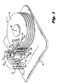
- FIG. 1 there is illustrated a rotary disk memory drive comprising a magnetic disk assembly 1 having individual disks 1a adapted to be driven by a motor (not shown). Such a magnetic disk assembly will be rotated at a constant speed.
- the actuator structure of this invention is part of a major functional assembly in a disk drive, here depicted as a rotary disk drive, which comprises a magnetic head suspension assembly 3, an actuator structure in the form of a rotary actuator bearing housing 5, and a magnetic drive 7.
- the rotary actuator bearing housing 5 is journalled on a spindle 6 which is attached to a base plate 9.
- Other structural features of this disk drive believed not to be essential to an understanding of this invention are not illustrated in the interest of simplicity.
- the actuator bearing housing 5 is provided with two columns 5a and 5b of mounting pads which mount the individual magnetic head suspensions 3. These two columns are slotted laterally in the same plane in plane positions intermediate the planes of the memory disks of the disk assembly 1.
- the confronting faces of these mounting pads that is the width of the individual slots, is sufficient to receive two magnetic head suspension assemblies 3 in back-to-back relationship as seen in Fig. 2.
- the fit is a sliding fit providing a slight friction interference.
- the magnetic head suspension assemblies 3 position the magnetic heads between the disks.
- the flexures and the magnetic heads mounted thereon are not shown in this illustration in the interest of simplicity, however in Fig. 3, one such magnetic head suspension assembly is illustrated.
- the actuator bearing housing 5 comprises a cylindrical body 5d.
- the cylindrical body 5d is provided with a bearing bore 5f in which the bearing assembly (not shown) on the spindle 6 is adhesively fixed.
- Each integrated arm and flexure assembly comprises a flexure 3b and an arm 3d.
- the assembly shown in Fig. 3 is for a downwardly facing head.
- the arm 3d is provided with a pad 3k which as viewed is displaced downwardly from the surface of the remaining portion of the arm.
- the flexure, or load beam 3b is attached to the bottom face of the pad 3k and is preferably secured thereto by means of laser spot welding.
- Dimensional stability in the remaining portion of the arm 3d together with structural rigidity is achieved by displacing the central portion 3m of the mounting face 31.
- a dimple 3n is displaced upwardly from the face 31 of the arm 3d.
- the magnetic head suspension assemblies for the upward facing and downward facing magnetic heads are as shown in Fig.
- the individual pads of the columns 5a and 5b are attached to the cylindrical body 5d of the actuator bearing housing by means of cantilever webs 5c, which, except for the center-most of these webs, are deflectable.
- Bolts 5e extending through axially aligned holes in the pads in the columns of pads 5a and 5b when tightened apply pressure longitudinally of the columns of the pad in each column.
- the longitudinal bolt force displaces the pads longitudinally of the columns in a direction towards the center-most pads. This deflects the cantilever webs 5c which attach the pads to the actuator bearing housing 5d.
- the inner ends of the magnetic head suspension assemblies are securely clamped between the pad faces to the cylindrical body of the actuator bearing housing.
- alignment rods Prior to tightening of the bolts 5e, alignment rods (not shown) are inserted through the corresponding holes 3c which are in the flexures 3b and the arms 3d. This precisely aligns the magnetic head suspension assemblies minimizing, if not completely eliminating, unwanted relative lateral and longitudinal displacement of the magnetic heads during assembly, providing precise magnetic head alignment when the bolts 5e are tightened and the assembly completed, at which time the alignment rods are removed. This provides improved mounting tolerances for the arms since the outer pads will be forced towards the stiffer central pad.
- the cantilever sections provide flexibility for clamping but high stiffness longitudinally of the arms. High longitudinal stiffness is required for high performance disk drive actuators whether of the rotary or linear type.
- the hub is made from stainless steel using a metal injection molding process which is well known. Only a small amount of additional machining is required after molding to cut the slots in the pad columns to define the individual pads and to ream the bearing bore 5f. Since the flexure 5b and the arm 5d are of stainless steel, stainless steel is also used in the hub to provide a thermal expansion coefficient match throughout the head suspension assembly and with the bearing assembly. Thermal expansion mismatches over a period of time are a leading cause of disk drive head misalignment and resulting head tracking errors.
- the actuator rotor 7b is secured to the actuator bearing assembly 5 in a position diametrically opposite to that of the mounting pads of columns 5a and 5b.
- the rotor 7b swings in an arc about the axis of the spindle 6 between the confronting faces of the arcuate permanent magnets 7e and 7f.
- the rotor 7b comprises a bobbin 7c within which a coil (not shown) is wound. The coil is sealed within the bobbin 7c by means of a peripheral enclosure 7d.
- the direction of movement of the rotor 7b between the arcuate permanent magnets 7e and 7f is controlled by the application of direct current to the coil of one polarity or the reverse.
- Stainless steel may also be advantageously employed in such a linear actuator structure to minimize differences in thermal expansion coefficients which are detrimental to magnetic head positioning.
- This actuator structure as part of a magnetic head suspension assembly is generally useful in all disk memory drives whether of the rotary or linear actuator type.
Landscapes
- Moving Of Heads (AREA)
- Supporting Of Heads In Record-Carrier Devices (AREA)
- Reciprocating, Oscillating Or Vibrating Motors (AREA)
Applications Claiming Priority (2)
| Application Number | Priority Date | Filing Date | Title |
|---|---|---|---|
| US434662 | 1989-11-13 | ||
| US07/434,662 US4994931A (en) | 1989-11-13 | 1989-11-13 | Actuator structure for a magnetic head suspension assembly in a disk drive |
Publications (3)
| Publication Number | Publication Date |
|---|---|
| EP0428288A2 true EP0428288A2 (fr) | 1991-05-22 |
| EP0428288A3 EP0428288A3 (en) | 1991-09-11 |
| EP0428288B1 EP0428288B1 (fr) | 1995-08-16 |
Family
ID=23725140
Family Applications (1)
| Application Number | Title | Priority Date | Filing Date |
|---|---|---|---|
| EP90311841A Expired - Lifetime EP0428288B1 (fr) | 1989-11-13 | 1990-10-29 | Structure d'un actionneur pour un ensemble de suspension pour une tête magnétique dans un entraînement à disque |
Country Status (6)
| Country | Link |
|---|---|
| US (1) | US4994931A (fr) |
| EP (1) | EP0428288B1 (fr) |
| JP (1) | JPH03173977A (fr) |
| BR (1) | BR9004735A (fr) |
| CA (1) | CA2021909C (fr) |
| DE (1) | DE69021688T2 (fr) |
Cited By (1)
| Publication number | Priority date | Publication date | Assignee | Title |
|---|---|---|---|---|
| CN100369118C (zh) * | 2003-10-06 | 2008-02-13 | Tdk株式会社 | 头支撑机构、头臂组件以及具有所述头臂组件的盘驱动设备 |
Families Citing this family (25)
| Publication number | Priority date | Publication date | Assignee | Title |
|---|---|---|---|---|
| US5184265A (en) * | 1989-11-13 | 1993-02-02 | Hewlett-Packard Company | Magnetic head suspension assembly in a disk drive |
| US6600631B1 (en) * | 1989-11-27 | 2003-07-29 | Censtor Corp. | Transducer/flexure/conductor structure for electromagnetic read/write system |
| US5062018A (en) * | 1990-04-05 | 1991-10-29 | Seagate Technology, Inc. | Swaged head arm mounting arrangement for disc drives using shape memory alloy |
| US5461525A (en) * | 1990-09-14 | 1995-10-24 | Hutchinson Technology Incorporated | Load beam having areas of varying thickness in the spring region formed by varying numbers of lamina |
| US5193037A (en) * | 1990-11-07 | 1993-03-09 | Areal Technology, Inc. | Compact disk drive for use with laptop computer |
| US5161077A (en) * | 1990-11-09 | 1992-11-03 | Seagate Technology, Inc. | Actuator arm with a steel sleeve for thermal off track compensation |
| JPH04255977A (ja) * | 1991-02-08 | 1992-09-10 | Nec Corp | 磁気ディスク装置 |
| US5267110A (en) * | 1991-03-19 | 1993-11-30 | International Business Machines Corporation | Rotary actuator for a direct access storage device |
| JP3089360B2 (ja) * | 1991-05-29 | 2000-09-18 | ハッチンソン テクノロジー インコーポレイテッド | 薄形ヘッドディスクアッセンブリ |
| US5251085A (en) * | 1991-07-17 | 1993-10-05 | Maxtor Corporation | Pivotable arm assembly with reduced thermal distortion |
| US5381289A (en) * | 1993-02-26 | 1995-01-10 | Hutchinson Technology Incorporated | Suspension for in-line offset head mounting |
| JP2553316B2 (ja) * | 1993-03-02 | 1996-11-13 | インターナショナル・ビジネス・マシーンズ・コーポレイション | データ記憶ディスク・ドライブ装置 |
| JP3243543B2 (ja) * | 1993-06-30 | 2002-01-07 | 株式会社日立製作所 | 磁気ディスク記憶装置 |
| WO1995013610A1 (fr) * | 1993-11-12 | 1995-05-18 | Conner Peripherals, Inc. | Ensemble actionneur empilable |
| US6229677B1 (en) | 1993-11-12 | 2001-05-08 | Seagate Technology Llc | Disc drive actuator arm assembly with outer arm z-height less than inner arm z-height |
| US6313970B1 (en) * | 1994-02-18 | 2001-11-06 | Maxtor Corporation | Disk drive with low profile suspension assemblies |
| US5382851A (en) * | 1994-05-04 | 1995-01-17 | Xolox Corporation | Swing-type actuator |
| JP3344683B2 (ja) * | 1995-06-07 | 2002-11-11 | インターナショナル・ビジネス・マシーンズ・コーポレーション | アクチュエータ・アセンブリ及びデータ記憶システム |
| US6121742A (en) * | 1998-03-20 | 2000-09-19 | Seagate Technology Llc | Control scheme for multi-actuator disc drive |
| CN1508793A (zh) * | 2002-12-12 | 2004-06-30 | ���µ�����ҵ��ʽ���� | 头支承装置及其驱动方法和采用它的盘装置 |
| US20040123440A1 (en) * | 2002-12-30 | 2004-07-01 | Christopher Nguyen | Methods for assembling or reworking a rotary actuator assembly for a media data storage device |
| US6989970B2 (en) * | 2002-12-27 | 2006-01-24 | Matsushita Electric Industrial Co., Ltd. | Rotary actuator assembly for a rotatable media data storage device |
| US7031117B2 (en) * | 2002-12-30 | 2006-04-18 | Matsushita Electrical Industrial Co., Ltd. | Modular rotary actuator assembly for a rotatable media data storage device |
| US20040123448A1 (en) * | 2002-12-30 | 2004-07-01 | Christopher Nguyen | Methods for assembling or reworking a modular rotary actuator assembly for a rotatable media data storage device |
| JP3895725B2 (ja) * | 2003-12-26 | 2007-03-22 | アルプス電気株式会社 | ディスク装置 |
Family Cites Families (10)
| Publication number | Priority date | Publication date | Assignee | Title |
|---|---|---|---|---|
| US4131921A (en) * | 1977-04-15 | 1978-12-26 | Okidata Corporation | Head positioning system for disc files |
| US4116284A (en) * | 1977-06-10 | 1978-09-26 | Cox Van R | Earth drills |
| SU696536A1 (ru) * | 1978-05-31 | 1979-11-05 | Предприятие П/Я А-3103 | Устройство дл перемещени магнитных головок |
| SU769616A1 (ru) * | 1978-10-09 | 1980-10-07 | Предприятие П/Я А-3103 | Устройство дл определени положени магнитных головок относительно магнитного диска |
| JPS5823362A (ja) * | 1981-07-30 | 1983-02-12 | Nippon Telegr & Teleph Corp <Ntt> | 揺動アクチユエ−タ |
| US4571649A (en) * | 1982-08-18 | 1986-02-18 | Magnetic Peripherals, Inc. | Disk drive carriage structure |
| DE3404231A1 (de) * | 1984-02-07 | 1985-08-08 | Siemens AG, 1000 Berlin und 8000 München | Positioniereinrichtung fuer einen magnetplattenspeicher |
| DE8519878U1 (de) * | 1985-07-10 | 1985-10-17 | Basf Ag, 6700 Ludwigshafen | Vorrichtung zum Positionieren von Gegenständen geringer Masse insbesondere von mindestens einem Magnetkopf, in bezug auf einen zweiten Gegenstand, insbesondere auf mindestens eines Magnetplatte |
| US4716482A (en) * | 1986-02-14 | 1987-12-29 | Hewlett-Packard Company | Head actuator limit stop assembly for a disk memory drive |
| US4716478A (en) * | 1986-02-14 | 1987-12-29 | Hewlett-Packard Company | Two point attachment with single point clamping for connecting the arm stack to the actuator member in a disc memory drive |
-
1989
- 1989-11-13 US US07/434,662 patent/US4994931A/en not_active Expired - Fee Related
-
1990
- 1990-07-25 CA CA002021909A patent/CA2021909C/fr not_active Expired - Fee Related
- 1990-09-18 BR BR909004735A patent/BR9004735A/pt not_active Application Discontinuation
- 1990-10-29 EP EP90311841A patent/EP0428288B1/fr not_active Expired - Lifetime
- 1990-10-29 DE DE69021688T patent/DE69021688T2/de not_active Expired - Fee Related
- 1990-11-13 JP JP2306949A patent/JPH03173977A/ja active Pending
Cited By (1)
| Publication number | Priority date | Publication date | Assignee | Title |
|---|---|---|---|---|
| CN100369118C (zh) * | 2003-10-06 | 2008-02-13 | Tdk株式会社 | 头支撑机构、头臂组件以及具有所述头臂组件的盘驱动设备 |
Also Published As
| Publication number | Publication date |
|---|---|
| BR9004735A (pt) | 1991-09-10 |
| EP0428288A3 (en) | 1991-09-11 |
| EP0428288B1 (fr) | 1995-08-16 |
| US4994931A (en) | 1991-02-19 |
| DE69021688T2 (de) | 1996-01-25 |
| CA2021909A1 (fr) | 1991-05-14 |
| DE69021688D1 (de) | 1995-09-21 |
| JPH03173977A (ja) | 1991-07-29 |
| CA2021909C (fr) | 1994-09-06 |
Similar Documents
| Publication | Publication Date | Title |
|---|---|---|
| US4994931A (en) | Actuator structure for a magnetic head suspension assembly in a disk drive | |
| US5184265A (en) | Magnetic head suspension assembly in a disk drive | |
| US4247794A (en) | Linear actuator | |
| JP3933762B2 (ja) | ヘッドアクチュエータ及びディスク装置 | |
| JPH0628647A (ja) | 多重トラック方式のテープレコーダ用ヘッド位置合わせ機構 | |
| EP0750780A1 (fr) | Lecture et ecriture d'informations sur un support d'enregistrement | |
| US4775908A (en) | Moving magnet actuator | |
| US5291360A (en) | Head suspension assembly for a disk drive | |
| CA2021359C (fr) | Suspension de tete magnetique de lecteur de disques | |
| JPS5835030B2 (ja) | 並列コイル型作動装置 | |
| KR930011446B1 (ko) | 트랜스듀우서 구동장치 | |
| US5363262A (en) | Disk drive having an improved transducer suspension assembly | |
| US4399477A (en) | Split band actuator | |
| US4868696A (en) | Linear actuator using a compound parallel bendable element suspension system | |
| US6407888B1 (en) | Transverse slot mounting of head/gimbal suspension assemblies in disc drives | |
| US6304420B1 (en) | Preloaded gimbal in a head suspension for limiting head/disc separation | |
| JP2002093086A (ja) | 磁気ディスク装置 | |
| JP3706020B2 (ja) | 磁気ディスクドライブのためのヘッド浮遊組立体 | |
| US4751597A (en) | Center of percussion head actuator assembly | |
| US5710680A (en) | Magnetic hard disk drive head suspension apparatus | |
| EP0078911B1 (fr) | Patin flottant sur coussin d'air pour tête magnétique et mécanisme d'actionnement électromagnétique | |
| JPH0823976B2 (ja) | 磁気記録再生装置 | |
| EP0432877B1 (fr) | Actuateur rotatif de têtes pour un dispositif de stockage de données d'un entraînement à disque magnétique | |
| JP2730250B2 (ja) | トランスジューサの位置決め装置 | |
| EP0285867B1 (fr) | Positionneur linéaire utilisant un système de suspension comprenant des éléments assemblés parallèlement et susceptibles d'être courbés |
Legal Events
| Date | Code | Title | Description |
|---|---|---|---|
| PUAI | Public reference made under article 153(3) epc to a published international application that has entered the european phase |
Free format text: ORIGINAL CODE: 0009012 |
|
| AK | Designated contracting states |
Kind code of ref document: A2 Designated state(s): DE FR GB IT |
|
| PUAL | Search report despatched |
Free format text: ORIGINAL CODE: 0009013 |
|
| AK | Designated contracting states |
Kind code of ref document: A3 Designated state(s): DE FR GB IT |
|
| 17P | Request for examination filed |
Effective date: 19920217 |
|
| 17Q | First examination report despatched |
Effective date: 19940330 |
|
| GRAA | (expected) grant |
Free format text: ORIGINAL CODE: 0009210 |
|
| ITF | It: translation for a ep patent filed | ||
| AK | Designated contracting states |
Kind code of ref document: B1 Designated state(s): DE FR GB IT |
|
| REF | Corresponds to: |
Ref document number: 69021688 Country of ref document: DE Date of ref document: 19950921 |
|
| ET | Fr: translation filed | ||
| PLBE | No opposition filed within time limit |
Free format text: ORIGINAL CODE: 0009261 |
|
| STAA | Information on the status of an ep patent application or granted ep patent |
Free format text: STATUS: NO OPPOSITION FILED WITHIN TIME LIMIT |
|
| 26N | No opposition filed | ||
| PGFP | Annual fee paid to national office [announced via postgrant information from national office to epo] |
Ref country code: FR Payment date: 19960913 Year of fee payment: 7 |
|
| PGFP | Annual fee paid to national office [announced via postgrant information from national office to epo] |
Ref country code: DE Payment date: 19960917 Year of fee payment: 7 |
|
| PGFP | Annual fee paid to national office [announced via postgrant information from national office to epo] |
Ref country code: GB Payment date: 19960925 Year of fee payment: 7 |
|
| PG25 | Lapsed in a contracting state [announced via postgrant information from national office to epo] |
Ref country code: GB Free format text: LAPSE BECAUSE OF NON-PAYMENT OF DUE FEES Effective date: 19971029 |
|
| PG25 | Lapsed in a contracting state [announced via postgrant information from national office to epo] |
Ref country code: FR Free format text: THE PATENT HAS BEEN ANNULLED BY A DECISION OF A NATIONAL AUTHORITY Effective date: 19971031 |
|
| GBPC | Gb: european patent ceased through non-payment of renewal fee |
Effective date: 19971029 |
|
| PG25 | Lapsed in a contracting state [announced via postgrant information from national office to epo] |
Ref country code: DE Free format text: LAPSE BECAUSE OF NON-PAYMENT OF DUE FEES Effective date: 19980701 |
|
| REG | Reference to a national code |
Ref country code: FR Ref legal event code: ST |
|
| PG25 | Lapsed in a contracting state [announced via postgrant information from national office to epo] |
Ref country code: IT Free format text: LAPSE BECAUSE OF NON-PAYMENT OF DUE FEES;WARNING: LAPSES OF ITALIAN PATENTS WITH EFFECTIVE DATE BEFORE 2007 MAY HAVE OCCURRED AT ANY TIME BEFORE 2007. THE CORRECT EFFECTIVE DATE MAY BE DIFFERENT FROM THE ONE RECORDED. Effective date: 20051029 |