EP0428321A2 - Supports d'enregistrement magnéto-optique et appareil - Google Patents
Supports d'enregistrement magnéto-optique et appareil Download PDFInfo
- Publication number
- EP0428321A2 EP0428321A2 EP90312172A EP90312172A EP0428321A2 EP 0428321 A2 EP0428321 A2 EP 0428321A2 EP 90312172 A EP90312172 A EP 90312172A EP 90312172 A EP90312172 A EP 90312172A EP 0428321 A2 EP0428321 A2 EP 0428321A2
- Authority
- EP
- European Patent Office
- Prior art keywords
- magnetic layer
- magnetic
- magneto
- optical recording
- recording medium
- Prior art date
- Legal status (The legal status is an assumption and is not a legal conclusion. Google has not performed a legal analysis and makes no representation as to the accuracy of the status listed.)
- Granted
Links
Images




Classifications
-
- G—PHYSICS
- G11—INFORMATION STORAGE
- G11B—INFORMATION STORAGE BASED ON RELATIVE MOVEMENT BETWEEN RECORD CARRIER AND TRANSDUCER
- G11B11/00—Recording on or reproducing from the same record carrier wherein for these two operations the methods are covered by different main groups of groups G11B3/00 - G11B7/00 or by different subgroups of group G11B9/00; Record carriers therefor
- G11B11/10—Recording on or reproducing from the same record carrier wherein for these two operations the methods are covered by different main groups of groups G11B3/00 - G11B7/00 or by different subgroups of group G11B9/00; Record carriers therefor using recording by magnetic means or other means for magnetisation or demagnetisation of a record carrier, e.g. light induced spin magnetisation; Demagnetisation by thermal or stress means in the presence or not of an orienting magnetic field
- G11B11/105—Recording on or reproducing from the same record carrier wherein for these two operations the methods are covered by different main groups of groups G11B3/00 - G11B7/00 or by different subgroups of group G11B9/00; Record carriers therefor using recording by magnetic means or other means for magnetisation or demagnetisation of a record carrier, e.g. light induced spin magnetisation; Demagnetisation by thermal or stress means in the presence or not of an orienting magnetic field using a beam of light or a magnetic field for recording by change of magnetisation and a beam of light for reproducing, i.e. magneto-optical, e.g. light-induced thermomagnetic recording, spin magnetisation recording, Kerr or Faraday effect reproducing
- G11B11/10582—Record carriers characterised by the selection of the material or by the structure or form
- G11B11/10586—Record carriers characterised by the selection of the material or by the structure or form characterised by the selection of the material
-
- G—PHYSICS
- G11—INFORMATION STORAGE
- G11B—INFORMATION STORAGE BASED ON RELATIVE MOVEMENT BETWEEN RECORD CARRIER AND TRANSDUCER
- G11B11/00—Recording on or reproducing from the same record carrier wherein for these two operations the methods are covered by different main groups of groups G11B3/00 - G11B7/00 or by different subgroups of group G11B9/00; Record carriers therefor
- G11B11/10—Recording on or reproducing from the same record carrier wherein for these two operations the methods are covered by different main groups of groups G11B3/00 - G11B7/00 or by different subgroups of group G11B9/00; Record carriers therefor using recording by magnetic means or other means for magnetisation or demagnetisation of a record carrier, e.g. light induced spin magnetisation; Demagnetisation by thermal or stress means in the presence or not of an orienting magnetic field
- G11B11/105—Recording on or reproducing from the same record carrier wherein for these two operations the methods are covered by different main groups of groups G11B3/00 - G11B7/00 or by different subgroups of group G11B9/00; Record carriers therefor using recording by magnetic means or other means for magnetisation or demagnetisation of a record carrier, e.g. light induced spin magnetisation; Demagnetisation by thermal or stress means in the presence or not of an orienting magnetic field using a beam of light or a magnetic field for recording by change of magnetisation and a beam of light for reproducing, i.e. magneto-optical, e.g. light-induced thermomagnetic recording, spin magnetisation recording, Kerr or Faraday effect reproducing
- G11B11/10502—Recording on or reproducing from the same record carrier wherein for these two operations the methods are covered by different main groups of groups G11B3/00 - G11B7/00 or by different subgroups of group G11B9/00; Record carriers therefor using recording by magnetic means or other means for magnetisation or demagnetisation of a record carrier, e.g. light induced spin magnetisation; Demagnetisation by thermal or stress means in the presence or not of an orienting magnetic field using a beam of light or a magnetic field for recording by change of magnetisation and a beam of light for reproducing, i.e. magneto-optical, e.g. light-induced thermomagnetic recording, spin magnetisation recording, Kerr or Faraday effect reproducing characterised by the transducing operation to be executed
- G11B11/10504—Recording
- G11B11/10506—Recording by modulating only the light beam of the transducer
-
- G—PHYSICS
- G11—INFORMATION STORAGE
- G11B—INFORMATION STORAGE BASED ON RELATIVE MOVEMENT BETWEEN RECORD CARRIER AND TRANSDUCER
- G11B11/00—Recording on or reproducing from the same record carrier wherein for these two operations the methods are covered by different main groups of groups G11B3/00 - G11B7/00 or by different subgroups of group G11B9/00; Record carriers therefor
- G11B11/10—Recording on or reproducing from the same record carrier wherein for these two operations the methods are covered by different main groups of groups G11B3/00 - G11B7/00 or by different subgroups of group G11B9/00; Record carriers therefor using recording by magnetic means or other means for magnetisation or demagnetisation of a record carrier, e.g. light induced spin magnetisation; Demagnetisation by thermal or stress means in the presence or not of an orienting magnetic field
- G11B11/105—Recording on or reproducing from the same record carrier wherein for these two operations the methods are covered by different main groups of groups G11B3/00 - G11B7/00 or by different subgroups of group G11B9/00; Record carriers therefor using recording by magnetic means or other means for magnetisation or demagnetisation of a record carrier, e.g. light induced spin magnetisation; Demagnetisation by thermal or stress means in the presence or not of an orienting magnetic field using a beam of light or a magnetic field for recording by change of magnetisation and a beam of light for reproducing, i.e. magneto-optical, e.g. light-induced thermomagnetic recording, spin magnetisation recording, Kerr or Faraday effect reproducing
- G11B11/10502—Recording on or reproducing from the same record carrier wherein for these two operations the methods are covered by different main groups of groups G11B3/00 - G11B7/00 or by different subgroups of group G11B9/00; Record carriers therefor using recording by magnetic means or other means for magnetisation or demagnetisation of a record carrier, e.g. light induced spin magnetisation; Demagnetisation by thermal or stress means in the presence or not of an orienting magnetic field using a beam of light or a magnetic field for recording by change of magnetisation and a beam of light for reproducing, i.e. magneto-optical, e.g. light-induced thermomagnetic recording, spin magnetisation recording, Kerr or Faraday effect reproducing characterised by the transducing operation to be executed
- G11B11/10517—Overwriting or erasing
- G11B11/10519—Direct overwriting, i.e. performing erasing and recording using the same transducing means
- G11B11/10521—Direct overwriting, i.e. performing erasing and recording using the same transducing means using a single light spot
Definitions
- This invention relates to magneto-optical recording media that are overwritable by optical modulation, and apparatus utizing such media.
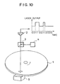
- Fig.10 shows a structure of a magneto-optical recording apparatus as previously proposed by the present applicants.
- 1 is a magneto-optical recording medium
- 2 is a semiconductor laser
- 3 is a beam splitter
- 4 is a reproducing apparatus
- 5 is an external magnetic field generating device.
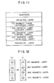
- the structure of the magneto-optical recording medium in the invention of our earlier application is also shown in Fig. 11.
- the following, for example, are formed on a substrate by a method such as sputtering: Dielectric layer: SiN x 650 angstroms First magnetic layer: Tb22Fe69Co9 800 angstroms Second magnetic layer: Gd8Dy17Fe60Co15 1500 angstroms Third magnetic layer: Tb16Fe84 200 angstroms Fourth magnetic layer: Tb30Co70 400 angstroms Protective layer: SiN x 700 angstroms Adjacent magnetic layers are here coupled by exchange forces.
- the first magnetic layer is the recording layer for recording and storing information.
- the second magnetic layer, third magnetic layer, and fourth magnetic layer do not function as information media but are additional layers that enable direct overwriting by optical modulation.
- the fourth magnetic layer is an initializing layer, the sublattice magnetization of which does not reverse under heating due to laser illumination within the operating range and acts in opposition to the bias magnetic field.
- the third magnetic layer is a control layer for shielding the exchange force from the fourth magnetic layer at high temperatures.
- the recording medium After formation of the layers of the magneto-optical recording medium, out of the 24 sublattice magnetic moment configurations, the recording medium is put first and once only into the two magnetization states shown in Fig. 12 in which the magnetic moments of the transition-metal (TM) sublattices of the second magnetic layer, the third magnetic layer, and the fourth magnetic layer point down. After recording, these two states will be the recorded states.
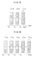
- Outlined arrows in the drawings will hereinafter indicate magnetization, arrows appearing therewithin or alone will indicate the magnetic moment of the transition-metal sublattice, dottted line will indicate the state in which a magnetic wall exists between magnetic layers, and a horizontal line will indicate the state of heating above the Curie temperature, in which ferromagnetization is lost.
- the bias magnetic field Hb is generated so that in the vicinity of the Curie temperature, the sublattice magnetization direction of the second magnetic layer opposes the magnetization orientation of the fourth magnetic layer. If the fourth magnetic layer is oriented in the down direction, accordingly, then the orientation will be upward if it comprises a magnetic material having a compensation temperature below the Curie temperature, and downward if it comprises a magnetic material not having a compensation temperature below the Curie temperature. In this embodiment it is generated in the upward direction.
- magnetization will hereinafter denote the magnetization of the transition-metal sublattice.
- the magnetization direction of the second magnetic layer remains unchanged, and the magnetization of the second magnetic layer is transferred to the first magnetic layer, so the first magnetic layer becomes magnetized in the down direction.
- the third magnetic layer and the fourth magnetic layer play no particular role in this process, and even if the magnetization of the third magnetic layer is lost, it is magnetized in the same direction again by the exchange coupling with the fourth magnetic layer, giving the initial "0" state.
- the first magnetic layer and third magnetic layer are demagnetized, but the magnetization direction of the fourth magnetic layer does not change.
- the second magnetic layer receives no exchange forces from the first magnetic layer and the third magnetic layer, but is magnetized by the external magnetic field in the up direction.
- the magnetization of the second magnetic layer is transferred to the first magnetic layer and the first magnetic layer becomes magnetized in the up direction.
- the magnetization of the third magnetic layer aligns with the fourth magnetic layer in the down direction, then the temperature falls further, and the magnetization of the second magnetic layer aligns with the magnetization of the fourth magnetic layer via the third magnetic layer, in the down direction, giving the initial "1" state.
- optically modulated direct overwriting is possible by modulating only the laser light intensity.
- Another problem is that the external magnetic field generating device is disposed on the opposite side of the magneto-optical recording medium from the optical head. If double-sided media are used, it is not possible to place the optical head on the opposite side of the magneto-optical recording medium.
- a magneto-optical recording medium is for use in a system for recording information with bits having upward magnetization and having downward magnetization on a recording layer of the magneto-optical recording medium, and comprises: a first magnetic layer with perpendicular magnetic anisotropy, a second magnetic layer disposed on this first magnetic layer and coupled to said first magnetic layer by an exchange force, a third magnetic layer disposed on this second magnetic layer and coupled to said second magnetic layer by an exchange force, and a fourth magnetic layer disposed on this third magnetic layer and coupled to said third magnetic layer by an exchange force; said magneto-optical recording medium satisfying: Tc4 > Tc1, Tc4 > Tc3, Tc2 > Tc1, and Tc2 > Tc3, the magnetization of the first magnetic layer being not reversed by magnetic reversal of the second magnetic layer at room temperature, wherein the sublattice magnetization directions of the second magnetic layer, the third magnetic layer, and the fourth magnetic layer are initialized so as to be aligned in the up direction or the down direction at room temperature after recording
- the second magnetic layer preferably comprises a layer of magnetic material having a compensation temperature below its Curie temperature
- the fourth magnetic layer preferably comprises a layer a magnetic material of which the magnetization existing in the same direction as the transition-metal sublattice magnetization is reduced as the temperature rises.
- the second magnetic layer perferably comprises a layer of magnetic material the rare-earth (RE) sublattice magnetization of which is dominant at room temperature and which does not have a compensation temperature
- the fourth magnetic layer is preferably formed of a magnetic material of which the magnetization existing in the same direction as the rare-earth sublattice magnetization is reduced as the temperature rises.
- magneto-optical recording medium is adhesively joined to a read-only optical recording medium, or a write-once optical recording medium, thereby to form a composite recording medium.
- a magneto-optical recording system is for recording information with bits having upward magnetization and having downward magnetization on a recording layer of a magneto-optical recording medium, and comprises: a magneto-optical recording medium as recited above; a means for directing a laser beam onto the medium; and a means for modulating said beam to heat said magneto-optical recording medium to at least two values according to binary information to be recorded; wherein the sublattice magnetization directions of the second magnetic layer, the third magnetic layer, and the fourth magnetic layer are initialized so as to be aligned in the up direction or the down direction at room temperature after recording, and under illumination by a laser beam that heats said magneto-optical medium to the higher temperature of said two laser beam values, a stray magnetic field generated by said magneto-optical recording medium acts so that the sublattice magnetization direction of the second magnetic layer is recorded in the direction opposite to said initialization direction.
- a magneto-optical recording system for recording information with bits having upward magnetization and having downward magnetization on a recording layer of a magneto-optical recording medium, having four magnetic layers exchange-coupled with each other.
- a laser beam directed onto the medium is modulated to heat the magneto-optical recording medium to two values, for "High” writing and for "Low” writing.
- the first to third layers lose magnetization because their Curie temperatures are exceeded, and upon cooling, the second layer is magnetized by a stray magnetic mainly consisting of the magnetic field from the fourth layer.
- the magnetization of the second layer is transferred to the first layer when the first layers cools below its Curie temperature, by exchange coupling.
- the magnetization of the second layer is reversed due to exchange coupling from the fourth layer through the third layer, to which the magnetization of the first magnetization is transferred, when the third layer cools below its Curie temperature.
- the direction of magnetization of the second layer as determined by the exchange coupling is opposite to the direction of the magnetization as determined by the stray magnetic field.
- the first layer is not reversed due to its high coercivity.
- the first layer attains magnetization in a first direction.
- the first and the third layers lose their magnetization as their Curie temperatures are exceeded, but the second layer does not lose its magnetisation, and its magnetization is retained, and transferred to the first layer when the first layer cools, so the first layer attains a magnetization in the second direction, opposite to the first direction.
- Fig. 1 shows a sectional view of a magneto-optical recording medium of a first embodiment of this invention, which is identical to the prior-art example except for the fourth magnetic layer, and which has similar functions caused by exchange forces for low-temperature operation.
- the recording medium comprises, for example, the following, formed on a glass substrate by a process such as sputtering.
- Dielectric layer SiN x 650 angstroms
- First magnetic layer Tb22Fe69Co9 800 angstroms
- Second magnetic layer Gd8Dy17Fe60Co15 1500 angstroms
- Third magnetic layer Tb16Fe84 200 angstroms
- Fourth magnetic layer Tb20Co80 800 angstroms
- Protective layer SiN x 700 angstroms
- Adjacent magnetic layers are here coupled by exchange forces.
- the first, third and fourth magnetic layers are TM rich, while the second magnetic layer is RE rich below its compensation temperature which is close to the Tc1, but is TM rich above the compensation temperature.
- the fourth magnetic layer is an orientation layer having an exchange force that opposes the magnetostatic coupling force from the initializing layer.
- the initialization process after formation of the layers of the magneto-optical recording medium is the same as in the prior-art example. No external magnetic field is needed, because its function is added to the orientation layer.
- the first magnetic layer and the third magnetic layer are demagnetized, but the magnetization direction of the fourth magnetic layer does not change.
- the second magnetic layer receives no exchange forces from the first magnetic layer and the third magnetic layer, but is magnetized in the up direction by stray magnetic field, mainly consisting of magnetostatic coupling with the fourth magnetic layer.
- stray magnetic field mainly consisting of magnetostatic coupling with the fourth magnetic layer.
- Other contribution of the stray magnetic field which acts on the second magnetic layer is a leakage magnetic flux from the neighboring regions of the same second magnetic layer.
- the magnetization of the second magnetic layer is transferred to the first magnetic layer and the first magnetic layer becomes magnetized in the up direction.
- the magnetization of the third magnetic layer aligns with the fourth magnetic layer in the down direction
- the magnetization of the second magnetic layer aligns with the magnetization of the fourth magnetic layer via the third magnetic layer, in the down direction, giving the initial "1" state.
- a feature of this invention is that it makes use of magnetostatic coupling with the fourth magnetic layer.
- the magnetization distribution of the fourth magnetic layer is as in Fig. 3, creating in effect an upwardly oriented magnetic field.
- Tables 1 and 2 show embodiments 2 to 6.
- Using four-element RF magnetron sputtering apparatus one places an Fe target having Tb and Co chips, an Fe target having Gd and Co chips, an Fe target having Tb chips, and a Co target having Tb chips, and sets in the chamber of the apparatus a glass substrate 1.2mm thick and 86mm in diameter, that is pregrooved at a 1.6 ⁇ m pitch.
- the lower table indicates the recording and reproduction characteristics of a 0.76 ⁇ m bit-length signal on a 2 ⁇ m bit-length signal under linear velocity conditions of 11m/sec for various numbers of chips on the targets and for various sputtering times. Direct overwriting was confirmed in this case with no observed remanent unerased signal.
- Each of the magnetic layers here may itself comprise multiple sublayers: for example, before the first magnetic layer is formed, an exchange-coupled magnetic layer with a large magneto-optic effect may be provided.
- An improvement in CNR by 1dB was observed when the following were formed on a glass substrate by a method such as sputtering: Dielectric layer: SiN x 650 angstroms Reproduction layer: Tb15Fe70Co15 100 angstroms First magnetic layer: Tb22Fe69Co9 800 angstroms Second magnetic layer: Gd8Dy17Fe60Co15 1500 angstroms Third magnetic layer: Tb16Fe84 200 angstroms Fourth magnetic layer: Tb20Co80 800 angstroms Protective layer: SiN x 700 angstroms
- Magnetic layers, dielectric layers, oxide layers, and the like can also be created between the magnetic layers to control the exchange forces.
- the magnetic layers may also comprise ferrimagnetic materials such as GdFe, GdTbFeCo, TbDyFeCo, NdDyFeCo, DyCo, TbHoFeCo, and DyHoCo.
- Two single-sided media were adhesively joined by a two-part epoxy-based resin.
- magneto-optical recording media of the first embodiment were joined together, for example, in a magneto-optical recording medium with a protective layer, a CN ratio of 45dB, with no remanent unerased signal, was obtained by optical modulation of a 0.76 ⁇ m bit-length signal on a 2 ⁇ m bit-length signal at a linear velocity of 11m/sec with a peak laser power of 14mW and bottom laser power of 5mW.
- Adhesion may also be accomplished with a thermoplastic resin, thermosetting resin, or the like, and what is joined may be a read-only optical disk, a write-once optical disk, or the like.
- the media may also have shapes other than disk shapes: for example, they may have a card shape or the like.
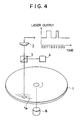
- Fig. 4 shows a structural drawing of a magneto-optical recording apparatus.
- 1 is a magneto-optical recording medium
- 2 is a semiconductor laser
- 3 is a polarizing beam splitter
- 4 is a reproducing apparatus.
- the semiconductor laser is adapted for binary modulation of the beam intensity of the recording laser beam according to the information to be recorded, with output exceeding the laser beam intensity during reproduction.
- the magneto-optical recording medium is in the form of a disk having recording tracks 1a in spiral or circular form, and is rotated about is axis, by a motor 6, so that the disk is moved relative to the laser beam.
- a CN ratio of 45dB, with no remanent unerased signal was obtained by optical modulation of a 0.76 ⁇ m bit-length signal on a 2 ⁇ m bit-length signal at a linear velocity of 11m/sec with a peak laser power of 13mW and bottom laser power of 5 mW.
- Fig. 5 shows a structural drawing of a magneto-optic recording apparatus.
- 1 is a magneto-optical recording medium
- 2 is a semiconductor laser
- 3 is a beam splitter
- 4 is a reproducing apparatus.
- the laser beam emitted by the semiconductor laser can be generated in a pulse pattern suitable for high-temperature operation, comprising a pulse train of twenty times the maximum frequency of the recorded information, and a pulse pattern suitable for low-temperature operation, comprising a pulse train of ten times the maximum frequency of the recorded information. Identical values were employed for respective constituent pulses at this time.
- Fig. 6 shows a structural drawing of a magneto-optical recording apparatus.
- 1 is a magneto-optical recording medium
- 2-1 and 2-2 are semiconductor lasers
- 3 is a polarizing beam splitter
- 4 is a reproducing apparatus
- 5 is a beam splitter.
- the semiconductor lasers 2-1 and 2-2 have a wavelength of 830nm and maximum continuous emitted output of 16mW, and are focused onto adjacent positions on the magneto-optical recording medium.
- One of the lasers generates constant laser output suitable for low-temperature operation, while the other laser generates laser output that attains the temperature necessary for high-temperature operation only for the information "1."
- direct overwriting was possible using the magneto-optical recording medium of embodiment 1 with the maximum laser output on the surface of the recording medium reduced by 3mW, to 10mW.
- Fig. 7 shows a structural drawing of a magneto-optical recording apparatus.
- 1 is a magneto-optical recording medium
- 2-1 and 2-2 are semiconductor lasers
- 3 is a polarizing beam splitter
- 4 is a reproducing apparatus
- 5 is a beam splitter.
- the semiconductor laser 2-1 is for recording, having a wavelength of 830nm and maximum continuous emitted output of 20mW
- 2-2 is for reproducing, having a wavelength of 780nm and maximum continuous emitted output of 4mW, adapted for tracking the laser spot of 2-1, enabling verification to be performed simultaneously with overwriting. In this way data transfer rates during recording were made substantially equal to those during reproducing.
- Fig. 8 shows a structural drawing of a magneto-optical recording apparatus.
- 1 is a magneto-optical recording medium
- 2-1 and 2-2 are identical semiconductor lasers with a wavelength of 830nm and maximum continuous emitted output of 20mW
- 3 is a polarizing beam splitter
- 4 is a reproducing apparatus
- 5 is a beam splitter.
- the laser beams are focused onto adjacent tracks on the magneto-optical recording medium and are adapted for simultaneous recording.
- magneto-optical recording medium is moved, but lasers can also be arranged in an array or matrix for recording and reproduction without moving the magneto-optical recording medium.
- optical element such as a liquid crystal
- the transmittance of which can be spatially varied.
- Fig. 9 shows a structural drawing of a magneto-optical recording apparatus.
- 1 is a magneto-optical medium
- 2-1 and 2-2 are semiconductor lasers disposed on both sides of the optical recording medium
- 3 is a polarizing beam splitter
- 4-1 and 4-2 are reproducing apparatuses.
- the optical recording medium of embodiment 7 is employed as an optical recording medium, and the semiconductor laser 2-2 and reproducing apparatus 4-2 can reproduce read-only optical disks.
- this invention provides the orientation layer with two opposing functions, an exchange force and a magnetostatic coupling force, enabling direct overwriting without any device for generating an external magnetic field.
Applications Claiming Priority (2)
| Application Number | Priority Date | Filing Date | Title |
|---|---|---|---|
| JP296856/89 | 1989-11-14 | ||
| JP1296856A JP2707769B2 (ja) | 1989-11-14 | 1989-11-14 | 光磁気記録媒体及びそれを用いた光磁気記録再生装置 |
Publications (3)
| Publication Number | Publication Date |
|---|---|
| EP0428321A2 true EP0428321A2 (fr) | 1991-05-22 |
| EP0428321A3 EP0428321A3 (en) | 1991-12-18 |
| EP0428321B1 EP0428321B1 (fr) | 1997-01-15 |
Family
ID=17839048
Family Applications (1)
| Application Number | Title | Priority Date | Filing Date |
|---|---|---|---|
| EP90312172A Expired - Lifetime EP0428321B1 (fr) | 1989-11-14 | 1990-11-07 | Supports d'enregistrement magnéto-optique et appareil |
Country Status (4)
| Country | Link |
|---|---|
| US (1) | US5208797A (fr) |
| EP (1) | EP0428321B1 (fr) |
| JP (1) | JP2707769B2 (fr) |
| DE (1) | DE69029709T2 (fr) |
Cited By (3)
| Publication number | Priority date | Publication date | Assignee | Title |
|---|---|---|---|---|
| EP0600698A3 (fr) * | 1992-11-30 | 1994-11-23 | Canon Kk | Milieu d'enregistrement magnéto-optique. |
| EP0645766A1 (fr) * | 1993-09-29 | 1995-03-29 | Sony Corporation | Appareil d'enregistrement et/ou de reproduction pour support d'enregistrement magnétooptique |
| EP0428946B1 (fr) * | 1989-11-14 | 1996-01-31 | Mitsubishi Denki Kabushiki Kaisha | Milieu d'enregistrement magnéto-optique |
Families Citing this family (14)
| Publication number | Priority date | Publication date | Assignee | Title |
|---|---|---|---|---|
| US5361248A (en) * | 1992-06-01 | 1994-11-01 | Eastman Kodak Company | Direct overwrite magneto-optical storage medium not requiring an initialization magnet |
| KR100292604B1 (ko) * | 1992-09-28 | 2001-06-15 | 가나이 쓰도무 | 오버라이트가능한광기록매체및그의기록방법 |
| JPH06131722A (ja) * | 1992-10-16 | 1994-05-13 | Canon Inc | 光磁気記録媒体およびその記録方法 |
| JP3092363B2 (ja) | 1992-12-01 | 2000-09-25 | 松下電器産業株式会社 | 光磁気記録媒体 |
| JP3354726B2 (ja) * | 1994-09-27 | 2002-12-09 | 松下電器産業株式会社 | 光磁気記録媒体及び再生方法 |
| JP3277245B2 (ja) * | 1995-03-27 | 2002-04-22 | 富士通株式会社 | 光磁気記録媒体及びその再生方法 |
| US5717662A (en) * | 1995-05-12 | 1998-02-10 | Canon Kabushiki Kaisha | Super-resolution magneto-optical recording medium using magnetostatic coupling and information reproduction method using the medium |
| JP3445023B2 (ja) * | 1995-06-08 | 2003-09-08 | シャープ株式会社 | 光磁気記録媒体およびその再生方法並びに記録方法 |
| JPH09167388A (ja) * | 1995-10-11 | 1997-06-24 | Canon Inc | 光磁気記録媒体、該媒体を用いた情報記録再生装置及び情報記録再生方法 |
| JPH09120595A (ja) * | 1995-10-23 | 1997-05-06 | Sharp Corp | 光磁気記録媒体 |
| JP3215311B2 (ja) * | 1995-12-19 | 2001-10-02 | シャープ株式会社 | 光磁気記録媒体および光磁気記録方法 |
| JP3452451B2 (ja) * | 1996-10-25 | 2003-09-29 | シャープ株式会社 | 光磁気記録媒体及び光磁気記録方法 |
| US8241766B2 (en) * | 2006-01-20 | 2012-08-14 | Seagate Technology Llc | Laminated exchange coupling adhesion (LECA) media for heat assisted magnetic recording |
| US7678476B2 (en) * | 2006-01-20 | 2010-03-16 | Seagate Technology Llc | Composite heat assisted magnetic recording media with temperature tuned intergranular exchange |
Family Cites Families (6)
| Publication number | Priority date | Publication date | Assignee | Title |
|---|---|---|---|---|
| JPS586536A (ja) * | 1981-07-01 | 1983-01-14 | Pioneer Electronic Corp | 光学式デイスク |
| US4917751A (en) * | 1984-05-11 | 1990-04-17 | Sharp Kabushiki Kaisha | Method of producing double sided optical memory disks |
| ATE172047T1 (de) * | 1986-07-08 | 1998-10-15 | Canon Kk | Magnetoptisches aufzeichnungsmedium mit der möglichkeit des überschreibens mit zwei oder mehr magnetschichten und dieses medium verwendende aufzeichnungsmethode |
| JPS63249953A (ja) * | 1987-04-03 | 1988-10-17 | Mitsubishi Electric Corp | 光磁気記録再生装置 |
| AU600576B2 (en) * | 1987-04-24 | 1990-08-16 | Sony Corporation | Thermomagnetic recording method applying power modulated laser on a magnetically coupled multi-layer structure of perpendicular anisotropy magnetic film |
| EP0382859B1 (fr) * | 1988-08-24 | 1998-11-04 | Mitsubishi Denki Kabushiki Kaisha | Support d'enregistrement magneto-optique |
-
1989
- 1989-11-14 JP JP1296856A patent/JP2707769B2/ja not_active Expired - Fee Related
-
1990
- 1990-11-07 DE DE69029709T patent/DE69029709T2/de not_active Expired - Fee Related
- 1990-11-07 EP EP90312172A patent/EP0428321B1/fr not_active Expired - Lifetime
- 1990-11-14 US US07/612,798 patent/US5208797A/en not_active Expired - Lifetime
Cited By (5)
| Publication number | Priority date | Publication date | Assignee | Title |
|---|---|---|---|---|
| EP0428946B1 (fr) * | 1989-11-14 | 1996-01-31 | Mitsubishi Denki Kabushiki Kaisha | Milieu d'enregistrement magnéto-optique |
| EP0600698A3 (fr) * | 1992-11-30 | 1994-11-23 | Canon Kk | Milieu d'enregistrement magnéto-optique. |
| US5629909A (en) * | 1992-11-30 | 1997-05-13 | Canon Kabushiki Kaisha | Magneto-optical recording medium with initializing layer for initializing different regions in different directions |
| EP0645766A1 (fr) * | 1993-09-29 | 1995-03-29 | Sony Corporation | Appareil d'enregistrement et/ou de reproduction pour support d'enregistrement magnétooptique |
| US5495456A (en) * | 1993-09-29 | 1996-02-27 | Sony Corporation | Magneto-optical recording and reproducing apparatus having a laser driving circuit which superimposes a signal having a frequency at least double the maximum recording signal frequency |
Also Published As
| Publication number | Publication date |
|---|---|
| JP2707769B2 (ja) | 1998-02-04 |
| JPH03156751A (ja) | 1991-07-04 |
| DE69029709T2 (de) | 1997-08-07 |
| DE69029709D1 (de) | 1997-02-27 |
| US5208797A (en) | 1993-05-04 |
| EP0428321B1 (fr) | 1997-01-15 |
| EP0428321A3 (en) | 1991-12-18 |
Similar Documents
| Publication | Publication Date | Title |
|---|---|---|
| US6020079A (en) | Magneto-optical recording medium and reproducing method for information recorded on the medium | |
| EP0428321B1 (fr) | Supports d'enregistrement magnéto-optique et appareil | |
| JP2957367B2 (ja) | 光磁気記録媒体およびその記録方法と記録再生方法 | |
| US5163031A (en) | Method of recording tetra-value signal on magneto-optical recording medium with plural magnetic layers | |
| EP0586122A1 (fr) | Dispositif de mémoire magnéto-optique | |
| EP0604065B1 (fr) | Milieu d'enregistrement magnéto-optique | |
| US5493545A (en) | Magnetooptical recording medium with overwrite capabilities and method for using the same | |
| US5679455A (en) | Magneto-optic recording medium and apparatus | |
| CA2067945C (fr) | Support d'enregistrement magneto-optique | |
| JPH0535499B2 (fr) | ||
| US5339298A (en) | Over-write capable magnetooptical recording method with widened power margin, and magnetooptical recording apparatus used in this method | |
| CA2029951C (fr) | Support et appareil d'enregistrement magneto-optique | |
| US5502692A (en) | Method and apparatus for recording, reproducing and overwriting information on or from a magnetooptic disk having three magnetic layers | |
| US5774429A (en) | Magneto-optical recording medium, and information recording/reproduction method using the medium | |
| US6747919B2 (en) | Magneto-optical recording medium, and method and apparatus for producing the same | |
| JP2981063B2 (ja) | 光磁気ディスク及び光磁気再生装置 | |
| US5982713A (en) | Magneto-optical recording medium | |
| US5822282A (en) | Magneto-optical recording medium having a plurality of magnetic layers for use in light modulation technique | |
| JPS63237237A (ja) | 光磁気記録媒体および記録方法 | |
| JPH04219642A (ja) | 光磁気記録媒体及び光磁気記録方法 | |
| KR930010474B1 (ko) | 광자기 기록매체 및 광자기 기록매체의 제조방법 | |
| JPS63133338A (ja) | 光磁気記録方法 | |
| JPH0522302B2 (fr) | ||
| JPH0535493B2 (fr) | ||
| JPH07320320A (ja) | 光磁気記録媒体及び光磁気記録方法並びに光磁気記録情報の再生方法 |
Legal Events
| Date | Code | Title | Description |
|---|---|---|---|
| PUAI | Public reference made under article 153(3) epc to a published international application that has entered the european phase |
Free format text: ORIGINAL CODE: 0009012 |
|
| 17P | Request for examination filed |
Effective date: 19901220 |
|
| AK | Designated contracting states |
Kind code of ref document: A2 Designated state(s): DE FR GB |
|
| PUAL | Search report despatched |
Free format text: ORIGINAL CODE: 0009013 |
|
| AK | Designated contracting states |
Kind code of ref document: A3 Designated state(s): DE FR GB |
|
| 17Q | First examination report despatched |
Effective date: 19940421 |
|
| GRAG | Despatch of communication of intention to grant |
Free format text: ORIGINAL CODE: EPIDOS AGRA |
|
| GRAH | Despatch of communication of intention to grant a patent |
Free format text: ORIGINAL CODE: EPIDOS IGRA |
|
| GRAH | Despatch of communication of intention to grant a patent |
Free format text: ORIGINAL CODE: EPIDOS IGRA |
|
| GRAA | (expected) grant |
Free format text: ORIGINAL CODE: 0009210 |
|
| AK | Designated contracting states |
Kind code of ref document: B1 Designated state(s): DE FR GB |
|
| REF | Corresponds to: |
Ref document number: 69029709 Country of ref document: DE Date of ref document: 19970227 |
|
| ET | Fr: translation filed | ||
| PLBE | No opposition filed within time limit |
Free format text: ORIGINAL CODE: 0009261 |
|
| STAA | Information on the status of an ep patent application or granted ep patent |
Free format text: STATUS: NO OPPOSITION FILED WITHIN TIME LIMIT |
|
| 26N | No opposition filed | ||
| REG | Reference to a national code |
Ref country code: GB Ref legal event code: 746 Effective date: 20000126 |
|
| REG | Reference to a national code |
Ref country code: FR Ref legal event code: D6 |
|
| REG | Reference to a national code |
Ref country code: GB Ref legal event code: IF02 |
|
| PGFP | Annual fee paid to national office [announced via postgrant information from national office to epo] |
Ref country code: GB Payment date: 20061101 Year of fee payment: 17 |
|
| PGFP | Annual fee paid to national office [announced via postgrant information from national office to epo] |
Ref country code: DE Payment date: 20061102 Year of fee payment: 17 |
|
| PGFP | Annual fee paid to national office [announced via postgrant information from national office to epo] |
Ref country code: FR Payment date: 20061108 Year of fee payment: 17 |
|
| GBPC | Gb: european patent ceased through non-payment of renewal fee |
Effective date: 20071107 |
|
| PG25 | Lapsed in a contracting state [announced via postgrant information from national office to epo] |
Ref country code: DE Free format text: LAPSE BECAUSE OF NON-PAYMENT OF DUE FEES Effective date: 20080603 |
|
| REG | Reference to a national code |
Ref country code: FR Ref legal event code: ST Effective date: 20080930 |
|
| PG25 | Lapsed in a contracting state [announced via postgrant information from national office to epo] |
Ref country code: GB Free format text: LAPSE BECAUSE OF NON-PAYMENT OF DUE FEES Effective date: 20071107 |
|
| PG25 | Lapsed in a contracting state [announced via postgrant information from national office to epo] |
Ref country code: FR Free format text: LAPSE BECAUSE OF NON-PAYMENT OF DUE FEES Effective date: 20071130 |