EP0428345A2 - Tête de réception pour un détecteur de rayonnement possédant un champ de vue défini - Google Patents
Tête de réception pour un détecteur de rayonnement possédant un champ de vue défini Download PDFInfo
- Publication number
- EP0428345A2 EP0428345A2 EP90312275A EP90312275A EP0428345A2 EP 0428345 A2 EP0428345 A2 EP 0428345A2 EP 90312275 A EP90312275 A EP 90312275A EP 90312275 A EP90312275 A EP 90312275A EP 0428345 A2 EP0428345 A2 EP 0428345A2
- Authority
- EP
- European Patent Office
- Prior art keywords
- radiation
- detector
- receiving surface
- electro
- view
- Prior art date
- Legal status (The legal status is an assumption and is not a legal conclusion. Google has not performed a legal analysis and makes no representation as to the accuracy of the status listed.)
- Granted
Links
Images

Classifications
-
- G—PHYSICS
- G01—MEASURING; TESTING
- G01S—RADIO DIRECTION-FINDING; RADIO NAVIGATION; DETERMINING DISTANCE OR VELOCITY BY USE OF RADIO WAVES; LOCATING OR PRESENCE-DETECTING BY USE OF THE REFLECTION OR RERADIATION OF RADIO WAVES; ANALOGOUS ARRANGEMENTS USING OTHER WAVES
- G01S3/00—Direction-finders for determining the direction from which infrasonic, sonic, ultrasonic or electromagnetic waves, or particle emission, not having a directional significance, are being received
- G01S3/78—Direction-finders for determining the direction from which infrasonic, sonic, ultrasonic or electromagnetic waves, or particle emission, not having a directional significance, are being received using electromagnetic waves other than radio waves
- G01S3/782—Systems for determining direction or deviation from predetermined direction
-
- G—PHYSICS
- G01—MEASURING; TESTING
- G01J—MEASUREMENT OF INTENSITY, VELOCITY, SPECTRAL CONTENT, POLARISATION, PHASE OR PULSE CHARACTERISTICS OF INFRARED, VISIBLE OR ULTRAVIOLET LIGHT; COLORIMETRY; RADIATION PYROMETRY
- G01J1/00—Photometry, e.g. photographic exposure meter
- G01J1/02—Details
- G01J1/04—Optical or mechanical part supplementary adjustable parts
- G01J1/0407—Optical elements not provided otherwise, e.g. manifolds, windows, holograms, gratings
- G01J1/0422—Optical elements not provided otherwise, e.g. manifolds, windows, holograms, gratings using light concentrators, collectors or condensers
-
- G—PHYSICS
- G01—MEASURING; TESTING
- G01J—MEASUREMENT OF INTENSITY, VELOCITY, SPECTRAL CONTENT, POLARISATION, PHASE OR PULSE CHARACTERISTICS OF INFRARED, VISIBLE OR ULTRAVIOLET LIGHT; COLORIMETRY; RADIATION PYROMETRY
- G01J1/00—Photometry, e.g. photographic exposure meter
- G01J1/02—Details
- G01J1/04—Optical or mechanical part supplementary adjustable parts
- G01J1/0407—Optical elements not provided otherwise, e.g. manifolds, windows, holograms, gratings
- G01J1/0425—Optical elements not provided otherwise, e.g. manifolds, windows, holograms, gratings using optical fibers
-
- G—PHYSICS
- G01—MEASURING; TESTING
- G01J—MEASUREMENT OF INTENSITY, VELOCITY, SPECTRAL CONTENT, POLARISATION, PHASE OR PULSE CHARACTERISTICS OF INFRARED, VISIBLE OR ULTRAVIOLET LIGHT; COLORIMETRY; RADIATION PYROMETRY
- G01J1/00—Photometry, e.g. photographic exposure meter
- G01J1/02—Details
- G01J1/04—Optical or mechanical part supplementary adjustable parts
- G01J1/0407—Optical elements not provided otherwise, e.g. manifolds, windows, holograms, gratings
- G01J1/0474—Diffusers
-
- G—PHYSICS
- G01—MEASURING; TESTING
- G01J—MEASUREMENT OF INTENSITY, VELOCITY, SPECTRAL CONTENT, POLARISATION, PHASE OR PULSE CHARACTERISTICS OF INFRARED, VISIBLE OR ULTRAVIOLET LIGHT; COLORIMETRY; RADIATION PYROMETRY
- G01J1/00—Photometry, e.g. photographic exposure meter
- G01J1/42—Photometry, e.g. photographic exposure meter using electric radiation detectors
- G01J1/4228—Photometry, e.g. photographic exposure meter using electric radiation detectors arrangements with two or more detectors, e.g. for sensitivity compensation
-
- G—PHYSICS
- G01—MEASURING; TESTING
- G01S—RADIO DIRECTION-FINDING; RADIO NAVIGATION; DETERMINING DISTANCE OR VELOCITY BY USE OF RADIO WAVES; LOCATING OR PRESENCE-DETECTING BY USE OF THE REFLECTION OR RERADIATION OF RADIO WAVES; ANALOGOUS ARRANGEMENTS USING OTHER WAVES
- G01S3/00—Direction-finders for determining the direction from which infrasonic, sonic, ultrasonic or electromagnetic waves, or particle emission, not having a directional significance, are being received
- G01S3/78—Direction-finders for determining the direction from which infrasonic, sonic, ultrasonic or electromagnetic waves, or particle emission, not having a directional significance, are being received using electromagnetic waves other than radio waves
-
- G—PHYSICS
- G01—MEASURING; TESTING
- G01J—MEASUREMENT OF INTENSITY, VELOCITY, SPECTRAL CONTENT, POLARISATION, PHASE OR PULSE CHARACTERISTICS OF INFRARED, VISIBLE OR ULTRAVIOLET LIGHT; COLORIMETRY; RADIATION PYROMETRY
- G01J1/00—Photometry, e.g. photographic exposure meter
- G01J1/02—Details
- G01J1/04—Optical or mechanical part supplementary adjustable parts
- G01J1/06—Restricting the angle of incident light
- G01J2001/061—Baffles
Definitions
- THIS INVENTION relates to a radiation detector having a defined field of view.
- a radiation detector comprises a constituent electro-optic device with a radiation sensitive layer, the electro-optic device being arranged to provide electrical signals representative of the instantaneous intensity of any radiation beam incident upon the sensitive layer.
- the sensitive layer of the electro-optic device is coated with a protective material but, for convenience, it will be considered that such a protective coating is part of the sensitive layer.
- radiation is employed in this specification, and the accompanying claims, to refer to electromagnetic radiation having a wavelength in the range 10 ⁇ 3 to 10 ⁇ 9 metre, comprising infrared, visible, and ultraviolet, radiation, and for convenience hereinaf ter referred to as the defined range of wavelengths; and an electro-optic device is considered to be operable in response to the receipt of infra-red, visible, and ultraviolet radiation.
- an optical transmission path possibly, at least partially provided by some form of transmission means, is required within the radiation detector, along which path radiation incident upon the provided receiving surface is transmitted to the sensitive layer of the electro-optic device.
- the receiving surface inherently, may have a large field of view, say, comprising a solid angle of 2 ⁇ steradians. Unless restricted, this field of view is considered to be the field of view of the detector. Such a large field of view may result because the receiving surface has a large area. Such an arrangement is disadvantageous, because the detector does not have a uniform sensitivity over the field of view, due to the intensity of radiation on the receiving surface varying with the angle of inclination of the incident beam of radiation onto the receiving surface. Further, the inherently large field of view associated with a receiving surface having a large area may be greater than is desired.
- a non-reflective baffle arrangement suitably positioned in relation to the receiving surface.
- a baffle arrangement does not serve to provide a uniform sensitivity over the field of view.
- the presence of the non-reflective baffles causes the sensitivity of the radiation detector to vary at a high rate in the peripheral parts of the defined field of view. This is because of the penrnbra caused by the presence of the baffle arrangement.
- a radiation detector having a defined field of view in relation to a receiving surface provided within the detector, has an electro-optic device with a radiation sensitive layer separate from the receiving surface, there being an optical transmission path between the receiving surface and the radiation sensitive layer, and the detector has a baffle arrangement defining both the field of view of the detector; -and a conical, or pyramidal, shaped volume, possibly the volume being defined by the baffle arrangement together with a projection of the bnffle arrangement adjacent to the apex of the volume; each internal surface of the baffle arrangement is reflective, and the receiving surface is provided by a layer of optical diffusing material, contiguous with the reflective baffle arrangement, and having a shape conforming to a part of the volume, defined by a portion of each reflective surface of the baffle arrangement, at least adjacent to the apex of the volume.
- the radiation detector has a more uniform sensitivity over the defined field of view than for known forms of radiation detector. Further, the sensitivity of such a radiation detector may be greater than for known forms of such a detector.
- the reflective baffle arrangement may comprise a single, conical shaped baffle, the baffle, or a projection thereof, coming to a point.
- the reflective baffle arrangement comprises at least three mirrors, the mirrors, or projections thereof, intersecting at a point.
- the mirrors are planar in form.
- the radiation receiving surface provided by the layer of optical diffusing material may have any convenient form, for example, being part-spherical, or planar, in shape.
- the layer of optical diffusing material may be provided by material, initially in liquid form, and solidified in situ within the provided reflective baffle arrangement.
- the liquid form of the material may comprise optical cement with ground opal glass suspended therein.
- transmission means may be provided, comprising at least part of the optical transmission path between the receiving surface, provided by the layer of optical diffusing material, and the radiation sensitive layer of the electro-optic device.
- the optical transmission path between the receiving surface and the radiation sensitive layer usually extends through the apex of the volume defined by the reflective baffle arrangement. At least adjacent to the apex, the transmission path extends in a direction at least substantially coincident with the axis of symmetry of the volume.
- a small area end of optical transmission means for transmitting radiation incident upon the receiving surface to the radiation sensitive layer, or a small area radiation sensitive layer is provided within the defined volume adjacent to the apex thereof.
- Such a small area end of optical transmission means, or a small area radiation sensitive layer may be either contiguous with, or spaced from, the layer of optical diffusing material providing the radiation receiving surface of the detector.
- the electro-optic device may have any convenient form, especially because it is not required to have the defined field of view required by the radiation detector.
- the electro-optic device may conveniently have a plane sensitive layer, for example, the electro-optic device comprising a photodiode.
- the magnitude of an output signal from the electro-optic device varies with the angle of inclination of a radiation beam incident upon the plane sensitive layer. Consequently, it is advantageous that radiation is transmitted within the detector to be incident upon the plane sensitive layer of the electro-optic device in a predetermined manner, so that the angle of inclination of radiation incident upon the sensitive layer does not vary with the angle of inclination of the radiation on the receiving surface.
- the transmission means may comprise an optical fibre. It is advantageous to employ an optical fibre as transmission means within a radiation detector, because the optical fibre does not transmit radiation of wavelengths outside the range of wavelengths defined above.
- the end of a multi-mode optical fibre has a small field of view, typically, comprising a solid angle of 0.25 steradian, and this cannot easily be increased, say by increasing the area of the optical fibre end.
- a field of view is too small for the required defined field of view of the receiving surface of a radiation detector.
- transmission means comprising an optical fibre inherently co-operates with a layer of optical diffusing material providing the receiving surface of the detector, the small field of view of the optical fibre end imposes no restriction on the field of view of the detector.
- the radiation detectors each include a receiving head in which the receiving surface of the detector is provided, and the receiving head is spaced from the electro-optic device having the radiation sensitive layer.
- the reflective baffle arrangement may comprise three plane mirrors, possibly extensions thereof, intersecting each other at a point, and the three plane mirrors are, at least substantially, orthogonally arranged, the defined field of view comprising a solid angle of substantially ⁇ /2 steradians. Usually, it is necessary to consider intersection of extensions of the plane mirrors, and not of the plane mirrors themselves.
- each detector may have any one of the possible forms referred to above, and with a baffle arrangement comprising three at least substantially orthogonally arranged plane mirrors.
- One mirror of each of the four sets may have a common plane associated therewith and, on the common plane there is a common point of intersection for the three plane mirrors of each of the four detectors such that together the four baffle arrangements define a hemispherically shaped volume.
- Such a detector assembly may advantageously have a colon four core optical fibre, arranged so that each constituent core is arranged with one end thereof individually positioned so as to receive radiation incident upon an associated detector. With such an arrangement for the detector assembly it may be possible to indicate from which of the four constituent defined fields of view radiation is incident.
- Having a receiving head with a defined field of view separated from the electro-optic device of a radiation detector is advantageous because the receiving head can be made readily of materials resistant to damage by, say, incident nuclear radiation, which may not be possible for the electro-optic device itself.
- the receiving head serves to shield the electro-optic device from damage.
- the separate receiving head may be advantageous by being arranged to be replaceable readily in the event of being damaged.
- the sensitive layer of the electro-optic device also provides the receiving surface of the detector, then it is required to be protected by a constituent coating, which coating easily is subject to damage especially if the detector is required to be used in a hazardous environment such as is likely to be encountered when the detector is mounted on an aircraft.
- a constituent coating which coating easily is subject to damage especially if the detector is required to be used in a hazardous environment such as is likely to be encountered when the detector is mounted on an aircraft.
- it has been difficult to protect satisfactorily such a radiation detector because, inevitably, the required protection means has to be located in the field of view of the detector.
- the radiation detector is required to be sensitive to, an incident radiation beam of small intensity signal, it is possible to boost the output signal of the electro-optic device by an amplifier.
- Having a receiving head separated from the electro-optic device is advantageous with a radiation detector having such an amplifier, because cDe receiving head also serves to protect the amplif ier from inadvertent damage.
- having a receiving head separated from the electro-optic device is advantageous, because the receiving head easily can be arranged also to protect the connections between the amplifier and the electro-optic device from radiation incident on the detector.
- the present invention comprises a receiving head for a radiation detector having a defined field of view and of any one of the possible forms referred to above, in which receiving head is provided the receiving surface of the detector, and the receiving head is to be spaced from the electro-optic device having the radiation sensitive layer.
- the present invention comprises a common receiving head for an assembly of a pluraiity of constituent radiation detectors each having a defined field of view, in which common receiving head is provided the receiving surface of each constituent detector, and the common receiving head is to be spaced from the electro-optic devices on each constituent detector, or from a common electro-optic device.
- the radiation detector having a defined field of view in accordance with the present invention, and shown in Figure 1, has a radiation receiving surface 10, with the desired defined field of view.
- the desired field of view instead of being defined, as is conventional, by a non-reflecting baffle arrangement in close proximity with, and in the required orientation in relation to, the receiving surface 10, is defined by a reflective baffle arrangement.
- Each provided internal surface of the baffle arrangement is reflective, the illustrated baffle arrangement comprising plane mirrors 11.
- the receiving surface 10 is provided by a layer 12 of optical diffusing material, contiguous with the plane mirrors 11, instead of by the sensitive layer of an electro-optic device, as is conventional.
- the field of view of the receiving surface 10 is defined completely by three orthogonally arranged, plane mirrors.
- the defined field of view comprises a solid angle of ⁇ /2 steradians. Projections of the plane mirrors 11 intersect at a point. It can be considered that the baffle arrangement defines a pyramidal shaped volume, and that projections of the plane mirrors 11 define the apex of the volume.
- the shape of the layer 12 of optical diffusing material conforms to 8 part of the volume defined by a portion of each plane mirror 11 of the baffle arrangement, adjacent to the apex of the volume.
- the radiation detector has a more uniform sensitivity over the defined field of view than for Gown forms of radiation detector.
- the periphery of the receiving surface appears as a circle of constant shape, irrespective of where in the defined field of view the receiving surface is seen by an observer.
- the sensitivity of such a radiation detector may be greater than for known forms of such a detector.
- the optical fibre end 13 protrudes slightly into the pyramidal shaped volume defined by the plane mirrors 11, and is contiguous with the optical diffusing material 12 providing the receiving surface 10.
- the other end 16 of the optical fibre 15 is arranged to sbe adjacent to the sensitive layer 17 of an electro-optic device 18.
- the electro-optic device 18 may have any convenient form, for example, comprising a photo-diode, with a plane sensitive layer 17.
- the electro-optic device 18 provides electrical signals representative of the instantaneous intensity of a radiation beam incident upon the sensitive layer 17, and hence also representative of the instantaneous intensity of a radiation beam incident upon the receiving surface 10 of the detector.
- the path within the detector includes the layer 12 of optical diffusing material, and the optical fibre 15 comprising transmission means.
- the electro-optic device is not required to have the defined field of view.
- the receiving surface with the defined field of view for the radiation detector can be considered as being provided within a receiving head spaced from the electro-optic device.
- the receiving head is made of materials resistant to damage by, say, incident nuclear radiation.
- the receiving head serves to protect, by shielding, the electro-optic device 18 from damage.
- the separate receiving head is also advantageous in that it is replaceable readily in the event of being damaged.
- an amplifier may be provided adjacent to the electro-optic device to boost small amplitude signals from the electro-optic device 18.
- the separate receiving head also serves to protect, by shielding, the amplifier, and the connections between the amplifier and the electro-optic device; from radiation incident on the detector.
- the electro-optic device 18 has a plane sensitive layer 17.
- the magnitude sof an output signal from the electro-optic device 18 varies with the angle of inclination of a radiation beam incident upon the plane sensitive layer If.
- the angle of inclination of radiation beams incident upon the sensitive layer 17 does not vary during use of the radiation detector.
- the end 13 of a multi-ode optical fibre 15 has a small field of view, for example, comprising a solid angle of 0.25 steradian.
- This field of view cannot easily be increased by increasing the area of the optical fibre end 13.
- the optical fibre end 13 can not comprise the receiving surface.
- the optical fibre 15 cooperates with a layer 12 of optical diffusing material providing the receiving surface 10 of the detector, the' small field of view of the optical fibre imposes no restriction on the field of view of the detector.
- the layer 12 of optical diffusing material may be provided in any convenient manner, but advantageously it is provided by solidifying in situ, within the reflective baffle arrangement, a liquid composition comprising optical cement shaving ground opal glass suspended therein. Othervise the layer 12 of optical diffusing material may be provided' in any convenient way. It is not essential that the layer 12 is formed in situ with- the baffle arrangement, and the receiving surface 10 provided by the layer 12 may have any convenient shape. In addition, the layer 12 of optical diffusing material may have any desired thickness. Further, the layer 12 may extend into the apex of the volume defined by projections of the plane mirrors 11. It is not essential that the layer 12 has a uniform thickness, and possibly the layer 12 has a negligible thickness. It is essential, however, that the optical diffusing material is a low optical loss material.
- each of the constituent, orthogonally arranged and intersecting plane mirrorsg is 2 millimetres thick, and comprises a segment of a circle of 2 centimetres radius.
- the layer of optical diffusing material has a part-spherical surface, having a radius of curvature 1 millimetre radius.
- the optical- fibre has a core of a diameter of 100 micrometres.
- Such a radiation detector has an optical sensitivity of 90%.
- the field of view is 2.9° too large, because of being inadequately def ined by the baffle arrangement.
- the radiation transmitted from the optical fibre is defocussed and is incident upon an area of the sensitive layer 17 greater than the area of the end 16 of the optical fibre.
- the radiation path within the receiving head may have any desired form, and, possibly, may not include transmission means.
- transmission means When transmission means is included in the receiving head it may have any convenient form, and need not comprise, or include, an optical fibre. It is not essential that any provided transmission means should be contiguous with the layer 12 of optical diffusing material.
- each radiation beam incident upon the receiving surface 10 causes a corresponding radiation beam to be incident upon an area of the sensitive layer 17 of the electro-optic device, either greater or less, than the area of the receiving surface.
- the intensity of radiation incident upon the sensitive layer 17 may be arranged to be less, or greater, than the intensity of radiation incident directly upon the receiving surface.
- any desired attenuation of the radiation intensity incident upon the sensitive layer may be obtained by - arranging that the appropriate loss of intensity occurs as the radiation is transmitted within the detector.
- the reflective baffle arrangement may have any convenient constrvction.
- the provided mirrors- may not be planar. More than three mirrors may be provided. The mirrors may be inclined at any angle to each other. Alternatively, a single conically shaped mirror may comprise the reflective baffle arrangement.
- the baffle arrangement, or a projection thereofg comes to a point. Consequently, it can be considered that the reflective baffle arrangement defines, at least substantially, a conical or pyramidal shaped volume, and the sides of the pyramid need not be planar.
- a baffle arrangement of three orthogonally arranged plane mirrors 11 is optically conspicuous; or, otherwise, is conspicuous to radar.
- conspicuousness can be destroyed by slight misalignment of the mirrors, for example, the mirrors being inclined to each other at angles of 89° and 91°.
- a small area radiation' sensitive layer may be within the conical or pyramidal shaped volume defined by the reflective baffle arrangement, and adjacent to the apex of the volume defined by projections of the baffle arrangement. It is not essential that such a small area radiation sensitive layer is contiguous with the layer of optical diffusing material providing the receiving surface of the detector.
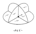
- the present invention comprises an assembly of identical radiation detectors, and, in particular, an assembly of four detectors, each with a baffle arrangement comprising three, at least substantially orthogonally arranged plane mirrors 11, and the assembly having a common receiving head.
- a baffle arrangement comprising three, at least substantially orthogonally arranged plane mirrors 11, and the assembly having a common receiving head.
- one constituent plane mirror 11 of each of the baffle arrangements has a common plane associated therewith, and, on the common plane there is a common point of intersection for three plane mirrors of each of the four detectors as for extensions of those mirrors.
- the defined field of view of the assembly is 2 ⁇ steradians. Only the receiving surface 10 of one of the constituent radiation detectors is shown in Figure 2.
- the constituent radiation detectors of the assembly can have any construction for a radiation detector, as described above.
- the assembly may have a common four core optical fibre, not shown in Figure 2.
- Each constituent core of the optical fibre is arranged with one end thereof individually to receive radiation incident upon the associated detector, and the core individually is to transmit radiation received by the core within the common receiving head, to one of four electro-optic devices provided within assembly.
- the assembly is arranged to indicate from which of the four defined fields of view of the four radiation detectors radiation is incident upon the common receiving head.
- a common electro-optic device is provided within the assembly.
- the common receiving head of the assembly of radiation detectors can be housed in a hemispherical, transparent, dome.
- the plane mirrors are kept clean, and free of rain.
Landscapes
- Physics & Mathematics (AREA)
- General Physics & Mathematics (AREA)
- Spectroscopy & Molecular Physics (AREA)
- Remote Sensing (AREA)
- Engineering & Computer Science (AREA)
- Radar, Positioning & Navigation (AREA)
- Electromagnetism (AREA)
- Measurement Of Radiation (AREA)
- Light Receiving Elements (AREA)
- Magnetic Resonance Imaging Apparatus (AREA)
- Apparatus For Radiation Diagnosis (AREA)
- Analysing Materials By The Use Of Radiation (AREA)
- Photometry And Measurement Of Optical Pulse Characteristics (AREA)
- Optical Couplings Of Light Guides (AREA)
Applications Claiming Priority (2)
| Application Number | Priority Date | Filing Date | Title |
|---|---|---|---|
| GB8925736A GB2238113B (en) | 1989-11-14 | 1989-11-14 | A radiation detector having a defined field of view |
| GB8925736 | 1989-11-14 |
Publications (3)
| Publication Number | Publication Date |
|---|---|
| EP0428345A2 true EP0428345A2 (fr) | 1991-05-22 |
| EP0428345A3 EP0428345A3 (en) | 1992-03-18 |
| EP0428345B1 EP0428345B1 (fr) | 1994-09-14 |
Family
ID=10666297
Family Applications (1)
| Application Number | Title | Priority Date | Filing Date |
|---|---|---|---|
| EP90312275A Expired - Lifetime EP0428345B1 (fr) | 1989-11-14 | 1990-11-09 | Tête de réception pour un détecteur de rayonnement possédant un champ de vue défini |
Country Status (7)
| Country | Link |
|---|---|
| US (1) | US5113069A (fr) |
| EP (1) | EP0428345B1 (fr) |
| AT (1) | ATE111595T1 (fr) |
| BR (1) | BR9005779A (fr) |
| DE (1) | DE69012513T2 (fr) |
| ES (1) | ES2058819T3 (fr) |
| GB (1) | GB2238113B (fr) |
Cited By (2)
| Publication number | Priority date | Publication date | Assignee | Title |
|---|---|---|---|---|
| EP0693175A4 (fr) * | 1993-04-07 | 1997-09-17 | Dennis J Hegyi | Capteur de commande combinee des phares et des conditions climatiques ambiantes |
| GB2347998A (en) * | 1999-03-16 | 2000-09-20 | Litron Optical Limited | Method and apparatus for measuring the intensity of a beam of light |
Families Citing this family (3)
| Publication number | Priority date | Publication date | Assignee | Title |
|---|---|---|---|---|
| US5288992A (en) * | 1992-12-15 | 1994-02-22 | Gte Laboratories Incorporated | Wide angle, narrow band optical filter |
| US6895557B1 (en) * | 1999-07-21 | 2005-05-17 | Ipix Corporation | Web-based media submission tool |
| US7414724B2 (en) * | 2006-11-17 | 2008-08-19 | Eppendorf Ag | Light diffuser used in a testing apparatus |
Family Cites Families (7)
| Publication number | Priority date | Publication date | Assignee | Title |
|---|---|---|---|---|
| US3448276A (en) * | 1965-02-09 | 1969-06-03 | Wolfgang Witte | Condenser-type optical system with conical light piping member for radiation detector |
| US3413468A (en) * | 1966-02-14 | 1968-11-26 | Barnes Eng Co | Means for improving the optical gain of an infrared detector |
| US4041321A (en) * | 1974-11-04 | 1977-08-09 | Robert Housu Linard | Measuring apparatus |
| CH596621A5 (fr) * | 1976-06-30 | 1978-03-15 | Cerberus Ag | |
| DE3642275A1 (de) * | 1986-12-11 | 1988-06-23 | Kernforschungsanlage Juelich | Einlasssystem fuer photodetektoren mit 180(grad) bildwinkel und damit versehene detektoren |
| DE3818815A1 (de) * | 1988-06-03 | 1989-12-14 | Zeiss Carl Fa | Remissionsmessgeraet |
| US4868383A (en) * | 1988-09-08 | 1989-09-19 | Eastman Kodak Company | Linear integrating cavity light source used for generating an intense beam of light |
-
1989
- 1989-11-14 GB GB8925736A patent/GB2238113B/en not_active Expired - Fee Related
-
1990
- 1990-11-09 EP EP90312275A patent/EP0428345B1/fr not_active Expired - Lifetime
- 1990-11-09 DE DE69012513T patent/DE69012513T2/de not_active Expired - Fee Related
- 1990-11-09 AT AT90312275T patent/ATE111595T1/de not_active IP Right Cessation
- 1990-11-09 ES ES90312275T patent/ES2058819T3/es not_active Expired - Lifetime
- 1990-11-14 US US07/612,388 patent/US5113069A/en not_active Expired - Lifetime
- 1990-11-14 BR BR909005779A patent/BR9005779A/pt active Search and Examination
Cited By (2)
| Publication number | Priority date | Publication date | Assignee | Title |
|---|---|---|---|---|
| EP0693175A4 (fr) * | 1993-04-07 | 1997-09-17 | Dennis J Hegyi | Capteur de commande combinee des phares et des conditions climatiques ambiantes |
| GB2347998A (en) * | 1999-03-16 | 2000-09-20 | Litron Optical Limited | Method and apparatus for measuring the intensity of a beam of light |
Also Published As
| Publication number | Publication date |
|---|---|
| DE69012513T2 (de) | 1995-01-12 |
| DE69012513D1 (de) | 1994-10-20 |
| ATE111595T1 (de) | 1994-09-15 |
| GB8925736D0 (en) | 1990-05-30 |
| GB2238113A (en) | 1991-05-22 |
| ES2058819T3 (es) | 1994-11-01 |
| BR9005779A (pt) | 1991-09-24 |
| GB2238113B (en) | 1993-07-28 |
| EP0428345A3 (en) | 1992-03-18 |
| EP0428345B1 (fr) | 1994-09-14 |
| US5113069A (en) | 1992-05-12 |
Similar Documents
| Publication | Publication Date | Title |
|---|---|---|
| US4914284A (en) | Optical wide angle sensor head | |
| CN101963676B (zh) | 用于过冷空中水滴的飞行中多视场探测器 | |
| US5291196A (en) | Collision-avoidance method for cooperating carriers and onboard optical assembly designed for its implementation | |
| US4931771A (en) | Optical fiber intrusion location sensor for perimeter protection of precincts | |
| CA1320369C (fr) | Systeme de detection | |
| NO321926B1 (no) | Fremgangsmate og anordning for detektering av atmosfaeriske vaerforhold | |
| US3998552A (en) | Instrument responsive to back-scattered or back-reflected radiation having passive system for range correction | |
| JPH0440682B2 (fr) | ||
| US4721852A (en) | Laser-warning device for military vehicles | |
| GB2075213A (en) | Absorption gas sensors | |
| CA2175681A1 (fr) | Element optique constituant d'un reseau d'elements optiques dans un agencement d'affichage | |
| US4770544A (en) | Temperature sensor | |
| RU2113717C1 (ru) | Лазерная система обнаружения оптоэлектронных объектов | |
| US4411521A (en) | Optoelectric detection device especially for laser radiation | |
| US20180038730A1 (en) | Optical detector and system therefor | |
| EP0050138B1 (fr) | Detecteur de radiation | |
| US4385833A (en) | Apparatus for reception and radiation of electromagnetic energy in predetermined fields of view | |
| EP0428345A2 (fr) | Tête de réception pour un détecteur de rayonnement possédant un champ de vue défini | |
| US4942623A (en) | Device and method for modal separation and combination in an optical fiber intrusion detection system | |
| GB1567320A (en) | Scanners | |
| US5281807A (en) | Optical sensor head with sloped, convergent optical systems and beam diaphragm | |
| US4222632A (en) | Light receiving and reflecting device | |
| JPH05340805A (ja) | 観察光学素子の広いフィールド | |
| EP0168679B1 (fr) | Système de mesure du rayonnement électromagnétique venant de l'espace semi-infini | |
| US4153368A (en) | Electro-optical detector protection device |
Legal Events
| Date | Code | Title | Description |
|---|---|---|---|
| PUAI | Public reference made under article 153(3) epc to a published international application that has entered the european phase |
Free format text: ORIGINAL CODE: 0009012 |
|
| AK | Designated contracting states |
Kind code of ref document: A2 Designated state(s): AT BE CH DE DK ES FR GR IT LI LU NL SE |
|
| PUAL | Search report despatched |
Free format text: ORIGINAL CODE: 0009013 |
|
| AK | Designated contracting states |
Kind code of ref document: A3 Designated state(s): AT BE CH DE DK ES FR GR IT LI LU NL SE |
|
| 17P | Request for examination filed |
Effective date: 19920526 |
|
| 17Q | First examination report despatched |
Effective date: 19930527 |
|
| RAP1 | Party data changed (applicant data changed or rights of an application transferred) |
Owner name: GEC-MARCONI AVIONICS (HOLDINGS) LIMITED |
|
| GRAA | (expected) grant |
Free format text: ORIGINAL CODE: 0009210 |
|
| AK | Designated contracting states |
Kind code of ref document: B1 Designated state(s): AT BE CH DE DK ES FR GR IT LI LU NL SE |
|
| PG25 | Lapsed in a contracting state [announced via postgrant information from national office to epo] |
Ref country code: LI Effective date: 19940914 Ref country code: GR Free format text: LAPSE BECAUSE OF FAILURE TO SUBMIT A TRANSLATION OF THE DESCRIPTION OR TO PAY THE FEE WITHIN THE PRESCRIBED TIME-LIMIT Effective date: 19940914 Ref country code: DK Effective date: 19940914 Ref country code: CH Effective date: 19940914 Ref country code: AT Effective date: 19940914 |
|
| REF | Corresponds to: |
Ref document number: 111595 Country of ref document: AT Date of ref document: 19940915 Kind code of ref document: T |
|
| ITF | It: translation for a ep patent filed | ||
| REF | Corresponds to: |
Ref document number: 69012513 Country of ref document: DE Date of ref document: 19941020 |
|
| REG | Reference to a national code |
Ref country code: ES Ref legal event code: FG2A Ref document number: 2058819 Country of ref document: ES Kind code of ref document: T3 |
|
| PG25 | Lapsed in a contracting state [announced via postgrant information from national office to epo] |
Ref country code: LU Free format text: LAPSE BECAUSE OF NON-PAYMENT OF DUE FEES Effective date: 19941130 |
|
| ET | Fr: translation filed | ||
| REG | Reference to a national code |
Ref country code: CH Ref legal event code: PL |
|
| EAL | Se: european patent in force in sweden |
Ref document number: 90312275.2 |
|
| PLBE | No opposition filed within time limit |
Free format text: ORIGINAL CODE: 0009261 |
|
| STAA | Information on the status of an ep patent application or granted ep patent |
Free format text: STATUS: NO OPPOSITION FILED WITHIN TIME LIMIT |
|
| 26N | No opposition filed | ||
| PGFP | Annual fee paid to national office [announced via postgrant information from national office to epo] |
Ref country code: SE Payment date: 19951003 Year of fee payment: 6 |
|
| PGFP | Annual fee paid to national office [announced via postgrant information from national office to epo] |
Ref country code: ES Payment date: 19951024 Year of fee payment: 6 |
|
| PGFP | Annual fee paid to national office [announced via postgrant information from national office to epo] |
Ref country code: NL Payment date: 19951130 Year of fee payment: 6 |
|
| PGFP | Annual fee paid to national office [announced via postgrant information from national office to epo] |
Ref country code: DE Payment date: 19951228 Year of fee payment: 6 |
|
| PGFP | Annual fee paid to national office [announced via postgrant information from national office to epo] |
Ref country code: BE Payment date: 19960919 Year of fee payment: 7 |
|
| PG25 | Lapsed in a contracting state [announced via postgrant information from national office to epo] |
Ref country code: SE Effective date: 19961110 |
|
| PG25 | Lapsed in a contracting state [announced via postgrant information from national office to epo] |
Ref country code: ES Free format text: LAPSE BECAUSE OF EXPIRATION OF PROTECTION Effective date: 19961111 |
|
| PG25 | Lapsed in a contracting state [announced via postgrant information from national office to epo] |
Ref country code: NL Effective date: 19970601 |
|
| NLV4 | Nl: lapsed or anulled due to non-payment of the annual fee |
Effective date: 19970601 |
|
| PG25 | Lapsed in a contracting state [announced via postgrant information from national office to epo] |
Ref country code: DE Effective date: 19970801 |
|
| EUG | Se: european patent has lapsed |
Ref document number: 90312275.2 |
|
| PG25 | Lapsed in a contracting state [announced via postgrant information from national office to epo] |
Ref country code: BE Free format text: LAPSE BECAUSE OF NON-PAYMENT OF DUE FEES Effective date: 19971130 |
|
| BERE | Be: lapsed |
Owner name: GEC-MARCONI AVIONICS (HOLDINGS) LTD Effective date: 19971130 |
|
| REG | Reference to a national code |
Ref country code: ES Ref legal event code: FD2A Effective date: 20010301 |
|
| REG | Reference to a national code |
Ref country code: FR Ref legal event code: CD Ref country code: FR Ref legal event code: CA |
|
| PGFP | Annual fee paid to national office [announced via postgrant information from national office to epo] |
Ref country code: FR Payment date: 20041010 Year of fee payment: 15 |
|
| PG25 | Lapsed in a contracting state [announced via postgrant information from national office to epo] |
Ref country code: IT Free format text: LAPSE BECAUSE OF NON-PAYMENT OF DUE FEES Effective date: 20051109 |
|
| PG25 | Lapsed in a contracting state [announced via postgrant information from national office to epo] |
Ref country code: FR Free format text: LAPSE BECAUSE OF NON-PAYMENT OF DUE FEES Effective date: 20060731 |
|
| REG | Reference to a national code |
Ref country code: FR Ref legal event code: ST Effective date: 20060731 |