EP0428422A2 - Verfahren und Vorrichtung für Messungen in Zusammenhang mit einer Fluidströmung in einem Bohrloch - Google Patents
Verfahren und Vorrichtung für Messungen in Zusammenhang mit einer Fluidströmung in einem Bohrloch Download PDFInfo
- Publication number
- EP0428422A2 EP0428422A2 EP90402911A EP90402911A EP0428422A2 EP 0428422 A2 EP0428422 A2 EP 0428422A2 EP 90402911 A EP90402911 A EP 90402911A EP 90402911 A EP90402911 A EP 90402911A EP 0428422 A2 EP0428422 A2 EP 0428422A2
- Authority
- EP
- European Patent Office
- Prior art keywords
- fluid
- packer
- fluid flow
- measuring pipe
- measuring
- Prior art date
- Legal status (The legal status is an assumption and is not a legal conclusion. Google has not performed a legal analysis and makes no representation as to the accuracy of the status listed.)
- Granted
Links
Images
Classifications
-
- E—FIXED CONSTRUCTIONS
- E21—EARTH OR ROCK DRILLING; MINING
- E21B—EARTH OR ROCK DRILLING; OBTAINING OIL, GAS, WATER, SOLUBLE OR MELTABLE MATERIALS OR A SLURRY OF MINERALS FROM WELLS
- E21B33/00—Sealing or packing boreholes or wells
- E21B33/10—Sealing or packing boreholes or wells in the borehole
- E21B33/12—Packers; Plugs
- E21B33/126—Packers; Plugs with fluid-pressure-operated elastic cup or skirt
-
- E—FIXED CONSTRUCTIONS
- E21—EARTH OR ROCK DRILLING; MINING
- E21B—EARTH OR ROCK DRILLING; OBTAINING OIL, GAS, WATER, SOLUBLE OR MELTABLE MATERIALS OR A SLURRY OF MINERALS FROM WELLS
- E21B33/00—Sealing or packing boreholes or wells
- E21B33/10—Sealing or packing boreholes or wells in the borehole
- E21B33/12—Packers; Plugs
- E21B33/127—Packers; Plugs with inflatable sleeve
-
- E—FIXED CONSTRUCTIONS
- E21—EARTH OR ROCK DRILLING; MINING
- E21B—EARTH OR ROCK DRILLING; OBTAINING OIL, GAS, WATER, SOLUBLE OR MELTABLE MATERIALS OR A SLURRY OF MINERALS FROM WELLS
- E21B47/00—Survey of boreholes or wells
- E21B47/10—Locating fluid leaks, intrusions or movements
-
- G—PHYSICS
- G01—MEASURING; TESTING
- G01F—MEASURING VOLUME, VOLUME FLOW, MASS FLOW OR LIQUID LEVEL; METERING BY VOLUME
- G01F1/00—Measuring the volume flow or mass flow of fluid or fluent solid material wherein the fluid passes through a meter in a continuous flow
- G01F1/05—Measuring the volume flow or mass flow of fluid or fluent solid material wherein the fluid passes through a meter in a continuous flow by using mechanical effects
- G01F1/10—Measuring the volume flow or mass flow of fluid or fluent solid material wherein the fluid passes through a meter in a continuous flow by using mechanical effects using rotating vanes with axial admission
-
- G—PHYSICS
- G01—MEASURING; TESTING
- G01F—MEASURING VOLUME, VOLUME FLOW, MASS FLOW OR LIQUID LEVEL; METERING BY VOLUME
- G01F15/00—Details of, or accessories for, apparatus of groups G01F1/00 - G01F13/00 insofar as such details or appliances are not adapted to particular types of such apparatus
Definitions
- the present invention relates to a method and an apparatus for use in a borehole having fluid therein, and designed to carry out measurements related to said fluid, such as the flow rate and velocity. More particularly, the invention pertains to the kind of logging tool called "packer flowmeter", wherein the fluid is diverted into a measuring pipe including a flowmeter device which is of reduced cross section with respect to the casing.
- a well which has been determined to be promising for oil production is provided with a metallic casing, and cement is injected between the earth formation and the casing. Perforations are then made through the casing/cement and in the oil productive formation, so as to allow oil to flow up to the surface through a tubing beforehand arranged in the well coaxially to the casing.
- the amount of oil produced is the amount of oil produced.
- the invention may also be used, besides the production wells hereabove referred to, in the so-called "injection wells" in which a high pressure fluid is injected in a first well so as to make the oil move in earth formation towards a neighboring second well which will become the oil producing well.
- packers are made, either of an inflated cloth bag disposed inside a cage made of longitudinal metal blades, or of a metal basket. Examples of such known packers are described e.g. in U.S. Patents 2,649,710; 2,706,406,; 3,176,511; 4,552,076; 4,566,317; or 4,800,752.
- the additional inflatable tube requires a pump, which increases the complexity of the tool.
- the water phase at the exit of the measuring pipe, because of gravity, separates from the oil phase and falls down in the annulus situated above the packer. Accordingly, the upper side (or downstream side) of the packer is submitted to a higher pressure than the bottom side (or upstream side) of the same. This is detrimental since it may cause the packer to collapse down, at least locally, and thus create a substantial leak in the sealing.
- the design of the terminal part of the packer in contact with the casing is critical. Since the packer is attached to the support metal blades by this very terminal part, it has to be strong. However, the sealing requires the terminal part to be as soft as possible in order to match the form of the casing. These two opposite requirements lead to a non satisfactory compromise.
- a method for carrying out measurements in a borehole related to the fluid therein by a logging tool including a measuring pipe provided with measuring means, and a packer means designed to derive the whole fluid flow into said measuring pipe, comprising the step of increasing, through the fluid flow action, the pressure of the fluid located substantially upstream of the packer.
- the method includes providing obstacle means in the path of the flowing fluid, at, or downstream of, the top of the packer.
- the invention also contemplates a logging tool for carrying out measurements in a well related to the fluid therein, including a measuring pipe provided with measuring means, a packer means designed to derive the whole fluid flow into said measuring pipe, and means for increasing, through the fluid flow action, the pressure of the fluid located substantially upstream of the packer.
- said means for increasing pressure includes obstacle means disposed in the fluid flow path, at, or downstream of, the end of said packer facing the measuring pipe.
- the obstacle means comprises a moving element responsive to flowing fluid pressure on one side and to biasing means on the other side.
- said biasing means comprises a compression spring.
- the moving element is a valve including a valve seat and a valve piston slidably mounted along a fixed longitudinal rod.
- valve piston is hollowed in its portion facing said valve seat.
- a logging tool for carrying out measurements in a well related to the fluid therein, comprising a housing including a measuring pipe provided with measuring means, and packer means designed to derive the whole fluid flow into said measuring pipe, wherein said packer means includes, in its bottom end designed to seal with the casing wall, a annulus sealing means able to be inflated under the fluid action.
- the packer means includes a cone-shaped bag
- the inflatable annulus sealing means comprises two circumferential parts, facing one another, and fixed along their upper and lower perimeters so as to define a ring-shaped chamber in communication with the fluid flow and adapted to expand radially upon the application of fluid pressure while being substantially longitudinally non-extensible.
- the packer bag is made of a flexible but substantially longitudinally non-extensible material, such as cloth, and the annulus sealing means comprises a circumferential piece fixed on the terminal part of the bag by its upper and lower perimeters, and adapted to expand radially upon the application of fluid pressure.
- said circumferential piece is made of a flexible but substantially longitudinally non-extensible material, and is loosely fixed on the bag for allowing radial expansion.
- said ring-shaped chamber communicates with the fluid flow inside the cone-shaped packer by apertures provided in the packer.
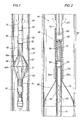
- a well logging tool 60 in accordance with the invention is shown disposed within a borehole 61 which has a conventional well casing 62 disposed on the interior surface of the borehole.
- Flowing fluids, such as hydrocarbons, are shown by arrows 63in and 63out and pass through the well logging tool 60.
- the logging tool 60 comprises: a housing 64, a measuring pipe 65 including means for measuring characteristics of the fluid flow, which measuring pipe 65 is located inside the housing 64, means for sealing the casing and for directing the flowing fluid into the housing 64 and more specifically inside the measuring pipe 65.
- the means for sealing and directing fluid comprises a packer type device in the form of a frusto-conical shaped bag 66 provided with a narrow end 66a attached to the housing and a wide end 66b coming into sealing engagement with the borehole wall.
- the packer bag 66 is disposed in a cage formed by a set of longitudinal blades 67 which are radially foldable.
- the blades 67 are fixed at both ends on the housing 64.
- the bottom ends 70 of the metal blades 67 are fixed on a first ring 55 which is slidably mounted on a central pipe 71.
- the top ends 56 of the blades 67 are fixed on a second ring 50 secured to said housing 64.
- the longitudinal displacement of the ring allows the set of packer bag/blades to be either opened out (as shown on FIG. 1) or folded down along the tool (e.g. when the tool is displaced from one measuring station in the borehole to another). Downstream of the measuring pipe 65, the housing 64 comprises apertures 72 for the flow to exit (see arrows 63out) from the measuring pipe 65 into the casing 62.
- the means for measuring are known per se and may comprise a flowmeter, such as a spinner, whereby the characteristic to be measured is the flow rate of the fluid.
- the casing 62 has a plurality of perforations (not shown) disposed about its circumference and along its length, through which flowing formation fluids pass from the borehole 61 into casing 62.
- downstream and upstream refer to the fluid flow which is ascendant in the substantially vertical borehole.
- bottom and “lower” on the one part, and “upper” and “top” on the other part are indicative of a respective location referred to with respect to the substantially vertical direction in the borehole.
- longitudinally refers to the axial direction of the borehole, and “radially” refers to the direction transverse to the borehole axis.
- FIG. 2 is an enlarged partial cross-sectional view of the tool of FIG. 1.
- the central pipe 71 comprises, in the section located inside the cloth bag packer 66, holes 73 allowing the fluid (see arrows 63in) to flow inside central pipe 71 which is aligned and in fluid communication with the measuring pipe 65.
- a measuring device such as a spinner 68, which is well known in the art, is disposed inside said measuring pipe 65.
- Holes 72 are provided downstream of the spinner 68 in the housing 64 to allow the fluid to exit from the measuring pipe 65, as indicated by the arrows 63out.
- the narrow end 66a of the packer 66 is substantially circumferential and is secured on the upper end 71a of the central pipe 71.
- the end 64a of the housing 64 is in turn engaged with said upper end 71a of the central pipe 71.
- an obstacle in the form of a valve designed to increase, in a controlled way, the pressure inside the packer bag 66 with respect to the pressure outside the packer, i.e. the pressure of the fluid located above the packer.
- the valve is disposed at the level of the top of the packer bag 66, and downstream of the measuring pipe 65.
- the valve includes a valve piston 80, substantially circumferential and slidably mounted on a longitudinal rod 81. Said rod 81 is fixed and centered inside the measuring pipe 65 by a hub 82. Said hub 82 is fixedly attached to the wall of the measuring pipe 65 and is designed to allow the fluid to flow therethrough.
- the valve piston 80 has such a shape and dimensions that it is able to cooperate with a valve seat 83 formed at the upper end 71a of the central pipe 71.
- the piston 80 when bearing against the valve seat 83 closes the fluid path.
- the valve seat 83 may be for instance formed by the edge of the central pipe end 71a. Said edge of the piston may be bevelled towards the inside.
- the piston 80 is submitted on its upstream end to the fluid pressure in central pipe 71, and on its downstream end to a biasing force from a compression spring 84, coaxially mounted with respect to the rod 81.
- the spring 84 bears by its upper end (opposite to the piston) against the hub 82.
- the internal diameter of the measuring pipe 65 may be of 1.3 inch (about 3.5 centimeters) and the diameter of the valve piston 80 may be around 1.1 inch (2.8 centimeters).
- the piston 80 Upon the application of fluid pressure in central pipe 71, the piston 80 is displaced with respect to the valve seat 83, thus allowing the fluid to pass from the central pipe 71 towards the measuring pipe 65.
- the presence of the valve in the fluid path results in an increase of the pressure inside the packer 66.
- the pressure increase (due to the valve only) is in the range of a fraction of psi to a few psi, e.g. from 0.2 to 2 psi (approximately 0.014 to 0.14 Kg/cm2).
- the pressure increase depends upon the flow rate.
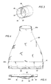
- FIG. 3 is a perspective illustration of the valve piston 80 which is made of a circumferential element comprising a centered hole 89 cooperating with the rod 81.
- the piston 80 has a hollowed part 85 in the upstream portion of the same.
- the upstream part of the piston facing the flow has a concave shape.
- the hollowed part 85 defines a circumferential wall 86 with an edge 87 which is designed to cooperate with the valve seat 83.
- This particular design of the piston area facing the flow is intended to reduce as much as possible the area of the piston in contact with the flow (in that case the edge 87) in order to cancel, or at least alleviate, the Venturi effect which would have resulted in a pressure force applied on the valve piston in a direction opposite to the flow, i.e. towards the valve seat, and thus preventing the flow.
- FIG. 4 and FIG. 5 show another feature of the invention, providing an improved seal between the packer 66 and the borehole wall or casing.
- the packer bag 66 has to be substantially non extensible in the longitudinal direction so as to resist the pressure on both sides thereupon.
- the bag is made of a synthetic cloth such as Nylon or polyester.
- the very bottom end of the packer bag i.e. the wide end 66b) comprises holes 90 designed to cooperate with attaching means (non shown) provided on the metal blades 67. Referring to FIG.
- an inflatable annulus sealing means which might be inflated by the fluid and under the sole fluid action.
- said annulus sealing is made by securing on the packer bag 66 a circumferential cloth piece 91, preferably by sewing the respective upper and lower perimeters 94, 95 of said piece 91 to said packer.
- said piece 91 is disposed on the outer side of the packer wall, i.e. on the side facing the borehole wall.
- the wall of the bag 66 and said piece 91 define a tubular chamber 92 which communicates with the fluid inside the packer bag 66 through apertures 93 provided on the portion of the packer bag wall disposed in regard to the piece 91.
- the circumferential piece 91 is designed to expand radially.
- the piece 91 is made of a cloth similar to the cloth of the packer bag 66, and is fixed on the same in a slightly folded way.
- the circumferential piece 91 has a diameter which is greater than the diameter of the bottom (wide) end of the packer.
- the fluid fills the ring-shaped chamber 92 through the apertures 93 and said chamber can expand.
- This feature allows the packer bag 66 to meet two opposite conditions, i.e. being resistant in the longitudinal direction and being relatively soft (at least in the terminal part designated to contact the casing wall) for fitting as much as possible the form of the casing wall.
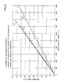
- FIG. 6 shows plots of the spinner speed (in rotation per second) versus fluid flow rate "Q" (in barrel per day; 100 barrels are sensibly equivalent to 15.9 m3). All the three plots shown are constituted by straight lines corresponding each to the same spinner flowmeter 68 submitted to different conditions. Each line is e.g. a least squares line related to a set of points resulting from a given experimentation. Line 1 is the reference response of the spinner; in other words, line 1 represents the theoretical relationship between the spinner speed and flow rate, should the spinner be associated with a theoretically perfect packer providing a perfect seal (i.e. without any fluid leak) between the packer and the casing.
- Line 2 corresponds to the response of the spinner 68 associated with a prior art type packer, such as the one described in U.S. Patent 4,800,752.
- Line 3 corresponds to the response of the spinner associated with the packer of the present invention.
- FIG. 6 shows conspicuously that the packer according to the present invention (i) provides a far better seal than the prior art packers, and (ii) is very close to the reference or "no-leak" response.
Landscapes
- Physics & Mathematics (AREA)
- Life Sciences & Earth Sciences (AREA)
- Engineering & Computer Science (AREA)
- Geology (AREA)
- Mining & Mineral Resources (AREA)
- Fluid Mechanics (AREA)
- Environmental & Geological Engineering (AREA)
- General Life Sciences & Earth Sciences (AREA)
- Geochemistry & Mineralogy (AREA)
- General Physics & Mathematics (AREA)
- Geophysics (AREA)
- Geophysics And Detection Of Objects (AREA)
Applications Claiming Priority (2)
| Application Number | Priority Date | Filing Date | Title |
|---|---|---|---|
| US07/422,822 US5052220A (en) | 1989-10-17 | 1989-10-17 | Apparatus for measurements related to fluid flow in a borehole |
| US422822 | 1989-10-17 |
Publications (3)
| Publication Number | Publication Date |
|---|---|
| EP0428422A2 true EP0428422A2 (de) | 1991-05-22 |
| EP0428422A3 EP0428422A3 (en) | 1993-03-03 |
| EP0428422B1 EP0428422B1 (de) | 1998-01-07 |
Family
ID=23676549
Family Applications (1)
| Application Number | Title | Priority Date | Filing Date |
|---|---|---|---|
| EP90402911A Expired - Lifetime EP0428422B1 (de) | 1989-10-17 | 1990-10-17 | Verfahren und Vorrichtung für Messungen in Zusammenhang mit einer Fluidströmung in einem Bohrloch |
Country Status (5)
| Country | Link |
|---|---|
| US (1) | US5052220A (de) |
| EP (1) | EP0428422B1 (de) |
| AU (1) | AU636671B2 (de) |
| DE (1) | DE69031900D1 (de) |
| NO (1) | NO302051B1 (de) |
Cited By (3)
| Publication number | Priority date | Publication date | Assignee | Title |
|---|---|---|---|---|
| GB2406593A (en) * | 2003-10-03 | 2005-04-06 | Schlumberger Holdings | Well packer having an energized sealing element and associated method |
| FR2938602A1 (fr) * | 2008-11-19 | 2010-05-21 | Sondex Wireline Ltd | Dispositif de modulateur en puits |
| WO2022220693A1 (en) * | 2021-04-12 | 2022-10-20 | Archer Oiltools As | Improved seal assembly and washing tool |
Families Citing this family (25)
| Publication number | Priority date | Publication date | Assignee | Title |
|---|---|---|---|---|
| US5586027A (en) * | 1989-06-12 | 1996-12-17 | Western Atlas International, Inc. | Method and apparatus for determining flow rates in multi-phase fluid flow mixtures |
| US7347274B2 (en) | 2004-01-27 | 2008-03-25 | Schlumberger Technology Corporation | Annular barrier tool |
| FI120324B (fi) * | 2006-09-12 | 2009-09-15 | Posiva Oy | Virtausmittari |
| US8316704B2 (en) * | 2008-10-14 | 2012-11-27 | Schlumberger Technology Corporation | Downhole annular measurement system and method |
| US9109427B2 (en) * | 2010-07-01 | 2015-08-18 | Basimah Khulusi | Apparatus and method for plugging blowouts |
| US9121966B2 (en) * | 2011-11-28 | 2015-09-01 | Baker Hughes Incorporated | Media displacement device and method of improving transfer of electromagnetic energy between a tool and an earth formation |
| CN103388470B (zh) * | 2012-05-08 | 2017-06-13 | 中国石油化工股份有限公司 | 凸轮集流式稠油产液剖面直读测试仪 |
| US9745820B2 (en) | 2015-04-28 | 2017-08-29 | Thru Tubing Solutions, Inc. | Plugging device deployment in subterranean wells |
| US10774612B2 (en) | 2015-04-28 | 2020-09-15 | Thru Tubing Solutions, Inc. | Flow control in subterranean wells |
| US10233719B2 (en) | 2015-04-28 | 2019-03-19 | Thru Tubing Solutions, Inc. | Flow control in subterranean wells |
| US10851615B2 (en) | 2015-04-28 | 2020-12-01 | Thru Tubing Solutions, Inc. | Flow control in subterranean wells |
| US10655427B2 (en) | 2015-04-28 | 2020-05-19 | Thru Tubing Solutions, Inc. | Flow control in subterranean wells |
| US9567825B2 (en) | 2015-04-28 | 2017-02-14 | Thru Tubing Solutions, Inc. | Flow control in subterranean wells |
| US10641069B2 (en) | 2015-04-28 | 2020-05-05 | Thru Tubing Solutions, Inc. | Flow control in subterranean wells |
| US10513653B2 (en) | 2015-04-28 | 2019-12-24 | Thru Tubing Solutions, Inc. | Flow control in subterranean wells |
| US11851611B2 (en) | 2015-04-28 | 2023-12-26 | Thru Tubing Solutions, Inc. | Flow control in subterranean wells |
| US9567824B2 (en) | 2015-04-28 | 2017-02-14 | Thru Tubing Solutions, Inc. | Fibrous barriers and deployment in subterranean wells |
| US9816341B2 (en) | 2015-04-28 | 2017-11-14 | Thru Tubing Solutions, Inc. | Plugging devices and deployment in subterranean wells |
| US9567826B2 (en) | 2015-04-28 | 2017-02-14 | Thru Tubing Solutions, Inc. | Flow control in subterranean wells |
| WO2018007026A1 (en) * | 2016-07-02 | 2018-01-11 | Openfield | A production logging tool and downhole fluid analysis probes deploying method, in particular for deviated and horizontal hydrocarbon well. |
| US11022248B2 (en) | 2017-04-25 | 2021-06-01 | Thru Tubing Solutions, Inc. | Plugging undesired openings in fluid vessels |
| US11293578B2 (en) | 2017-04-25 | 2022-04-05 | Thru Tubing Solutions, Inc. | Plugging undesired openings in fluid conduits |
| CN109386249B (zh) * | 2018-12-12 | 2023-05-16 | 四川省科学城久利电子有限责任公司 | 一种用于油田油管的全集流器 |
| CN109899014B (zh) * | 2019-01-31 | 2021-05-11 | 张化庆 | 一种注水井内的投捞装置、控制方法和控制装置 |
| GB2597330B (en) | 2020-07-20 | 2022-07-13 | Reeves Wireline Tech Ltd | Apparatuses and methods for signalling between downhole and uphole locations |
Family Cites Families (13)
| Publication number | Priority date | Publication date | Assignee | Title |
|---|---|---|---|---|
| US2451762A (en) * | 1945-07-04 | 1948-10-19 | Geophysical Res Corp | Packing ring |
| US2681706A (en) * | 1949-12-30 | 1954-06-22 | Stanolind Oil & Gas Co | Inflatable well packer |
| US2932740A (en) * | 1956-04-18 | 1960-04-12 | Texaco Inc | Bore hole fluid mixing apparatus |
| US3066739A (en) * | 1958-12-10 | 1962-12-04 | Schlumberger Well Surv Corp | Borehole apparatus |
| US3176511A (en) * | 1962-09-25 | 1965-04-06 | Texaco Inc | Productivtity well logging |
| US3942374A (en) * | 1968-05-23 | 1976-03-09 | N L Industries, Inc. | Apparatus for the determination of the quantity of oil |
| US4441361A (en) * | 1981-10-02 | 1984-04-10 | Dresser Industries, Inc. | Method and apparatus for measurement of fluid density and flow rates in multi-phase flow regimes |
| US4452076A (en) * | 1982-06-21 | 1984-06-05 | Schlumberger Technology Corporation | Well logging tool |
| US4460041A (en) * | 1982-09-13 | 1984-07-17 | Baker Oil Tools, Inc. | Subterranean well tool with pressure equalizing release |
| US4460040A (en) * | 1982-11-24 | 1984-07-17 | Baker Oil Tools, Inc. | Equalizing annulus valve |
| US4566317A (en) * | 1984-01-30 | 1986-01-28 | Schlumberger Technology Corporation | Borehole flow meter |
| US4770212A (en) * | 1985-12-13 | 1988-09-13 | Halliburton Company | Pressure compensated flow rate controllers |
| US4800752A (en) * | 1987-07-01 | 1989-01-31 | Schlumberger Technology Corporation | Flow restricting logging tool and method |
-
1989
- 1989-10-17 US US07/422,822 patent/US5052220A/en not_active Expired - Lifetime
-
1990
- 1990-10-16 AU AU64660/90A patent/AU636671B2/en not_active Ceased
- 1990-10-16 NO NO904465A patent/NO302051B1/no not_active IP Right Cessation
- 1990-10-17 EP EP90402911A patent/EP0428422B1/de not_active Expired - Lifetime
- 1990-10-17 DE DE69031900T patent/DE69031900D1/de not_active Expired - Lifetime
Cited By (8)
| Publication number | Priority date | Publication date | Assignee | Title |
|---|---|---|---|---|
| GB2406593A (en) * | 2003-10-03 | 2005-04-06 | Schlumberger Holdings | Well packer having an energized sealing element and associated method |
| GB2417271A (en) * | 2003-10-03 | 2006-02-22 | Schlumberger Holdings | Well packer having an energized sealing element and associated method |
| GB2406593B (en) * | 2003-10-03 | 2006-06-28 | Schlumberger Holdings | Well packer having an energized sealing element and associated method |
| GB2417271B (en) * | 2003-10-03 | 2006-07-12 | Schlumberger Holdings | Well packer having an energized sealing element and associated method |
| US7234533B2 (en) | 2003-10-03 | 2007-06-26 | Schlumberger Technology Corporation | Well packer having an energized sealing element and associated method |
| FR2938602A1 (fr) * | 2008-11-19 | 2010-05-21 | Sondex Wireline Ltd | Dispositif de modulateur en puits |
| US8453744B2 (en) | 2008-11-19 | 2013-06-04 | Sondex Wireline Limited | Downhole modulator apparatus |
| WO2022220693A1 (en) * | 2021-04-12 | 2022-10-20 | Archer Oiltools As | Improved seal assembly and washing tool |
Also Published As
| Publication number | Publication date |
|---|---|
| DE69031900D1 (de) | 1998-02-12 |
| US5052220A (en) | 1991-10-01 |
| NO904465L (no) | 1991-04-18 |
| AU6466090A (en) | 1991-04-26 |
| AU636671B2 (en) | 1993-05-06 |
| EP0428422B1 (de) | 1998-01-07 |
| NO302051B1 (no) | 1998-01-12 |
| EP0428422A3 (en) | 1993-03-03 |
| NO904465D0 (no) | 1990-10-16 |
Similar Documents
| Publication | Publication Date | Title |
|---|---|---|
| US5052220A (en) | Apparatus for measurements related to fluid flow in a borehole | |
| US3196949A (en) | Apparatus for completing wells | |
| EP0297962B1 (de) | Messgerät und Verfahren zum Beschränken des Durchflusses in einem Bohrloch | |
| CA1153691A (en) | Isolation gravel packer | |
| US5107927A (en) | Orienting tool for slant/horizontal completions | |
| CA1159360A (en) | Multiple stage cementer and casing inflation packer | |
| US6554580B1 (en) | Plunger for well casings and other tubulars | |
| US4889473A (en) | Production plunger | |
| US5226485A (en) | Pass-through zone isolation packer and process for isolating zones in a multiple-zone well | |
| US5271461A (en) | Coiled tubing deployed inflatable stimulation tool | |
| USRE32345E (en) | Packer valve arrangement | |
| US5832998A (en) | Coiled tubing deployed inflatable stimulation tool | |
| JPS5912835B2 (ja) | サンプル採取・測定装置 | |
| US4802359A (en) | Tool for measuring pressure in an oil well | |
| CA1193542A (en) | Packer flowmeter with bypass | |
| US3934467A (en) | Spinner flowmeter with isolated bearings | |
| CA2068913C (en) | Down-hole concentric chamber gas separator | |
| AU597868B2 (en) | Drill stem test method and apparatus | |
| US5062481A (en) | Control of `U` tubing in the flow of cement in oil well casings | |
| RU2121564C1 (ru) | Устройство для свабирования скважин | |
| US4577695A (en) | Sequential inflatable packer | |
| US2674126A (en) | Fluid-operated free pump with formation pressure tester | |
| US3937280A (en) | Artificial lift well apparatus | |
| US3386390A (en) | Gas anchor | |
| US2876703A (en) | Multiple gas lift production |
Legal Events
| Date | Code | Title | Description |
|---|---|---|---|
| PUAI | Public reference made under article 153(3) epc to a published international application that has entered the european phase |
Free format text: ORIGINAL CODE: 0009012 |
|
| AK | Designated contracting states |
Kind code of ref document: A2 Designated state(s): DE FR GB NL |
|
| PUAL | Search report despatched |
Free format text: ORIGINAL CODE: 0009013 |
|
| RHK1 | Main classification (correction) |
Ipc: E21B 47/00 |
|
| AK | Designated contracting states |
Kind code of ref document: A3 Designated state(s): DE FR GB NL |
|
| 17P | Request for examination filed |
Effective date: 19930828 |
|
| R17P | Request for examination filed (corrected) |
Effective date: 19930828 |
|
| 17Q | First examination report despatched |
Effective date: 19950517 |
|
| GRAG | Despatch of communication of intention to grant |
Free format text: ORIGINAL CODE: EPIDOS AGRA |
|
| GRAH | Despatch of communication of intention to grant a patent |
Free format text: ORIGINAL CODE: EPIDOS IGRA |
|
| GRAH | Despatch of communication of intention to grant a patent |
Free format text: ORIGINAL CODE: EPIDOS IGRA |
|
| GRAA | (expected) grant |
Free format text: ORIGINAL CODE: 0009210 |
|
| AK | Designated contracting states |
Kind code of ref document: B1 Designated state(s): DE FR GB NL |
|
| PG25 | Lapsed in a contracting state [announced via postgrant information from national office to epo] |
Ref country code: FR Free format text: LAPSE BECAUSE OF FAILURE TO SUBMIT A TRANSLATION OF THE DESCRIPTION OR TO PAY THE FEE WITHIN THE PRESCRIBED TIME-LIMIT Effective date: 19980107 Ref country code: NL Free format text: LAPSE BECAUSE OF FAILURE TO SUBMIT A TRANSLATION OF THE DESCRIPTION OR TO PAY THE FEE WITHIN THE PRESCRIBED TIME-LIMIT Effective date: 19980107 |
|
| REF | Corresponds to: |
Ref document number: 69031900 Country of ref document: DE Date of ref document: 19980212 |
|
| PG25 | Lapsed in a contracting state [announced via postgrant information from national office to epo] |
Ref country code: DE Free format text: LAPSE BECAUSE OF FAILURE TO SUBMIT A TRANSLATION OF THE DESCRIPTION OR TO PAY THE FEE WITHIN THE PRESCRIBED TIME-LIMIT Effective date: 19980408 |
|
| NLV1 | Nl: lapsed or annulled due to failure to fulfill the requirements of art. 29p and 29m of the patents act | ||
| EN | Fr: translation not filed | ||
| PLBE | No opposition filed within time limit |
Free format text: ORIGINAL CODE: 0009261 |
|
| STAA | Information on the status of an ep patent application or granted ep patent |
Free format text: STATUS: NO OPPOSITION FILED WITHIN TIME LIMIT |
|
| 26N | No opposition filed | ||
| REG | Reference to a national code |
Ref country code: GB Ref legal event code: IF02 |
|
| PGFP | Annual fee paid to national office [announced via postgrant information from national office to epo] |
Ref country code: GB Payment date: 20071017 Year of fee payment: 18 |
|
| GBPC | Gb: european patent ceased through non-payment of renewal fee |
Effective date: 20081017 |
|
| PG25 | Lapsed in a contracting state [announced via postgrant information from national office to epo] |
Ref country code: GB Free format text: LAPSE BECAUSE OF NON-PAYMENT OF DUE FEES Effective date: 20081017 |