EP0428471A2 - Rouleau de guidage aspirant - Google Patents
Rouleau de guidage aspirant Download PDFInfo
- Publication number
- EP0428471A2 EP0428471A2 EP90630178A EP90630178A EP0428471A2 EP 0428471 A2 EP0428471 A2 EP 0428471A2 EP 90630178 A EP90630178 A EP 90630178A EP 90630178 A EP90630178 A EP 90630178A EP 0428471 A2 EP0428471 A2 EP 0428471A2
- Authority
- EP
- European Patent Office
- Prior art keywords
- shell
- housing
- web
- relative
- shaft
- Prior art date
- Legal status (The legal status is an assumption and is not a legal conclusion. Google has not performed a legal analysis and makes no representation as to the accuracy of the status listed.)
- Granted
Links
- 238000007789 sealing Methods 0.000 claims abstract description 25
- 238000011144 upstream manufacturing Methods 0.000 claims abstract description 15
- 230000002401 inhibitory effect Effects 0.000 claims description 10
- 241000239290 Araneae Species 0.000 claims description 9
- 238000000034 method Methods 0.000 claims description 8
- 240000000254 Agrostemma githago Species 0.000 description 2
- 235000009899 Agrostemma githago Nutrition 0.000 description 2
- 238000012986 modification Methods 0.000 description 2
- 230000004048 modification Effects 0.000 description 2
- XLYOFNOQVPJJNP-UHFFFAOYSA-N water Substances O XLYOFNOQVPJJNP-UHFFFAOYSA-N 0.000 description 2
Images

Classifications
-
- D—TEXTILES; PAPER
- D21—PAPER-MAKING; PRODUCTION OF CELLULOSE
- D21F—PAPER-MAKING MACHINES; METHODS OF PRODUCING PAPER THEREON
- D21F3/00—Press section of machines for making continuous webs of paper
- D21F3/02—Wet presses
- D21F3/10—Suction rolls, e.g. couch rolls
-
- F—MECHANICAL ENGINEERING; LIGHTING; HEATING; WEAPONS; BLASTING
- F26—DRYING
- F26B—DRYING SOLID MATERIALS OR OBJECTS BY REMOVING LIQUID THEREFROM
- F26B13/00—Machines and apparatus for drying fabrics, fibres, yarns, or other materials in long lengths, with progressive movement
- F26B13/10—Arrangements for feeding, heating or supporting materials; Controlling movement, tension or position of materials
- F26B13/14—Rollers, drums, cylinders; Arrangement of drives, supports, bearings, cleaning
- F26B13/16—Rollers, drums, cylinders; Arrangement of drives, supports, bearings, cleaning perforated in combination with hot air blowing or suction devices, e.g. sieve drum dryers
Definitions
- the present invention relates to a vacuum guide roll apparatus and method for guiding a web between an upstream dryer and a downstream dryer of a dryer section. More particularly, the present invention relates to a vacuum guide roll in which the vacuum is supplied via a housing rather than through a support journal.
- a dryer section typically includes a plurality of heated dryer drums, or dryers, around which the web to be dried is trained.
- Various dryer section arrangements have been proposed and it has been found desirable to continuously support the web on one or more dryer felts during transit through the dryer section.
- the TOTAL BELRUN system provides such web support from press section to calendar.
- TOTAL BELRUN is a registered trademark of Beloit Corporation.
- the TOTAL BELRUN system includes dryer drums and vacuum guide rolls disposed between adjacent drums such that the web is brought into intimate contact with the external surface of each dryer drum. By the aforementioned arrangement, the greatest thermal transfer between the dryers and the web is obtained.
- the web supported by a dryer felt extends around a vacuum guide roll Such that the dryer felt is sandwiched between the web and the roll. By the application of vacuum to the guide rolls, any tendency for the web to sag relative to the felt during transit around the guide roll is inhibited.
- the web is effectively restrained during transit through the dryer section so that shrinkage of the web is inhibited.
- the present invention includes a perforate shell for applying a vacuum along the cross-machine direction of the web.
- the present invention seeks to overcome the need for such massive bearings by the provision of a stationary housing disposed adjacent to one end of a perforate roll shell.
- the housing is connected to a source of partial vacuum.
- the housing is sealed relative to an adjacent rotatable shaft and roll shell so that vacuum can be pulled through the perforate shell via the housing.
- a vacuum guide roll apparatus which includes a housing disposed coaxially relative to a perforate roll shell and adjacent to one support shaft rigidly secured to the shell.
- the housing is connected to a source of partial vacuum and is sealed relative to the shaft and the roll shell so that air is drawn through the perforate shell and the housing for urging the web towards the roll shell.
- Another object of the present invention is the provision of a vacuum guide roll which includes a first and second shaft disposed respectively adjacent to a first and second end of a roll shell and rigidly secured thereto so that the vacuum guide roll does not include a continuous center shaft.
- Another object of the present invention is the provision of a vacuum guide roll having a housing and a further housing disposed respectively adjacent to a first and second shaft of the roll shell, the arrangement being such that the edges of the web are held against shrinkage thereby preventing cockle and curl of the web.
- the present invention relates to a vacuum guide roll apparatus and method for guiding a web between an upstream dryer and a downstream dryer of a dryer section.
- the apparatus includes a perforate roll shell having a first and a second end.
- the shell defines an elongate chamber which extends between the first and the second ends.
- a first and a second shaft are rigidly secured to and are disposed coaxially relative to the shell.
- the first and the second shafts are disposed adjacent to the first and second ends respectively of the shell.
- the first shaft defines a first journal and the second shaft defines a second journal.
- a housing is disposed coaxially relative to the shell and adjacent to one of the shafts.
- the housing defines a passageway with the passageway being connected to a source of partial vacuum.
- a first seal means is disposed between the housing and the one shaft for sealing the housing relative to the one shaft.
- a second annular seal means is disposed between the housing and the shell for sealing the housing relative to the shell such that when the shell rotates relative to the housing, the passageway is sealingly connected to the elongate chamber so that a partial vacuum is generated within the chamber for urging the web towards the perforate shell.
- the roll shell defines a plurality of radial holes and has a cylindrical outer surface. Furthermore, the holes extend from the outer surface to the elongate chamber.
- the guide roll apparatus includes a spider means which extends between the roll shell and the first and second shafts respectively for rigidly securing the shafts coaxially relative to the roll shell.
- the spider means includes an inner plate rigidly secured to the one shaft and rigidly secured to the roll shell.
- the inner plate defines an opening such that the passageway is connected to the elongate chamber.
- an outer plate is rigidly secured to the one shaft and to the roll shell with the outer plate being spaced axially relative to the inner plate.
- the outer plate defines an orifice so that the passageway is connected to the elongate chamber.
- the bearing that is disposed adjacent to the housing also includes a bearing shell which is rigidly secured to the housing such that the bearing shell and the housing remain stationary while permitting the roll shell and shaft to rotate relative thereto.
- the housing also includes an air outlet which is connected to the source of partial vacuum such that in use of the apparatus, air flows through the shell, the elongate chamber, the passageway and the air inlet towards the source of partial vacuum.
- the arrangement is such that the web is urged towards the dryer felt and perforate shell for providing positive restraint of the web relative to the roll shell thereby inhibiting cockling and shrinkage of the web during transit of the web through the dryer section.
- the air inlet is disposed between the first and the second annular seal means.
- a vacuum guide roll apparatus in a further embodiment of the present invention, includes a housing and a further housing disposed respectively adjacent to a first and second shaft.
- the housing defines a passageway which is connected to a source of partial vacuum and a first annular seal means is disposed between the housing and the first shaft for sealing the housing relative to the first shaft.
- a second annular seal means is disposed between the housing and the shell for sealing the housing relative to the shell such that when the shell rotates relative to the housing, the passageway is sealingly connected to an elongate chamber so that a partial vacuum is generated within the chamber for urging the web towards the perforate shell.
- a further housing is disposed coaxially relative to the shell and adjacent to a second shaft.
- the further housing defines a further passageway which is also connected to the source of partial vacuum.
- a further first seal means is disposed between the further housing and the second shaft for sealing the further housing relative to the second shaft.
- a further second annular seal means is disposed between the further housing and the shell for sealing the further housing relative to the shell such that when the shell rotates relative to the further housing, the further passageway is sealingly connected to the elongate chamber so that a partial vacuum is generated within the chamber for urging the web towards the perforate shell.
- the present invention also includes a method for guiding a web between an upstream dryer and a downstream dryer of a dryer section.
- the method includes the following steps: A web is guided from the upstream dryer around a vacuum guide roll having a perforate shell.
- the shell has a first and second end and defines an elongate chamber which extends between the first and the second ends.
- a first and second shaft are disposed coaxially relative to the shell adjacent to the first and the second ends respectively of the shell and are rigidly secured thereto.
- the shafts define respectively first and second journals.
- the first and second journals are rotatably supported within first and second bearings such that the shell is rotatably supported by the bearings.
- the shafts and the shell are rotated relative to a housing disposed coaxially relative to the shell.
- the housing defines a passageway which is connected to a source of partial vacuum.
- the housing is sealed relative to the shell and the adjacent shaft such that when the housing is connected to the source of partial vacuum, air is drawn through the shell, the elongate chamber, and the passageway towards the source of partial vacuum.
- the arrangement is such that the web is drawn into close conformity with the perforate shell, thereby inhibiting cockling and shrinkage of the web during transit of the web through the dryer section.
- Figure 1 is an elevational view of a vacuum guide roll apparatus generally designated 10 according to the present invention for guiding a web W between an upstream dryer 12 and a downstream dryer 14 of a dryer section generally designated 16.
- FIG 2 is an enlarged sectional view taken on the line 2-2 of Figure 1 and shows the apparatus 10 as including a perforate roll shell 15 having a first and a second end 20 and 22 respectively.
- the shell 15 defines an elongate chamber 24 which extends between the first and second ends 20 and 22.
- a first and second shaft 26 and 28 are rigidly secured to and disposed coaxially relative to the shell 18.
- the first and second shafts 26 and 28 are disposed adjacent to the first and second ends 20 and 22 respectively of the shell 18.
- the first shaft 26 defines a first journal 30 and the second shaft 28 defines a second journal 32.
- a housing generally designated 38 is disposed coaxially relative to the shell 15 and adjacent to the first shaft 26. The housing 38 defines a passageway 40. The passageway 40 is connected to a source of partial vacuum 42.
- a first annular seal means 44 is disposed between the housing 38 and the shaft 26 for sealing the housing 38 relative to the shaft 26.
- a second annular seal means 46 is disposed between the housing 38 and the shell 18 for sealing the housing 38 relative to the shell 18 such that when the shell 18 rotates relative to the housing 38, the passageway 40 is sealingly connected to the elongate chamber 24 so that a partial vacuum is generated within the chamber 24 for urging the web W towards the perforate shell 18.
- the roll shell 18 defines a plurality of radial holes 48, 49 and 50 and a cylindrical outer surface 52.
- the holes 48 to 50 extend from the outer surface 52 to the elongate chamber 24.
- the vacuum guide roll apparatus 10 also includes spider means generally designated 54 extending between the roll shell 18 and the first and second shafts 26 and 28 respectively for rigidly securing the shafts 26 and 28 coaxially relative to the roll shell 18.
- the spider means 54 further includes an inner plate 56 rigidly secured to the shaft 26 and rigidly secured within the roll shell 18.
- the inner plateg 56 defines openings 58 such that the passageway 40 is connected to the elongate chamber 24.
- An outer plate 60 is rigidly secured to the shaft 26 and to the roll shell 18.
- the outer plate 60 is spaced axially relative to the inner plate 56.
- the outer plate 60 defines orifices 62 so that the passageway 40 is connected to the elongate chamber 24.
- the bearing 34 which is disposed adjacent to the housing 38, also includes a bearing shell 64 which is rigidly secured to the housing 38 such that the bearing shell 64 and the housing 38 remain stationary while permitting the roll shell 18 and shafts 26 and 28 to rotate relative thereto.
- the housing generally designated 38 also includes an air outlet 66 which is connected to the source of partial vacuum 42.
- the arrangement is such that in use of the apparatus 10, air flows as, indicated by the arrow 68, through the shell 18, the elongate chamber 24, the passageway 40 and the air inlet 66 towards the source of partial vacuum 42.
- the web W is therefore urged towards a dryer felt F and the perforate shell 18 for providing positive restraint of the web W relative to the felt F and roll shell 18 thereby inhibiting cockling and shrinkage of the web W during transit of the web W through the dryer section 16.
- Figure 2 also shows the air inlet 66 as being disposed between the first and second annular seal means 44 and 46 respectively.
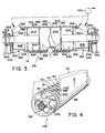
- Figure 3 is a sectional view similar to that shown in Figure 2 but shows an alternative embodiment of the present invention. More particularly, the apparatus 10A includes a perforate roll shell 18A having a first and second end 20A and 22A respectively. The shell 18A defines an elongate chamber 24A which extends between the first and the second ends 20A and 22A respectively.
- a first and second bearing generally designated 34A and 36A respectively cooperate with the first and the second journals 30A and 32A respectively for rotatably supporting the roll shell 18A.
- a housing generally designated 38A is disposed coaxially relative to the shell 18A and adjacent to the first shaft 26A.
- the housing 38A defines a passageway 40A.
- the passageway 40A is connected to a source of partial vacuum 42A.
- a first annular seal means 44A is disposed between the housing 38A and the shaft 26A for sealing the housing 38A relative to the shaft 26A.
- a second annular seal means 46A is disposed between the housing 38A and the shell 18A for sealing the housing 38A relative to the shell 18A such that when the shell 18A rotates relative to the housing 38A, the passageway 40A is sealingly connected to the elongate chamber 24A so that a partial vacuum is generated within the chamber 24A for urging the web WA towards the perforate shell 18A.
- a further housing generally designated 38A1 is disposed coaxially relative to the shell 18A and adjacent to the second shaft 28A.
- the further housing 38A1 defines a further passageway 40A1.
- the further passageway 40A1 is connected to the source of partial vacuum 42A.
- a further first annular seal means 44A1 is disposed between the further housing 38A1 and the shaft 28A for sealing the further housing 38A1 relative to the second shaft 28A.
- a further second annular seal means 46A1 is disposed between the further housing 38A1 and the shell 18A for sealing the further housing 38A1 relative to the shell 18A such that when the shell 18A rotates relative to the further housing 38A1, the further passageway 40A1 is sealingly connected to the elongate chamber 24A so that a partial vacuum is generated within the chamber 24A for urging the web WA towards the perforate shell 18A.
- the roll shell 18A defines a plurality of radial holes 48A, 49A, 50A 48A1, 49A1 and 50A1. Also, the roll shell 18A defines an outer surface 52A. The radial holes extend from the outer surface 52A to the elongate chamber 24A.
- the vacuum guide roll apparatus 10A also includes spider means generally designated 54A and 54A1 which extend between the roll shell 18A and the first and second shafts 26A and 28A respectively for rigidly securing the shafts 26A and 28A coaxially relative to the roll shell 18A.
- the spider means 54A further includes an inner plate 56A which is rigidly secured to the shaft 26A and rigidly secured within the roll shell 18A.
- the inner plate 56A defines an opening 58A such that the passageway 40A is connected to the elongate chamber 24A.
- a further spider means 54A1 includes an inner plate 56A1 which is rigidly secured to the second shaft 28A and rigidly secured within the roll shell 18A.
- the inner plate 56A1 defines a further opening 58A1 such that the further passageway 40A1 is connected to the elongate chamber 24A.
- An outer plate 60A is rigidly secured to the first shaft 26A and to the roll shell 18A.
- the outer plate 60A is spaced axially relative to the inner plate 56A.
- the outer plate 60A defines an orifice 62A so that the passageway 40A is connected to the elongate chamber 24A.
- a further outer plate 60A1 is rigidly secured to the second shaft 28A and to the roll shell 18A.
- the plate 60A1 is spaced axially relative to the inner plate 56A1.
- the outer plate 60A1 defines an orifice 62A1 so that the further passageway 40A1 is connected to the elongate chamber 24A.
- the bearing 34A which is disposed adjacent to the housing 38A, also includes a bearing shell 64A which is rigidly secured to the housing 38A such that the bearing shell 64A and the housing 38A remain stationary while permitting the roll shell 18A and shafts 26A and 28A to rotate relative thereto.
- the bearing 36A is disposed adjacent to the further housing 38A1 and includes a bearing shell 64A1 which is rigidly secured to the housing 38A1 such that the bearing shell 64A1 and the housing 38A1 remain stationary while permitting the roll shell 18A and the shafts 26A and 28A to rotate relative thereto.
- the housing and further housing 38A and 38A1 respectively also include air outlets 66A and 66A1 respectively which are connected to the source of partial vacuum 42A.
- the arrangement is such that in use of the apparatus 10A, air flows as indicated by the arrow 68A, through the shell 18A, the elongate chamber 24A, the passageway and further passageway 40A and 40A1 respectively and the air inlet 66A and 66A1 respectively towards the source of partial vacuum 42A.
- the web WA is therefore urged towards a dryer felt FA and the perforate shell 18A for providing positive restraint of the web WA relative to the felt FA and the roll shell 18A, thereby inhibiting cockling and shrinkage of the web WA during transit of the web WA through the dryer section.
- the partial vacuum in chamber 24A improves the runnability by keeping the web in good contact with the felt.
- the passageways 40A and 40A1 provided at each end of the perforate shell 18 hold the edges of the web and prevent shrinkage of the web. Therefore, by this means, cockle and curl of the web are inhibited.
- Figure 4 is a perspective view partially in section of a vacuum guide roll apparatus according to a further embodiment of the present invention. More particularly, Figure 4 shows a vacuum guide roll apparatus generally designated 10B for guiding a web WB between an upstream dryer and a downstream dryer of a dryer section.
- the apparatus 10B includes a perforate roll shell 18B.
- the arrangement shown in Figure 4 is identical to the embodiment shown in Figure 3 except in that the roll shell 18B is provided with a plurality of circumferential grooves 80, 81, 82, 83 and 84.
- the grooves 80-84 are defined by the outer surface 52B of the roll shell 18B.
- a plurality of radial holes 48B and 49B extertd from an elongate chamber 24B to respective grooves 80 and 81.
- the grooves 80-84 assist in further urging the web WB into close conformity with the felt FB during transit of the web WB around the roll shell 18B.
- the roll shell 18 and shafts 26 and 28 are rotatably supported by means of the bearings 34 and 36.
- the bearing shell 64 being rigidly secured to the housing 38, prevents rotation of the housing 38 relative to the roll shell 18.
- the housing 38 is connected to the source of partial vacuum 42 such that air is drawn through the plurality of holes 48-50 into the elongate chamber 24 and through the passageway 40 for urging the web into close conformity with the dryer felt F so that the web W is constrained against any shrinkage, thereby inhibiting cockling or curl in the resultant web.
- the present invention provides an inexpensive vacuum guide roll that requires no center shaft. Consequently, such guide roll may be supported by smaller bearings and the vacuum is pulled through the roll shell via the stationary housing rather than through passageways defined by the bearing journals.
Landscapes
- Engineering & Computer Science (AREA)
- Textile Engineering (AREA)
- Mechanical Engineering (AREA)
- General Engineering & Computer Science (AREA)
- Paper (AREA)
- Drying Of Solid Materials (AREA)
Applications Claiming Priority (2)
| Application Number | Priority Date | Filing Date | Title |
|---|---|---|---|
| US07/429,592 US4974340A (en) | 1989-10-31 | 1989-10-31 | Vacuum guide roll apparatus |
| US429592 | 1989-10-31 |
Publications (3)
| Publication Number | Publication Date |
|---|---|
| EP0428471A2 true EP0428471A2 (fr) | 1991-05-22 |
| EP0428471A3 EP0428471A3 (en) | 1991-07-10 |
| EP0428471B1 EP0428471B1 (fr) | 1995-11-22 |
Family
ID=23703897
Family Applications (1)
| Application Number | Title | Priority Date | Filing Date |
|---|---|---|---|
| EP90630178A Expired - Lifetime EP0428471B1 (fr) | 1989-10-31 | 1990-10-11 | Rouleau de guidage aspirant |
Country Status (8)
| Country | Link |
|---|---|
| US (1) | US4974340A (fr) |
| EP (1) | EP0428471B1 (fr) |
| JP (1) | JPH0680239B2 (fr) |
| KR (1) | KR0178525B1 (fr) |
| BR (1) | BR9005060A (fr) |
| CA (1) | CA2024990C (fr) |
| DE (1) | DE69023742T2 (fr) |
| FI (1) | FI110623B (fr) |
Cited By (7)
| Publication number | Priority date | Publication date | Assignee | Title |
|---|---|---|---|---|
| AT396263B (de) * | 1991-07-15 | 1993-07-26 | Andritz Patentverwaltung | Saugwalze |
| AT396598B (de) * | 1991-07-15 | 1993-10-25 | Andritz Patentverwaltung | Saugwalze |
| AT397111B (de) * | 1991-12-19 | 1994-02-25 | Andritz Patentverwaltung | Verfahren und vorrichtung zur führung von faserstoffbahnen |
| US5421955A (en) * | 1991-10-28 | 1995-06-06 | Advanced Cardiovascular Systems, Inc. | Expandable stents and method for making same |
| US5546675A (en) * | 1993-11-22 | 1996-08-20 | Beloit Technologies, Inc. | Single tier drying section apparatus |
| WO2002046077A1 (fr) * | 2000-12-07 | 2002-06-13 | Brückner Maschinenbau GmbH | Cylindre aspirant |
| US7947207B2 (en) | 2005-04-12 | 2011-05-24 | Abbott Cardiovascular Systems Inc. | Method for retaining a vascular stent on a catheter |
Families Citing this family (11)
| Publication number | Priority date | Publication date | Assignee | Title |
|---|---|---|---|---|
| FI97245C (fi) * | 1989-12-12 | 1996-11-11 | Valmet Paper Machinery Inc | Paperikoneen imutela |
| WO1997013111A1 (fr) * | 1995-10-04 | 1997-04-10 | Tubular Textile Machinery Corporation | Sechoir aspirant servant a traiter des bandes de tissu, en particulier, des textiles tricotes |
| ATE201070T1 (de) * | 1996-08-22 | 2001-05-15 | Voith Paper Patent Gmbh | Saugwalze zur bildung oder behandlung einer materialbahn wie insbesondere einer papier-, karton- oder textilbahn |
| FI105573B (fi) * | 1996-12-16 | 2000-09-15 | Valmet Corp | Paperikoneen, erityisesti paperin kuivatuslaitteen tela ja paperikoneen kuivatusryhmä |
| KR20010096675A (ko) * | 2001-07-05 | 2001-11-08 | 최정헌 | 다층기능지 제조방법과 장치 및 그 결과물 |
| US6877246B1 (en) * | 2003-12-30 | 2005-04-12 | Kimberly-Clark Worldwide, Inc. | Through-air dryer assembly |
| JP4996820B2 (ja) * | 2004-11-02 | 2012-08-08 | 大王製紙株式会社 | 塗工紙の製造方法及び製造設備 |
| FI118182B (fi) * | 2005-10-25 | 2007-08-15 | Metso Paper Inc | Rainanmuodostuskoneen alipainehihnakuljetin päänvientinauhan viemistä varten |
| US20070193057A1 (en) * | 2006-01-26 | 2007-08-23 | Girolamo Paul A | Rotatable vacuum transfer roll apparatus |
| US10914035B1 (en) | 2019-08-29 | 2021-02-09 | Kimberly-Clark Worldwide, Inc. | Through-air drying apparatus |
| CN113668278B (zh) * | 2021-08-27 | 2022-07-08 | 江苏京环隆亨纸业有限公司 | 一种防损坏的再生纸制造用烘干装置 |
Family Cites Families (8)
| Publication number | Priority date | Publication date | Assignee | Title |
|---|---|---|---|---|
| DE817074C (de) * | 1949-12-14 | 1951-10-15 | Albert Louis Joseph Madeleine | Trockenwalze zum Trocknen eines fuer Gas, Gasgemisch oder Dampf durchlaessigen Stoffes, insbesondere von Papiermaschinenfilzen u. dgl., sowie Verfahren zum Betrieb derselben |
| US2952317A (en) * | 1953-02-27 | 1960-09-13 | Paper Machinery Ltd | Suction moulds |
| DE1254541B (de) * | 1959-06-10 | 1967-11-16 | Voith Gmbh J M | Heissluftblaswalze zum Trocknen luftdurchlaessiger Bahnen, insbesondere Papiermaschinenfilze |
| GB995812A (en) * | 1962-11-26 | 1965-06-23 | Borje Valentin Leckner | Improvements relating to felt drying rollers and the like |
| US3400469A (en) * | 1967-02-27 | 1968-09-10 | Midland Ross Corp | Drier drums comprising annular shell air deflecting collars |
| US4905379A (en) * | 1987-02-13 | 1990-03-06 | Beloit Corporation | Intermediate vacuum roll for dryer |
| US4882854A (en) * | 1987-05-26 | 1989-11-28 | Beloit Corporation | Guide roll apparatus for a dryer of a paper machine drying section |
| FI82096C (fi) * | 1988-01-22 | 1991-12-05 | Tampella Oy Ab | Torkparti i en pappers- eller kartongmaskin och metod foer att leda en bana daeri. |
-
1989
- 1989-10-31 US US07/429,592 patent/US4974340A/en not_active Expired - Lifetime
-
1990
- 1990-09-10 CA CA002024990A patent/CA2024990C/fr not_active Expired - Fee Related
- 1990-10-10 BR BR909005060A patent/BR9005060A/pt not_active IP Right Cessation
- 1990-10-11 DE DE69023742T patent/DE69023742T2/de not_active Expired - Fee Related
- 1990-10-11 JP JP2270634A patent/JPH0680239B2/ja not_active Expired - Fee Related
- 1990-10-11 EP EP90630178A patent/EP0428471B1/fr not_active Expired - Lifetime
- 1990-10-12 FI FI905029A patent/FI110623B/fi not_active IP Right Cessation
- 1990-10-15 KR KR1019900016454A patent/KR0178525B1/ko not_active Expired - Fee Related
Cited By (9)
| Publication number | Priority date | Publication date | Assignee | Title |
|---|---|---|---|---|
| AT396263B (de) * | 1991-07-15 | 1993-07-26 | Andritz Patentverwaltung | Saugwalze |
| AT396598B (de) * | 1991-07-15 | 1993-10-25 | Andritz Patentverwaltung | Saugwalze |
| US5347728A (en) * | 1991-07-15 | 1994-09-20 | Sulzer Escher Wyss Gmbh | Suction roll, especially for a paper web drier |
| US5421955A (en) * | 1991-10-28 | 1995-06-06 | Advanced Cardiovascular Systems, Inc. | Expandable stents and method for making same |
| AT397111B (de) * | 1991-12-19 | 1994-02-25 | Andritz Patentverwaltung | Verfahren und vorrichtung zur führung von faserstoffbahnen |
| US5546675A (en) * | 1993-11-22 | 1996-08-20 | Beloit Technologies, Inc. | Single tier drying section apparatus |
| WO2002046077A1 (fr) * | 2000-12-07 | 2002-06-13 | Brückner Maschinenbau GmbH | Cylindre aspirant |
| US7947207B2 (en) | 2005-04-12 | 2011-05-24 | Abbott Cardiovascular Systems Inc. | Method for retaining a vascular stent on a catheter |
| US8221112B2 (en) | 2005-04-12 | 2012-07-17 | Abbott Cardiovascular Systems, Inc. | Method for retaining a vascular stent on a catheter |
Also Published As
| Publication number | Publication date |
|---|---|
| EP0428471B1 (fr) | 1995-11-22 |
| DE69023742D1 (de) | 1996-01-04 |
| BR9005060A (pt) | 1991-09-17 |
| EP0428471A3 (en) | 1991-07-10 |
| FI110623B (fi) | 2003-02-28 |
| JPH0680239B2 (ja) | 1994-10-12 |
| CA2024990C (fr) | 1993-05-18 |
| CA2024990A1 (fr) | 1991-05-01 |
| DE69023742T2 (de) | 1996-07-04 |
| FI905029A0 (fi) | 1990-10-12 |
| KR0178525B1 (ko) | 1999-05-15 |
| JPH03146787A (ja) | 1991-06-21 |
| KR910007782A (ko) | 1991-05-30 |
| US4974340A (en) | 1990-12-04 |
Similar Documents
| Publication | Publication Date | Title |
|---|---|---|
| US4974340A (en) | Vacuum guide roll apparatus | |
| CA1336942C (fr) | Rouleau de guidage pour sechoir de section de sechage de machine a papier | |
| US4693784A (en) | Suction roll and method for applying a negative pressure over a sector of a roll | |
| EP0617162B1 (fr) | Cylindre pour machine à papier | |
| CA1224007A (fr) | Calandre de traitement par pression et par voie thermique | |
| CA1313788C (fr) | Dispositif de transfert | |
| CA1304934C (fr) | Cylindre de transfert a succion pour secherie | |
| JP3036585B2 (ja) | 抄紙機又は塗工機内のカレンダ | |
| US4566946A (en) | Transfer arrangement for guiding the paper web from the press section of a paper machine to it's drying section | |
| US3013487A (en) | Apparatus for tension control | |
| US4932138A (en) | Method and device for threading a web around drying cylinders | |
| KR100191142B1 (ko) | 펠트 회전 롤 | |
| KR100294803B1 (ko) | 단층형 건조부 장치 | |
| US5020238A (en) | Vacuum guide roll apparatus | |
| CA2211171C (fr) | Secheur pour machine a papier avec enceinte a depression a plusieurs rouleaux | |
| US4835881A (en) | Dryer section apparatus | |
| US6616813B2 (en) | Pressing arrangement | |
| EP0069667B1 (fr) | Presse aspirante à plusieurs interstices de pressage | |
| EP0368937B1 (fr) | Secheuse | |
| WO1996023931A1 (fr) | Appareil de transfert de nappe | |
| US20070272384A1 (en) | Suction or Ventilation Roll | |
| JPS595717B2 (ja) | 抄紙機等における乾燥ロ−ル | |
| WO1998054404A1 (fr) | Appareil a presse a pince allongee |
Legal Events
| Date | Code | Title | Description |
|---|---|---|---|
| PUAI | Public reference made under article 153(3) epc to a published international application that has entered the european phase |
Free format text: ORIGINAL CODE: 0009012 |
|
| AK | Designated contracting states |
Kind code of ref document: A2 Designated state(s): DE FR GB IT SE |
|
| PUAL | Search report despatched |
Free format text: ORIGINAL CODE: 0009013 |
|
| AK | Designated contracting states |
Kind code of ref document: A3 Designated state(s): DE FR GB IT SE |
|
| 17P | Request for examination filed |
Effective date: 19920107 |
|
| 17Q | First examination report despatched |
Effective date: 19940622 |
|
| GRAA | (expected) grant |
Free format text: ORIGINAL CODE: 0009210 |
|
| AK | Designated contracting states |
Kind code of ref document: B1 Designated state(s): DE FR GB IT SE |
|
| REF | Corresponds to: |
Ref document number: 69023742 Country of ref document: DE Date of ref document: 19960104 |
|
| ITF | It: translation for a ep patent filed | ||
| ET | Fr: translation filed | ||
| REG | Reference to a national code |
Ref country code: FR Ref legal event code: TP |
|
| REG | Reference to a national code |
Ref country code: GB Ref legal event code: 732E |
|
| PLBE | No opposition filed within time limit |
Free format text: ORIGINAL CODE: 0009261 |
|
| STAA | Information on the status of an ep patent application or granted ep patent |
Free format text: STATUS: NO OPPOSITION FILED WITHIN TIME LIMIT |
|
| 26N | No opposition filed | ||
| REG | Reference to a national code |
Ref country code: GB Ref legal event code: IF02 |
|
| PGFP | Annual fee paid to national office [announced via postgrant information from national office to epo] |
Ref country code: GB Payment date: 20030929 Year of fee payment: 14 |
|
| PGFP | Annual fee paid to national office [announced via postgrant information from national office to epo] |
Ref country code: SE Payment date: 20031001 Year of fee payment: 14 |
|
| PGFP | Annual fee paid to national office [announced via postgrant information from national office to epo] |
Ref country code: FR Payment date: 20031009 Year of fee payment: 14 |
|
| PGFP | Annual fee paid to national office [announced via postgrant information from national office to epo] |
Ref country code: DE Payment date: 20031010 Year of fee payment: 14 |
|
| PG25 | Lapsed in a contracting state [announced via postgrant information from national office to epo] |
Ref country code: GB Free format text: LAPSE BECAUSE OF NON-PAYMENT OF DUE FEES Effective date: 20041011 |
|
| PG25 | Lapsed in a contracting state [announced via postgrant information from national office to epo] |
Ref country code: SE Free format text: LAPSE BECAUSE OF NON-PAYMENT OF DUE FEES Effective date: 20041012 |
|
| PG25 | Lapsed in a contracting state [announced via postgrant information from national office to epo] |
Ref country code: DE Free format text: LAPSE BECAUSE OF NON-PAYMENT OF DUE FEES Effective date: 20050503 |
|
| EUG | Se: european patent has lapsed | ||
| GBPC | Gb: european patent ceased through non-payment of renewal fee |
Effective date: 20041011 |
|
| PG25 | Lapsed in a contracting state [announced via postgrant information from national office to epo] |
Ref country code: FR Free format text: LAPSE BECAUSE OF NON-PAYMENT OF DUE FEES Effective date: 20050630 |
|
| REG | Reference to a national code |
Ref country code: FR Ref legal event code: ST |
|
| PG25 | Lapsed in a contracting state [announced via postgrant information from national office to epo] |
Ref country code: IT Free format text: LAPSE BECAUSE OF NON-PAYMENT OF DUE FEES;WARNING: LAPSES OF ITALIAN PATENTS WITH EFFECTIVE DATE BEFORE 2007 MAY HAVE OCCURRED AT ANY TIME BEFORE 2007. THE CORRECT EFFECTIVE DATE MAY BE DIFFERENT FROM THE ONE RECORDED. Effective date: 20051011 |