EP0428499A2 - Dispositif de méthode de détection de l'écartement de caractères pour des systèmes de lecture optique de caractères - Google Patents
Dispositif de méthode de détection de l'écartement de caractères pour des systèmes de lecture optique de caractères Download PDFInfo
- Publication number
- EP0428499A2 EP0428499A2 EP91100048A EP91100048A EP0428499A2 EP 0428499 A2 EP0428499 A2 EP 0428499A2 EP 91100048 A EP91100048 A EP 91100048A EP 91100048 A EP91100048 A EP 91100048A EP 0428499 A2 EP0428499 A2 EP 0428499A2
- Authority
- EP
- European Patent Office
- Prior art keywords
- character
- pitch
- section
- lumps
- candidate
- Prior art date
- Legal status (The legal status is an assumption and is not a legal conclusion. Google has not performed a legal analysis and makes no representation as to the accuracy of the status listed.)
- Granted
Links
Images


Classifications
-
- G—PHYSICS
- G06—COMPUTING OR CALCULATING; COUNTING
- G06V—IMAGE OR VIDEO RECOGNITION OR UNDERSTANDING
- G06V30/00—Character recognition; Recognising digital ink; Document-oriented image-based pattern recognition
- G06V30/10—Character recognition
- G06V30/14—Image acquisition
- G06V30/148—Segmentation of character regions
- G06V30/158—Segmentation of character regions using character size, text spacings or pitch estimation
-
- G—PHYSICS
- G06—COMPUTING OR CALCULATING; COUNTING
- G06V—IMAGE OR VIDEO RECOGNITION OR UNDERSTANDING
- G06V30/00—Character recognition; Recognising digital ink; Document-oriented image-based pattern recognition
- G06V30/10—Character recognition
Definitions
- the present invention relates to optical character reader systems. More particularly, it is concerned with a character pitch detector apparatus for detecting a character pitch of a series of character string images given on paper.
- the optical character reader systems are required to separate the characters one by one. Further, the optical character reader systems are desirable to manage printed characters of many font types and poor print quality which are printed on general mails and documents.
- a character string printed on general documents there is a case where the characters to be separated touch each other, or one character is separated into more than one images due to the poor print quality.
- each character width varies according to a variance in the font or character category. Therefore, a sectioning apparatus is necessary, which can properly section the character string into individual characters under the above-mentioned conditions.
- This type of sectioning apparatus has been proposed in U.S. Patent No. 3,629,826.
- the proposed sectioning apparatus scans a character image vertically and sets a character segmentation position by detecting a position where a vertical scan bit is minimized.
- this apparatus stores many touching images for every characters in advance, and a segmentation position is determined by comparing the touching character image with the stored touching images. That is, this apparatus performs the character segmentation referring to the local images of the character string.
- sectioning apparatus cannot properly segment the character splited into two or more images as one character. Additionally, this apparatus requires a vast memory capacity for storing many touching images of every characters touching other characters. Furthermore, a special function for character segmentation in accordance with an individual case may invite a considerable deterioration in precision and speed of the character segmentation.
- this type of sectioning apparatus can use a character pitch as information for segmenting a character string.
- the character pitch can be given to the sectioning apparatus as known information by limiting printed matters to be read by an optical character reader.
- the character pitch cannot be known beforehand. Accordingly, the character pitch must be estimated from a character string image on the paper.
- a mean value of character widths of various characters is used as estimated value for the character pitch.
- an error between the mean value of character widths and an actual character pitch can no more be negligible. Due to the error, the sectioning apparatus mistakes the number of touching characters or cuts off the character string at an incorrect position for segmentation.
- the optical character reader is desired to manage both the characters printed at constant pitch and printed at variable pitch including hand-written characters. In such a case, the sectioning apparatus must change the algorithm for character segmentation according to the constant pitch-printed characters and the variable pitch-printed characters. Therefore, it is also important to identify whether the pitch of the obtained character data is constant or variable before performing segmentation of character string.
- an object of the present invention is to provide a character ptich detector apparatus capable of detecting a character pitch of a series of character string images with precision even in the case that the character string includes touching characters, or one character is splited into two or more images.
- Another object of the present invention is to provide a novel character pitch detecting method.
- Still further object of the present invention is to provide an apparatus capable of identifying whether an obtained character data has a constant pitch or variable pitch.
- an apparatus estimating a character pitch This apparatus separate a frequency distribution of a character lump on a distance between the character lumps into a plurality of sections by means of a candidate character pitch.
- the character lumps are separated by the blank space information of character image.
- the candidate character pitch is set by means of a character height informations or others.
- the apparatus works out an optimal linear form sum appreciation standard (variance criterion) of the error between a representative point of the separated section and the candidate character pitch.
- the most appropriate character pitch is so determined that it minimizes the optimal linear form sum appreciation standard (variance criterion).
- Fig. 1 (a) shows a character string image including touching characters and one character splited into two images in oblique lines.
- a character pitch P may be obtained by a character pitch detector described hereinafter, but if it is known already, then the known value can be used.
- a projection distribution shown in Fig. 1 (b) is obtained through projecting vertically the character string image of Fig. 1 (a).
- a segmenting start position of the character In order to separate the touching characters (a m u) and the split character (h) into a correct unit of individual character, a segmenting start position of the character must be predicted correctly. For example, in the touching character images "a” and “m”, "a" is slightly smaller. Therefore, the segmenting start position should be set slightly leftward from a leading end of the touching character images (a m u).
- a white area hereinafter called a blank space
- a black area hereinafter called a character lump
- permissible section sections for setting the character segmentation positions are set by means of the character pitch P and preset thresholds T, and T 2 under following conditions (1) and (2).
- the permissible section satisfying the above conditions (1) and (2) comes in, as shown in Fig. 1 (d). sections A 0 , A 1 , A 2 , A3, Aa and A 5 .
- the above thresholds T. and T 2 may be given as functions of the character pitch P.
- the threshold T 1 may be set according to an estimate error arising from estimating the character pitch P as described later.
- segmentation candidate sections k (k 0) shown in Fig. 1 (e) are set in the permissible sections A., A 2 , A3, Aa and As by using the character pitch P and preset threshold T 3 .
- first scan bits W o ' (indicated by white dots) are set in the blank space We.
- a section k' 0 in which a distance from the arbitrary scan bit Wo' satisfies(P ⁇ T 3 )is set.
- a segmentation candidate position hereinafter, which is expressed as x(k, i k ).
- i k is an integer starting from 1, which is a relative number in the segmentation candidate section k. That is, the first segmentation candidate position x(0, 1) is detected in this stage.
- the distance d(1,2; 1,2) between the segmentation candidate positions x(1, 1) and x(2, 2) satisfies the following formula:
- the white dots existing within the permissible section A3 are two, and a segmentation candidate position x(1, i k )is obtainable as two positions x(1, 1) and x(1, 2).
- the above-described threshold T 3 can be given as a function of the character pitch P like the threshold T 1 .
- the segmentation candidate section k can also be set under another condition by means of the character pitch P, the character lump width Vi, and the blank space Wi.
- a method for detecting a trailing end of the character string image will be described hereinafter. As will be described later, the trailing end detection is necessary for determining a segmentation position of the character string.
- the character image is disintegrated into the character lump Vi and the blank space Wi.
- Each blank space Wi is compared with the product T 4 ⁇ P, i.e., the product of a preset parameter T 4 and the character pitch P.
- a blank space W 1 greater than the product T 4 ⁇ P is set as a first trailing end candidate section.
- the product T 5 ⁇ P i.e.. the product of a preset parameter T; (T 5 ⁇ T 4 ) and the character pitch P is calculated.
- the section from a leading end of trailing end candidate section W 1 to the position determined by the product T 5 ⁇ P is set as a first trailing end permissible section.
- the section from a leading end of a character lump V 1 present immediately before the candidate section W 1 to the position determined by the sum P+T ⁇ (the sum of the character pitch P and the parameter T.) is set as a second trailing end permissible section.
- a logical sum of the first and second trailing end permissible sections T 5 ⁇ P and P+T. is set as a second trailing end candidate section Q.
- a trailing end section E is determined by working out the logical product of the first candidate section W 1 and the second candidate section Q. That is, in Fig. 2 (a), the trailing end section E is equal to the section T5 ⁇ P, and in Fig. 2 (b), the trailing end section E is equal to the section W 1 .
- the trailing end section E of the Fig. 1 (e) includes the segmentation candidate positions x(4, 2), x(4, 3) and x(4, 4).
- the trailing end section can be set in other manner.
- the blank space of a trailing end of the character line may be set as a trailing end section.
- a segmentation candidate section (k + 1) is set by using of the segmentation candidate section k, and if the segmentation candidate position x-(k+1, i k+1 )satisfying the formula (1) is not in a permissible section A i , then the segmentation candidate section k may be set as the trailing end section.
- the leading end of the segmentation candidate section can be set according to the position of the trailing end section which has already detected.
- positions indicated by a black dot represent each segmentation candidate position x(k, i k )shown in Fig. 1 (e) with the scan pitch given at 1 and the position x(0, 1) working as an origin.
- the character pitch P is set at "20".
- a symbol (r, n; i n i n )(0 ⁇ r ⁇ n) denotes a variance in the mean value ⁇ d (r, n; i,, i n )of (n - r) pieces of distances d(r, r + 1; i r , i r+1 ), d(r+1, r+2, i r+1 , i r+2 ), .... d(n-1, n; i n-1 , in).
- the weighting factor ⁇ in the formula (2) satisfies 0 ⁇ ⁇ ⁇ 1.
- the segmentation candidate position for minimizing the formula (2) can be determined according to the following dynamic programming.
- An optimum segmentation candidate position x(k, i k )in the segmentation candidate section k is obtained according to the following recurrence formulas (3-1), (3-2) and (3-3).
- a distance d(k, k+1: i k , i k+1 ) is calculated first, and then the following formulas (3-1), (3-2) and (3-3) are calculated.
- the segmentation candidate position x'(k, i k )minimizing the appreciation standard U(0, k+1) of the formula (3-3) becomes an optimum segmentation candidate position to the arbitrary segmentation candidate position x(k+1, i k+1 )of the segmentation candidate section (k+1) in h k pieces of segmentation candidate positions x(k, 1), .... x(k, h k )of the segmentation candidate section k.
- the optimum mean value ⁇ d (0, 0; io, io) indicated in the formula (3-1) is zeroised, and a square cumulative sum D*(0) of the optimum distance d(-1, 0; i-,, io) indicated in the formula (3-2) is zeroised.
- An optimum segmentation candidate position x(k; i k )of the segmentation candidate section k in each segmentation candidate position x(k+1, i k+1 ) of the next segmentation candidate section (k+1) can be obtained by storing an optimum mean value ⁇ * d (0, 1; i k , io) and a square cumulative sum D * (k-1, k)of the optimum distance d(k-1, k; i k-1 , i k )at each segmentation candidate position x(k, i k )of the segmentation candidate section k.
- the first term of the formula (3-3) represents another method for expressing the variance ad (0, k+1; io, i k+1 ) shown in the formula (2).
- an appreciation standard U(0, 2) at the segmentation candidate position x(2, 1) in a path through the segmentation candidate position x(2, 1) is 1.26.
- One of the segmentation candidate positions x(4, 2), x(4, 3) and x(4, 4) whose appreciation standard U(0, 4) is minimum is selected as an end position of the character segmentation. Accordingly, the position x(4, 2) is selected as the end position because its appreciation standard is 20.3 while others are 20.5 and 20.8.
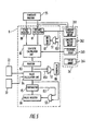
- a logical block for the above processing is shown in Fig. 4.
- a scanner 1 scans a character string image printed on a sheet of paper optically and transforms it into an electrical signal.
- the character string image is binary-quantized and stored in a character string image memory 2.
- a character lump extraction unit 3 extracts character lumps of the character string image out of the character string image memory 2 in sequence and stores position, width and height of each character lump Vi to a character lump information register 21.
- Such character lump extraction unit 3 can be realized according to a known technique.
- a character pitch detector 4 estimates the character pitch P by means of position, width and height of each character lump Vi stored in the character lump information register 21. The estimated character pitch is stored to a character pitch information register 22.
- the character pitch detector 4 will be described in detail hereinafter.
- a parameter information register 30 stored parameters T i , T 2 , T 3 , T 4 , T s , ⁇ which are various thresholds and weighting factor as described hereinbefore.
- a permissible section extraction unit 5 extracts the permissible sections Ai satisfying the above-described condition (1) and condition (2).
- the positions and height of the section Wi are extracted by a comparator or others referring to the position and width Vi of a plurality of character lumps stored in the character lump information register 21.
- each character lump width Vi is compared with the sum P + Ti of the character pitch P stored in the character pitch information register 22 and the parameter T 1 stored in the parameter information register 30. If the width Vi is larger than the sum P + Ti, a value T 2 stored in the parameter information register 30 is excepted from both ends of the character lump width Vi, and the permissible section satisfying the condition (2) is extracted.
- the position and width of the permissible sections Ai are stored in a permissible section information register 23.
- a trailing end candidate section extraction unit 6 calculates the product T 4 ⁇ P of the parameter T 4 stored in the parameter information register 30 and the character pitch P. Then, the unit 6 compares the product T4 ⁇ P with the blank space Wi stored in the permissible section register 23. The blank space W j having a width larger than the product T 4 ⁇ P is thus detected as a first trailing end candidate section. Next, the extraction unit 6 calculates the product T 5 ⁇ P of the parameter T 5 and the character pitch P, and sets the section from a leading end of the blank space W i to the position determined by the product T 5 ⁇ P as a permissible section.
- the sum P+T, of the character pitch P and the parameter T 1 is calculated, and the permissible section from a leading end of the character lump V j immediately before the bank space W j to the sum P+T 1 is set.
- the two permissible sections are subjected to a logical sum and stored in sequence in a trailing end candidate section register 24 as a second trailing end candidate section.
- a segmentation candidate section extraction unit 7 extracts each segmentation candidate position x(k, i k )of the segmentation candidate section k in sequence with reference to the permissible sections Ai and parameters stored in the permissible section information register 23 and the parameter information register 30 respectively.
- These positions x(0, io) are calculated based on each segmentation candidate position in a constant range of blank space Wo'.
- the blank space Wo ' is set according to the character pitch P from a leading end of the character string image.
- the segmentation candidate positions x(0, io) are stored to an optimum segmentation position information register 26.
- a segmentation candidate section extraction unit 7 calculates a segmentation candidate position x(k+1, i k+1 ) satisfying the expression (1).
- a position (x(k, h k ) + P + T 3 ) is calculated using the last segmentation candidate position x(k, h k )of the segmentation candidate section k, the character pitch P and the parameter T 3 .
- the mean value ⁇ * d (0, k; i o , i k ) calculated by the appreciation standard arithmetic operation unit 8 according to the formula (3-1), the square cumulative sum D*(k) of a distance calculated according to the formula (3-2), and the appreciation standard U(0, k) and the optimum segmentation candidate position x*(k-1, i k-1 )of the segmentation candidate section k-1 calculated according to the formula (3-3) has already stored in the register 26. These data are stored at the area correspondingly to each segmentation candidate position x(k, i k ) (i k 1, .... h k ).
- h k pieces of the appreciation standard U(0, k+1) relating to the segmentation candidate positions x(k, i k )of the segmentation candidate section k are obtained through calculating the recurrence formulas (3-1), (3-2) and (3-3) in sequence.
- the mean value ⁇ * d (0, 1; io, i k ), square cumulative sum D"(k) of the distance and parameter ⁇ stored in the parameter information register 30 are referred.
- the minimum value of the appreciation standard U * (0, k + 1) is defected, and the segmentation candidate position x"(k, i k )corresponding to the minimum standard U*(0, k + 1) is selected as an optimum segmentation candidate position.
- the optimum segmentation candidate x*(k, i k ) is a precedent point reaching to the segmentation candidate position
- minimum value of the appreciation standard U(0, k + 1), mean value whereat the appreciation standard U(0, k + 1) is minimized in value, and square cumulative sum D*(k+1) of the distance are stored to the optimum segmentation position information register 26 together with the segmentation candidate position x*(k+1, i k+1 ).
- the appreciation standard arithmetic operation unit 8 performs the above-described operation for all the segmentation candidate positions x(k+1, i k+1 ).
- control unit 10 instructs the segmentation candidate section extraction unit 6 for extraction of the segmentation candidate positions x(k+2, i k+2 )of the next segmentation candidate section k+2.
- the same operation to the above-described is repeated.
- the control unit 10 then checks whether or not the segmentation candidate position x(k+1, i k+1 )of the segmentation candidate section (k + 1) transferred to the optimum segmentation position information register 26 has reached the trailing end candidate section.
- the information of the trailing end candidate section is stored in the trailing end candidate section register 24. If not, then only an instruction on processing to the next segmentation candidate section is outputted to the segmentation candidate section extraction unit 6.
- the control unit 10 detects the segmentation candidate positions x(e, i e )included in the trailing end candidate section E. Then, the control unit 10 calculates a plurality of the appreciation standard U(0, n) relating to he pieces of the segmentation candidate positions x(e, i e ). The minimum appreciation standard U'(0, n) is detected, and the segmentation candidate position x'(e, i e )corresponding to the appreciation standard U*(0, n) is selected as a trailing end position.
- the control unit 10 further detects a sequence of optimum segmentation candidate positions reaching the segmentation candidate position x*(n, in). This detection is carried out referring to the optimum segmentation position information register 26. That is, the sequence of the optimum segmenting position is selected by tracing the optimum path reversely from the trailing end position x*(n, in)to the segmentation candidate positions x"(n-1, in-1), .... x*(0, io) in sequence.
- the segmenting positions thus detected, are stored in a character segmenting position register 27.
- control unit 10 detects a constant range set according to the character pitch P within the blank space from the trailing end position x"(n, in)to a leading end of the next character lump.
- the position of the leading end is stored to the optimum segmenting position information register 26.
- character segmenting positions of the character string image are stored to the character segmenting position register 27.
- the character string image is segmented per character by means of the height of each character lump stored in the character lump information register 21 and the character segmenting position stored in the character segmenting position register 27. Segmented characters are read by a known character recognition system.
- segmentation candidate positions x(k + 1, i k+1 )of the segmentation candidate section k + 1 are stored in the segmentation candidate position information register 25, the segmentation candidate positions x(k+1, i k+1 )is transferred to a distance calculation unit 81 and a segmentation candidate position group register 261 at appropriate positions.
- the segmentation candidate section (k + 1) is stored in a stage register 80 and the segmentation candidate position group register 261 at predetermined positions.
- the optimum segmentation position information register 26 comprises the segmentation candidate position group register 261, a concatenation information group register 262, an optimum statistic group register 263 and an optimum appreciated value group register 264.
- the distance calculation unit 8 calculates a distance d(k, k + 1; i k , i k+1 )in sequence.
- a statistic calculation unit 82 calculates a mean value p d (0, k+1; io, i k+1 )and a square cumulative sum D(k) of the distance according to the recurrence formulas (3-1) and (3-2). That is, the mean value p d (0, k+1; io, i k+1 )is calculated according to the expression (3-1) by means of the mean value ⁇ * d (0, k; io, i k ) at the segmentation candidate position x(k, i k )stored in the optimum statistic group register 263, the distance d(k, k+1; i k , i k+1 )calculated in the distance calculation unit 81, and segmentation sections (k+1) and k stored in the stage register 80.
- the square cumulative sum D(k + 1) of the distance is calculated according to the formula (3-2) by means of the square cumulative sum D"(k) of the distance at the segmentation candidate position x(k, i k )stored in the optimum statistic group register 263 and the distance d(k, k + 1; i k , i k+1 )put out from the distance calculation part 81.
- the mean value ⁇ d (0, k + 1; io, i k+1 )and the square cumulative sum D(k + 1) of the distance are calculated by the statistic calculation unit 82. These data are stored to a statistic loading register 83.
- An appreciated value calculation unit 84 calculates a value of the appreciation standard U(0, k + 1) according to the formula (3-2). That is, the appreciated value U(0, k + 1 ) is calculated according to the formula (3-3) by means of the character pitch P, the parameter p, a content of the statistic loading register 83, and a content of the stage register 80.
- a comparator 85 compares an appreciated value put out from the appreciated value calculation unit 84 with a content of a minimum appreciated value register 86. If the output of the appreciated value calculation unit 84 is smaller than the content of the minimum appreciated value register 86, an output signal 851 turns "ON". Initially, a sufficiently large value is set in the minimum appreciated value register 86.
- a gate circuit 53 opens, and an output of the appreciated value calculation part 84 is transferred to the minimum appreciated value register 86. Further, when the output signal 851 turns “ON”, a gate circuit 52 opens, and the mean value ⁇ d (0, k+1, io, i k+1 )and the square cumulative sum D(k+1) of the distance stored in the statistic loading register 83 are transferred to a minimum statistic register 88. Furthermore, when the output signal 851 turns "ON", a gate Circuit 51 opens, position informations k and i k at the segmentation candidate position x(k, i k )stored in the distance calculation part 81 are transferred to a concatenation information register 87.
- the optimum mean value ⁇ *(0, k+1; io, i k-1 )and the square cumultive sum D*(k+1) at the segmentation candidate position x(k+1, i k-1 ) are stored to the minimum statistic register 88.
- An optimum appreciated value of the segmentation candidate position x(k+1, i k+1 ) is stored to the minimum appreciated value register 86.
- an optimum segmentation path information to the segmentation candidate position x(k + 1, i k )from the segmentation candidate section x(k, i, ) is stored in the concatenation information register 87.
- the minimum appreciated value register 86 Contents of the minimum statistic register 88, the minimum appreciated value register 86 and the concatenation information register 87 are respectively transferred to the minimum statistic group register 263, the minimum appreciated value group register 264 and the concatenation information group register 262 by the control part 10. Next, the minimum appreciated value register 86 is initialized sufficiently large.
- the character sectioning apparatus as described above can sectioning a character string into indivisual characters easily and stably even if the character string includes touching characters and one character is splited into two or more images.
- Fig. 6 represents a character string image for describing a distance between character lumps.
- the character lump is indicated by oblique lines and is given in a rectangular area (broken line).
- the symbols representing a distance between the character lumps can be utilized as observed values constituting a frequency distribution of a distance between the character lumps.
- a reference symbol F' i,j represents a distance from a trailing end of the i-th character lump to a trailing end of the j-th character lump.
- character images such as period (.), comma (,) and the like can be removed from observation of the distance between character lumps by checking the character lump width and height by means, for example, of a mean height H m of a plurality of character lumps. When a large blank space as compared with the means height H m is detected, the distance between character lumps including the blank space can be removed from the observation.
- Fig. 7 is one example of a frequency distribution of the distance between a series of character lumps having a constant pitch character as shown in Fig. 6.
- An axis F of abscissas the indicates a value of the distance F i , j
- an axisNUM of ordinates indicates a frequency of the distance between character lumps.
- Figs. 8 (a) and 8 (b) represent an example of a frequency distribution of the distance between a series of character lumps in a constant pitch data and an alphabetical variable pitch data, respectively.
- the mean character height H m is calculated according to the heights of a plurality of character lumps.
- a presence candidate section ( ⁇ 1 ⁇ H m , ⁇ 2 ⁇ H m )of the character pitch is set by means of coefficients ⁇ 1 a 2 ( ⁇ 1 ⁇ ⁇ 2 ). All distances between the character lumps existing in the presence candidate section ( ⁇ 1 ⁇ Hm, ⁇ 2 ⁇ Hm) can be regarded as candidate character pitches P,, however, number of the candidate character pitches P, can be reduced according to the following processing in order to save a processing time.
- a distance F(1) between character lumps which takes the most frequent distance within a constant permissible width ⁇ is calculated by means of the frequency distribution within the presence candidate section ( ⁇ 1 ⁇ H m , ⁇ 2 ⁇ Hm).
- a lower bound value of a limited presence candidate section of the character pitch P is set as MAx( ⁇ Hm, (1- ⁇ 3 ) ⁇ F(1))by means of a coefficient a3 (0 ⁇ ⁇ 3 ⁇ 1).
- An upper bound value of the limited presence candidate section of the character pitch is set as MIN( ⁇ 2 ⁇ H m , (1 + ⁇ 3 ) ⁇ U(1)).
- a section c. is the limited presence candidate section of the character pitch. and a plurality of distance between character lumps included in the section C. are as the candidate character pitches P i .
- the frequency distribution is divided into areas f' 1 , f' 2 , ... f' n as indicated by a broken line.
- a boundary point S(f' k , f' k-1 )of each area f' k is present at middle of a center k' ⁇ P 1 of the area f' k and a center (k+1) ⁇ P, of the area f' k+1 .
- the boundary point S(f' k-1 , f' k ) is expressed as(kP, - P,)and the boundary point S(f' k , f' k-1 )is expressed as(kP, + 1 2 P,)
- a quantity corresponding to the character pitch observed from the area f' k based on the candidate character pitch P, is detected by dividing the mean value P(k, n k )by an integer k.
- An estimated character pitchP can be obtained by means of an optimal linear estimating technique.
- a plurality of difference between a value ⁇ P(k ⁇ n k )observed from the area f' k and the candidate character pitch P i converting all the area f' k are calculated. Then, the candidate character pitch P; minimizing the difference is selected as an estimated character pitch P.
- the following pitch estimation error appreciation standard (variance criterion) T which works as the appreciation standard for optimal estimation is employed.
- the estimation error appreciation standard T of the formula (4) is a variance of estimation error.
- an appreciation standard based on an absolute value of the difference may be employed.
- the optimum estimated character pitch can be obtained by means of formula (4). Further, the frequency distribution of the distance between character lumps is also clustered at the same time.
- a character pitch identifying technique will be described with reference to Figs. 7, 8(a) and 8(b).
- the frequency distribution of the distance between character lumps having a constant pitch printed character (Fig. 8 (a)) is different from that having a variable pitch printed character (Fig. 8 (b)).
- n will be employed: where the coefficient C'(k, n k )at the variance appreciated value e 2 is a function of the sample number n k of the distance between character lumps and the integer k, and which satisfies As an example of this coefficient, can be employed.
- an error appreciated value ⁇ can be used instead of the above-described variance appreciated value ⁇ 2 .
- the character string can be segmented by means of the estimated character pitchP as a main component, namely, the character string has a constant character pitch. If the variance appreciated value ⁇ 2 or the error appreciated value ⁇ is less than the threshold ⁇ 4 , the character string cannot be segmented by means of mainly the estimated character pitch P, namely, the character string has a variable character pitch.
- the character pitch can be identified.
- a stable character segmentation will be ensured by the character sectioning apparatus shown in Fig. 4, in the case that the character string has a constant character pitch.
- the characters can be segmented according to other character segmentation technique based on a blank space of the character line image, for example.
- Fig. 9 is a block diagram of a character pitch detector.
- a leading edge position and a size of each character lump are stored to the character lump register 21 by means of the scanner 1, the character string image memory 2 and the character lump extraction unit 3.
- the size of the character lump means a width and a height of the character lump.
- An another control unit 41 calculates a distance between character lumps by means of a leading end position and a trailing end position of the character lumps. The leading and trailing end positions are transferred in sequence from the character lump register 21. Then, the control unit 41 increases a frequency corresponding the distance between character lumps.
- the frequency is stored in a frequency distribution table 42 at an address position indicating the distance between character lumps.
- the frequency distributions of the distance between character lumps as shown in Figs. 7, 8(a) and 8(b) are generated in the frequency distribution table 42.
- the frequency distribution table 42 is initialized at 0 at first.
- the control unit 41 calculates the mean height H m by means of a plurality of height of a plurality of character lumps stored in the character lump register 21.
- the mean height H m is transferred to a presence section detector 43.
- a constant register 44 stores the coefficients ⁇ 1 , a 2 (ai ⁇ a 2 ) and ⁇ 3 and the constant permissible width ⁇ .
- the presence section detector 43 inputs the coefficients a 1 and a 2 from the constant register 44 at first, and then sets the lower bound value ⁇ 1 H m and the upper bound value ⁇ 2 H m of a presence candidate section of the character pitch.
- the presence section detector 43 reads a frequency value of the distance between character lumps belonging to the presence candidate section in sequence from the frequency distribution table 42 via the control unit 41. According to the read frequency value, the distance F(1) between character lumps which takes the most frequent distance within the constant permissible width ⁇ is calculated.
- a presence section arithmetic operation unit 45 calculates values (1- ⁇ 3 ) ⁇ F(1) and (1 + ⁇ 3 ) ⁇ F(1) by means of the distance F(1) by means of the presence section detector 43 and the coefficient a 3 from the constant register 44. Then, the arithmetic operation unit decides MAX ⁇ 1 ⁇ Hm, (1 -a3) ⁇ F(1) ⁇ and MIN ⁇ a 2 ⁇ H m , (1 +a3). F(1) ⁇ as a lower bound value P L of the character pitch limited presence candidate section C. and an upper bound value P u of the limited presence candidate section C 1 . The lower and upper bound values P L and P u are stored to a presence section register 46. If the distance F(1) is not detected in the presence section detector 45, the mean height H m is set instead of the distance F(1).
- the lower bound value P L of the character pitch is transferred from the presence section register 46 to a counter 47.
- the counter 47 is counted from the lower bound value P L up to the upper bound value P u in sequence after, the operation described below is finished, and transfers the count value P, (P L ⁇ P, ⁇ P u )to a mean value calculation unit 48.
- the means value calculation unit 48 calculates a number n k and mean value P(k, n)of the distance between character lumps belonging to the area f k with reference to the frequency distribution table 42. The above processing is carried out covering n pieces of areas.
- the estimation error appreciated value arithmetic operation unit 49 computes the estimation error appreciated value T (formula (4)) by means of the information transferred from the mean value calculation unit 48.
- a minimized estimation error appreciated value T is stored to an appreciated value register 50. Initially, a sufficiently large value is set in an optimum character pitch register 54 as the estimation error appreciated value.
- a comparison unit 55 compares the estimation error appreciated value T transferred from the estimation error appreciated value arithmetic operation unit 49 with a content of the appreciated value register 50. When an output value of the estimation error appreciated value arithmetic operation unit 49 is smaller than the content of the appreciated value register 50, the comparison unit 55 writes the output value of the estimation error appreciated value arithmetic operation unit 49 in the appreciated value register 50, and writes a value of the candidate character pitch P i in the optimum character pitch register 54. Then, the comparison unit 49 advances the counter 47 by 1 via the control unit 41.
- the comparison part 55 only advances the counter 47 by 1.
- the optimum character pitchP will be obtained in the optimum character pitch register 54 by carrying out the above operation until a value of the counter 47 reaches the upper bound value P u of the character pitch.
- the variance appreciated value arithmetic operation unit 56 calculates a sample number n k and a variance ⁇ 2 (f k )at a value k P of the distance between character lumps belonging to the area f k with reference to the frequency distribution table 42.
- the arithmetic operation unit 56 computes the variance appreciated value e 2 of formula (5).
- the variance a 2 (f k ) is detected by the variance appreciated value arithmetic operation unit 56, but it can also be calculated at the mean value calculation unit 48.
- the variance appreciated value ⁇ 2 is stored to a variance appreciated value register 57.
- a threshold register 58 stores a threshold a 4 for identifying the character pitch.
- a comparator 59 identifies a property of the character pitch by comparing the variance appreciated value ⁇ 2 stored in the variance appreciated value register 57 with the threshold a4 stored in the threshold register 58. That is, if the variance appreciated value e 2 is larger than the threshold a4, the comparator 59 decides that a method for determining the character segmenting position with the estimated character pitchP as a main component cannot be applied; if the variance appreciated value e 2 is smaller than the threshold a4, the comparator 59 is decided that the method for determining the character segmenting position with the estimated character pitchP as a main component can be applied.
- the estimated character pitchP stored in the optimum character pitch register 54 and the variance appreciated value e 2 stored in the variance appreciated value register 57 are transferred to the character pitch information register 22.
- a plurality of character lump images stored in the character lump register 21 are segmented according to another character segmenting method.
- a character pitch can be measured accurately even if the character string includes touching characters or splited characters. Further, a property of the character pitch can be grasped securely, thereby selecting a character segmenting method with high adaptability.
- a frequency distribution on a distance between character lumps is created from a plurality of character images, the frequency distribution is divided into a plurality of areas by means of information such as character height and the like, an appreciation standard of estimation error between a representative point of the divided areas and a candidate character pitch is set, the candidate character pitch minimizing the appreciation standard is set as an estimated character pitch, thereby, a character pitch can accurately be obtained in spite of existing touching characters or a split character in the character string.
Landscapes
- Engineering & Computer Science (AREA)
- Computer Vision & Pattern Recognition (AREA)
- Physics & Mathematics (AREA)
- General Physics & Mathematics (AREA)
- Multimedia (AREA)
- Theoretical Computer Science (AREA)
- Character Input (AREA)
Applications Claiming Priority (6)
| Application Number | Priority Date | Filing Date | Title |
|---|---|---|---|
| JP240335/83 | 1983-12-20 | ||
| JP58240335A JPS60132281A (ja) | 1983-12-20 | 1983-12-20 | 文字分離装置 |
| JP59020299A JPS60164878A (ja) | 1984-02-07 | 1984-02-07 | 文字ピツチ検出装置 |
| JP20300/84 | 1984-02-07 | ||
| JP59020300A JPS60164879A (ja) | 1984-02-07 | 1984-02-07 | 文字分離装置 |
| JP20299/84 | 1984-02-07 |
Related Parent Applications (1)
| Application Number | Title | Priority Date | Filing Date |
|---|---|---|---|
| EP84115985.8 Division | 1984-12-20 |
Publications (3)
| Publication Number | Publication Date |
|---|---|
| EP0428499A2 true EP0428499A2 (fr) | 1991-05-22 |
| EP0428499A3 EP0428499A3 (en) | 1991-11-27 |
| EP0428499B1 EP0428499B1 (fr) | 1993-11-03 |
Family
ID=27282979
Family Applications (2)
| Application Number | Title | Priority Date | Filing Date |
|---|---|---|---|
| EP84115985A Expired - Lifetime EP0146147B1 (fr) | 1983-12-20 | 1984-12-20 | Dispositif et procédé de coupage pour lecteurs de caractères optiques |
| EP91100048A Expired - Lifetime EP0428499B1 (fr) | 1983-12-20 | 1984-12-20 | Dispositif de méthode de détection de l'écartement de caractères pour des systèmes de lecture optique de caractères |
Family Applications Before (1)
| Application Number | Title | Priority Date | Filing Date |
|---|---|---|---|
| EP84115985A Expired - Lifetime EP0146147B1 (fr) | 1983-12-20 | 1984-12-20 | Dispositif et procédé de coupage pour lecteurs de caractères optiques |
Country Status (3)
| Country | Link |
|---|---|
| US (1) | US4635290A (fr) |
| EP (2) | EP0146147B1 (fr) |
| DE (2) | DE3486104T2 (fr) |
Cited By (3)
| Publication number | Priority date | Publication date | Assignee | Title |
|---|---|---|---|---|
| EP0862132A3 (fr) * | 1997-03-01 | 2001-03-21 | Kent Ridge Digital Labs (KRDL) | Système pour la reconnaissance robuste de codes d'identification |
| WO2001065473A1 (fr) * | 2000-03-01 | 2001-09-07 | Cgk Computergesellschaft Konstanz Mbh | Procede et dispositif de prise de vue |
| EP3076335A1 (fr) * | 2015-04-01 | 2016-10-05 | Fujitsu Limited | Programme, procédé et appareil de reconnaissance |
Families Citing this family (22)
| Publication number | Priority date | Publication date | Assignee | Title |
|---|---|---|---|---|
| US4887301A (en) * | 1985-06-05 | 1989-12-12 | Dest Corporation | Proportional spaced text recognition apparatus and method |
| US5046114A (en) * | 1985-10-01 | 1991-09-03 | The Palantir Corporation | Method and structure for separating joined patterns for use in pattern and character recognition system |
| JPS63158678A (ja) * | 1986-12-23 | 1988-07-01 | Sharp Corp | 単語間スペ−ス検出方法 |
| JPH0634256B2 (ja) * | 1987-03-04 | 1994-05-02 | シャープ株式会社 | 接触文字切出し方法 |
| JPH01112388A (ja) * | 1987-10-26 | 1989-05-01 | Ricoh Co Ltd | 文字認識処理方法 |
| JP2619429B2 (ja) * | 1987-11-05 | 1997-06-11 | グローリー工業株式会社 | 接触文字の分離方法 |
| JP2822189B2 (ja) * | 1988-05-19 | 1998-11-11 | ソニー株式会社 | 文字認識装置及び方法 |
| JPH02306386A (ja) * | 1989-05-20 | 1990-12-19 | Toshiba Corp | 文字認識装置 |
| US5040229A (en) * | 1990-02-02 | 1991-08-13 | Eastman Kodak Company | Contour feature-based method for identification and segmentation of touching characters |
| US5048097A (en) * | 1990-02-02 | 1991-09-10 | Eastman Kodak Company | Optical character recognition neural network system for machine-printed characters |
| US5121440A (en) * | 1990-08-30 | 1992-06-09 | Monolithic Resources Corporation | Analog video character recognition system |
| US5216725A (en) * | 1990-10-31 | 1993-06-01 | Environmental Research Institute Of Michigan | Apparatus and method for separating handwritten characters by line and word |
| US5253304A (en) * | 1991-11-27 | 1993-10-12 | At&T Bell Laboratories | Method and apparatus for image segmentation |
| US5692069A (en) * | 1995-03-17 | 1997-11-25 | Eastman Kodak Company | Apparatus for performing character segmentation using slant histograms |
| GB2301470B (en) * | 1995-05-15 | 1998-11-11 | Sanyo Electric Co | Document processing apparatus |
| DE19533585C1 (de) * | 1995-09-01 | 1997-01-09 | Peter Prof Dr Maas | Verfahren zur Segmentierung von Zeichen |
| JP2974061B2 (ja) * | 1996-11-13 | 1999-11-08 | 日本電気株式会社 | パタン抽出装置 |
| US7936476B2 (en) * | 2002-03-22 | 2011-05-03 | Laser Substrates, Inc. | Font pitch adjustment during print process |
| US7471826B1 (en) | 2008-03-31 | 2008-12-30 | International Business Machines Corporation | Character segmentation by slices |
| JP5636691B2 (ja) * | 2010-02-26 | 2014-12-10 | 富士ゼロックス株式会社 | 画像処理装置及び画像処理プログラム |
| JP5508359B2 (ja) * | 2011-08-03 | 2014-05-28 | シャープ株式会社 | 文字認識装置、文字認識方法及びプログラム |
| KR20130080515A (ko) * | 2012-01-05 | 2013-07-15 | 삼성전자주식회사 | 디스플레이 장치 및 그 디스플레이 장치에 표시된 문자 편집 방법. |
Family Cites Families (9)
| Publication number | Priority date | Publication date | Assignee | Title |
|---|---|---|---|---|
| NL265383A (fr) * | 1960-05-31 | |||
| US3629826A (en) * | 1970-01-02 | 1971-12-21 | Ibm | Sectioning apparatus and method for character recognition systems |
| JPS5327333A (en) * | 1976-08-27 | 1978-03-14 | Nec Corp | Character seperator |
| US4173015A (en) * | 1978-08-16 | 1979-10-30 | Recognition Equipment Incorporated | System and method for character presence detection |
| US4377803A (en) * | 1980-07-02 | 1983-03-22 | International Business Machines Corporation | Algorithm for the segmentation of printed fixed pitch documents |
| US4365234A (en) * | 1980-10-20 | 1982-12-21 | Hendrix Electronics, Inc. | Segmentation system and method for optical character scanning |
| NL183790C (nl) * | 1980-11-21 | 1989-01-16 | Nederlanden Staat | Werkwijze voor karaktersegmentatie. |
| JPS57101986A (en) * | 1980-12-17 | 1982-06-24 | Toshiba Corp | Character detecting and cutting method |
| US4558461A (en) * | 1983-06-17 | 1985-12-10 | Litton Systems, Inc. | Text line bounding system |
-
1984
- 1984-12-19 US US06/683,576 patent/US4635290A/en not_active Expired - Lifetime
- 1984-12-20 DE DE8484115985T patent/DE3486104T2/de not_active Expired - Lifetime
- 1984-12-20 EP EP84115985A patent/EP0146147B1/fr not_active Expired - Lifetime
- 1984-12-20 EP EP91100048A patent/EP0428499B1/fr not_active Expired - Lifetime
- 1984-12-20 DE DE3486241T patent/DE3486241T2/de not_active Expired - Lifetime
Non-Patent Citations (2)
| Title |
|---|
| IBM TECHNICAL DISCLOSURE BULLETIN, vol. 23, no. 3, August 1980, page 1194, New York, US; C.R. JIH: "Segmentation method for fixed-pitch and machine-printed documents" * |
| PROCEEDINGS OF THE 5TH INTERNATIONAL CONFERENCE ON PATTERN RECOGNITION, Miami Beach, Florida, 1st - 4th December 1980, pages 24-26; H.S. TAN et al.: "Automatic pitch measurement" * |
Cited By (4)
| Publication number | Priority date | Publication date | Assignee | Title |
|---|---|---|---|---|
| EP0862132A3 (fr) * | 1997-03-01 | 2001-03-21 | Kent Ridge Digital Labs (KRDL) | Système pour la reconnaissance robuste de codes d'identification |
| WO2001065473A1 (fr) * | 2000-03-01 | 2001-09-07 | Cgk Computergesellschaft Konstanz Mbh | Procede et dispositif de prise de vue |
| EP3076335A1 (fr) * | 2015-04-01 | 2016-10-05 | Fujitsu Limited | Programme, procédé et appareil de reconnaissance |
| US9934429B2 (en) | 2015-04-01 | 2018-04-03 | Fujitsu Limited | Storage medium, recognition method, and recognition apparatus |
Also Published As
| Publication number | Publication date |
|---|---|
| DE3486241D1 (de) | 1993-12-09 |
| US4635290A (en) | 1987-01-06 |
| DE3486104D1 (de) | 1993-04-22 |
| EP0428499A3 (en) | 1991-11-27 |
| EP0428499B1 (fr) | 1993-11-03 |
| EP0146147A3 (en) | 1988-07-27 |
| DE3486104T2 (de) | 1993-07-01 |
| EP0146147B1 (fr) | 1993-03-17 |
| EP0146147A2 (fr) | 1985-06-26 |
| DE3486241T2 (de) | 1994-05-19 |
Similar Documents
| Publication | Publication Date | Title |
|---|---|---|
| EP0428499B1 (fr) | Dispositif de méthode de détection de l'écartement de caractères pour des systèmes de lecture optique de caractères | |
| US4411015A (en) | Method and apparatus for automatic recognition of image and text/graphics areas on a master | |
| Hinds et al. | A document skew detection method using run-length encoding and the Hough transform | |
| US8965127B2 (en) | Method for segmenting text words in document images | |
| EP0807297B1 (fr) | Procede et appareil separant le premier plan de l'arriere-plan dans des images contenant du texte | |
| Ji | Intelligent splitting in the chromosome domain | |
| US5818965A (en) | Consolidation of equivalence classes of scanned symbols | |
| US9384409B1 (en) | Word segmentation for document image using recursive segmentation | |
| US5425110A (en) | Method and apparatus for automatic language determination of Asian language documents | |
| KR100523898B1 (ko) | 이미지 프로세싱 방법 및 장치 및 기록 매체 | |
| EP0054439A2 (fr) | Procédé de segmentation de caractères | |
| US4594732A (en) | Letter pitch detection system | |
| EP0544433A2 (fr) | Procédé et appareil de traitement d'images de documents | |
| EP0063454A2 (fr) | Méthode pour la reconnaissance de caractères codés par machine | |
| EP0543598A2 (fr) | Méthode et appareil de traitement d'images de documents | |
| CN111814673B (zh) | 一种修正文本检测边界框的方法、装置、设备及存储介质 | |
| US8184895B2 (en) | Method and apparatus for magnetic character recognition | |
| EP1202213B1 (fr) | Appareil et procédé d'identifcation de la mise en page des documents | |
| CN119671950A (zh) | 一种基于图像ocr比对结果的模糊图像判断方法与装置 | |
| Tsuji et al. | Character image segmentation | |
| EP0767941B1 (fr) | Determination automatique de lecture optique en mode paysage dans des images binaires | |
| JPH07239899A (ja) | 光学的文字読取装置 | |
| CN119007227B (zh) | 档案数字化处理中的高精度ocr识别与自动纠错方法 | |
| JPH0916715A (ja) | 文字認識装置および方法 | |
| JP2859307B2 (ja) | 文字切出し装置 |
Legal Events
| Date | Code | Title | Description |
|---|---|---|---|
| PUAI | Public reference made under article 153(3) epc to a published international application that has entered the european phase |
Free format text: ORIGINAL CODE: 0009012 |
|
| 17P | Request for examination filed |
Effective date: 19910102 |
|
| AC | Divisional application: reference to earlier application |
Ref document number: 146147 Country of ref document: EP |
|
| AK | Designated contracting states |
Kind code of ref document: A2 Designated state(s): DE IT NL |
|
| PUAL | Search report despatched |
Free format text: ORIGINAL CODE: 0009013 |
|
| AK | Designated contracting states |
Kind code of ref document: A3 Designated state(s): DE IT NL |
|
| 17Q | First examination report despatched |
Effective date: 19920422 |
|
| GRAA | (expected) grant |
Free format text: ORIGINAL CODE: 0009210 |
|
| AC | Divisional application: reference to earlier application |
Ref document number: 146147 Country of ref document: EP |
|
| AK | Designated contracting states |
Kind code of ref document: B1 Designated state(s): DE IT NL |
|
| PG25 | Lapsed in a contracting state [announced via postgrant information from national office to epo] |
Ref country code: IT Free format text: LAPSE BECAUSE OF FAILURE TO SUBMIT A TRANSLATION OF THE DESCRIPTION OR TO PAY THE FEE WITHIN THE PRE;WARNING: LAPSES OF ITALIAN PATENTS WITH EFFECTIVE DATE BEFORE 2007 MAY HAVE OCCURRED AT ANY TIME BEFORE 2007. THE CORRECT EFFECTIVE DATE MAY BE DIFFERENT FROM THE ONE RECORDED.SCRIBED TIME-LIMIT Effective date: 19931103 Ref country code: NL Effective date: 19931103 |
|
| REF | Corresponds to: |
Ref document number: 3486241 Country of ref document: DE Date of ref document: 19931209 |
|
| NLV1 | Nl: lapsed or annulled due to failure to fulfill the requirements of art. 29p and 29m of the patents act | ||
| PLBE | No opposition filed within time limit |
Free format text: ORIGINAL CODE: 0009261 |
|
| STAA | Information on the status of an ep patent application or granted ep patent |
Free format text: STATUS: NO OPPOSITION FILED WITHIN TIME LIMIT |
|
| 26N | No opposition filed | ||
| PGFP | Annual fee paid to national office [announced via postgrant information from national office to epo] |
Ref country code: DE Payment date: 20040102 Year of fee payment: 20 |