EP0428893A2 - Druckwerk - Google Patents
Druckwerk Download PDFInfo
- Publication number
- EP0428893A2 EP0428893A2 EP90120395A EP90120395A EP0428893A2 EP 0428893 A2 EP0428893 A2 EP 0428893A2 EP 90120395 A EP90120395 A EP 90120395A EP 90120395 A EP90120395 A EP 90120395A EP 0428893 A2 EP0428893 A2 EP 0428893A2
- Authority
- EP
- European Patent Office
- Prior art keywords
- printing unit
- cylinder
- layer
- unit according
- temperature
- Prior art date
- Legal status (The legal status is an assumption and is not a legal conclusion. Google has not performed a legal analysis and makes no representation as to the accuracy of the status listed.)
- Granted
Links
- 238000007639 printing Methods 0.000 title claims abstract description 21
- 230000001419 dependent effect Effects 0.000 claims abstract description 13
- 239000000463 material Substances 0.000 claims abstract description 13
- 239000010410 layer Substances 0.000 claims description 34
- 238000010438 heat treatment Methods 0.000 claims description 10
- 238000007774 anilox coating Methods 0.000 claims description 9
- 239000002347 wear-protection layer Substances 0.000 claims description 3
- 239000007788 liquid Substances 0.000 claims 1
- XLYOFNOQVPJJNP-UHFFFAOYSA-N water Substances O XLYOFNOQVPJJNP-UHFFFAOYSA-N 0.000 description 9
- 238000010586 diagram Methods 0.000 description 2
- 238000007645 offset printing Methods 0.000 description 2
- 238000007750 plasma spraying Methods 0.000 description 2
- 230000007704 transition Effects 0.000 description 2
- 229910010037 TiAlN Inorganic materials 0.000 description 1
- ATJFFYVFTNAWJD-UHFFFAOYSA-N Tin Chemical compound [Sn] ATJFFYVFTNAWJD-UHFFFAOYSA-N 0.000 description 1
- 239000011248 coating agent Substances 0.000 description 1
- 238000000576 coating method Methods 0.000 description 1
- 238000001816 cooling Methods 0.000 description 1
- 238000007646 gravure printing Methods 0.000 description 1
- 238000007493 shaping process Methods 0.000 description 1
Images


Classifications
-
- B—PERFORMING OPERATIONS; TRANSPORTING
- B41—PRINTING; LINING MACHINES; TYPEWRITERS; STAMPS
- B41F—PRINTING MACHINES OR PRESSES
- B41F31/00—Inking arrangements or devices
- B41F31/26—Construction of inking rollers
-
- B—PERFORMING OPERATIONS; TRANSPORTING
- B41—PRINTING; LINING MACHINES; TYPEWRITERS; STAMPS
- B41N—PRINTING PLATES OR FOILS; MATERIALS FOR SURFACES USED IN PRINTING MACHINES FOR PRINTING, INKING, DAMPING, OR THE LIKE; PREPARING SUCH SURFACES FOR USE AND CONSERVING THEM
- B41N7/00—Shells for rollers of printing machines
- B41N7/06—Shells for rollers of printing machines for inking rollers
-
- B—PERFORMING OPERATIONS; TRANSPORTING
- B41—PRINTING; LINING MACHINES; TYPEWRITERS; STAMPS
- B41N—PRINTING PLATES OR FOILS; MATERIALS FOR SURFACES USED IN PRINTING MACHINES FOR PRINTING, INKING, DAMPING, OR THE LIKE; PREPARING SUCH SURFACES FOR USE AND CONSERVING THEM
- B41N2207/00—Location or type of the layers in shells for rollers of printing machines
- B41N2207/02—Top layers
Definitions
- the invention relates to a printing unit for a printing press having a cylinder which is provided with a cup and cooperates with a squeegee.
- the invention has for its object to design a printing unit so that the amount of ink guided by the cylinder can be changed without wear.
- the gravure forme cylinder 1 has an intaglio printing cylinder 1 and an impression cylinder 2, between which the web 3 to be printed is passed.
- the gravure forme cylinder 1 is partially immersed in an ink pan 4.
- a doctor blade 5 can be placed on the gravure forme cylinder 1.
- the gravure forme cylinder 1 has, cf. 3 and 4 on a metallic core 6, on which a porous, volume-changing intermediate layer 7 is applied, for example by plasma spraying.
- a layer 8 made of a material with a temperature-dependent shape memory is applied to the outside of the intermediate layer 6.
- Materials with a temperature-dependent shape memory can be constructed on a metallic basis, as described, for example, in the "Southren" magazine in 1987, pages 58 to 61 and 70 to 73, or be constructed on a plastic basis, as described in the "highTech” magazine, issue 4 / 1989 are described.
- a temperature control device 9 is provided in front of the circumference of the gravure forme cylinder 1.
- the temperature control device 9 has As shown schematically in Fig. 2, a plurality of heating elements 10 arranged side by side in the form of very small resistors. The structure of such heat sources is described in the journal "Feintechnik und Meßtechnik” 95 (1987) 7 pages 433 to 435.
- 3 shows that a multiplicity of cups 11 have been introduced into the layer 8. This can be done, for example, by metting, that is to say a non-cutting deformation of the gravure cylinder 1.
- 3 shows the shape of the layer 8 in a first shape state.
- a heating element 10 is assigned to each row of cups 11 rotating in the circumferential direction, as is shown schematically in FIG. 2. If a heating element 10 is switched on, it heats the area of a well 11 of the layer 8. The layer 8 consequently deforms in this area and assumes the second shape state shown in FIG. 4, in which the respective well 11 disappears and the layer 8 forms a section of a cylinder jacket in the area of the well.
- the porous intermediate layer 7 ensures that the outer diameter of the gravure cylinder 1 does not change during the transition from one to the other.
- a heating element 10 By gradually rotating the rotogravure form cylinder 1, one or all of the wells 11 of a row of wells can thus be subjected to heat from a heating element 10 one after the other.
- Fig. 2 shows that with this arrangement it is possible both to delete an entire row of cells rotating in the circumferential direction and to alternately leave cells 11 open in the circumferential direction and to delete adjacent cells.
- a well configuration which is adapted to the subject to be printed can be produced in layer 8 of rotogravure forme cylinder 1.
- the change in the shape of a material with temperature-dependent shape memory is plotted against the temperature.
- the line a shows that the first shape state F 1 is maintained until a temperature T 1 is reached.
- T 2 At a higher temperature T 2 is the second Shape state F 2 reached.
- the second shape state F 2 remains until a temperature T 3, which is below the temperatures T 1 and T 2, is maintained.
- the first shape state F 1 is only reached again when the temperature T 4 is cooled further.
- the given shape state remains unchanged. If the range of the usual working temperatures ⁇ T * of the printing press lies within the range ⁇ T, the shape of the area in the area of each individual well remains unchanged during the operation of the printing press.
- a blanket cylinder 20, a plate cylinder 21 which can be covered with an offset printing plate, an application roller 22 with a flexible ink-accepting surface and a cylinder 23 serving as anilox roller are provided.
- a dampening unit 24 can be set on the plate cylinder 21.
- the anilox roller 23 is supplied with ink by a chamber doctor blade 25.
- a temperature control device 26 is also arranged at a free location on the circumference of the cylinder 23.
- the temperature control device 26 consists of a resistance heating element which extends over the entire width of the cylinder 23. If desired, the heating element can also be divided into zones that can be switched on and off individually. Basically, there is also the possibility of using a temperature control device according to FIG. 1. A given control of individual cells is not always necessary with anilox rollers.
- the cylinder 23 has a hard metallic core 27 to which a layer 28 made of a material with a temperature-dependent shape memory is applied.
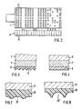
- the layer 28 is expediently applied as a porous layer by plasma spraying. After it has been applied by chipless shaping with a cup 29, cf. Fig. 7 provided. This ensures at the same time that the outside of the layer 28 passes through closed.
- the wells are introduced in a state defining the first shape Temperature T 4. Then the temperature of the layer 28 is brought to the value T 2, at which it assumes the second shape. Then the cup 29 'of the second shape is given the desired final shape. This can again be done, for example, by mettling.
- the inner porosity of the layer 28 in the first shape state is necessary in order to prevent a change in the outer diameter upon transition to the second shape state.
- the cylinder 30 is rotatably mounted on a fixed axis 31 and in turn has a porous layer 33 made of a material with a temperature-dependent shape memory that is applied to a metallic core 32. Cups 34 are introduced into the layer 33.
- the cylinder 30 has an inner cavity 35 which is connected to a water circuit 38 via bores 36, 37.
- a heat exchanger 39 in which the water flowing through can be cooled.
- a feed pump 40 is also provided in the water circuit 38.
- a second heat exchanger can also be provided to increase the temperature of the water cycle.
- the layer 33 is guided from one to the other by heating the circulating water of the water circuit 38.
- the water of the water cycle can be cooled or the temperature for reaching the first shape is such that it is reached automatically after the printing machine is switched off.
- a porous layer 51 made of a material with a temperature-dependent shape memory is applied to a hard core 50 of a cylinder, as is the case with the arrangement according to FIGS. 7 and 8. Cups are provided in layer 51, which are in the first shape 53 and are designated in the second form with 53 '.
- a wear protection layer 52 is applied to the outside of the layer 51.
- the wear protection layer 52 is only a few ⁇ m thick and suitably consists of TiN, TiAlN or TiCN.
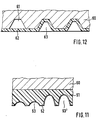
- FIG. 12 A further variant is shown in FIG. 12.
- depressions 61 are machined into the outer surface of a hard core 60 of a cylinder.
- the layer 62 made of a material with a temperature-dependent shape memory is designed as a thin-walled sleeve applied to the core.
- the layer 62 thus forms part of a cylinder jacket.
- wells 63 are formed in the area of the depressions 61.
- the depressions 61 are dimensioned such that they accommodate the layer 62 forming the wells 63.
- This configuration is not only suitable for anilox rollers but also for gravure cylinders. Basically, in this variant there is also the possibility that the layer 62 forms flatter cells in the first shape, as is the case with the arrangement according to FIGS. 7 and 8. Then it can be used for anilox rollers.
Landscapes
- Inking, Control Or Cleaning Of Printing Machines (AREA)
- Printing Methods (AREA)
- Manufacture Or Reproduction Of Printing Formes (AREA)
- Printing Plates And Materials Therefor (AREA)
Abstract
Description
- Die Erfindung betrifft ein Druckwerk für eine Druckmaschine mit einem mit Näpfchen versehenen, mit einer Rakel zusammenwirkenden, farbführenden Zylinder.
- Der Erfindung liegt die Aufgabe zugrunde ein Druckwerk so auszubilden, daß die Menge der vom Zylinder geführten Farbe verschleißfrei verändert werden kann.
- Erfindungsgemäß wird dies durch Anwendung der Merkmale des Kennzeichens des Anspruchs 1 erreicht.
- Bei Anwendung der Erfindung ergibt sich der zusätzliche Vorteil, daß auch die Verteilung der Farbe entlang des Umfangs des Zylinders verändert werden kann.
- Mehrere Ausführungsbeispiele der Erfindung sind anhand der Zeichnung beschrieben. Auf dieser zeigt
- Fig. 1 ein Tiefdruckwerk in einer schematischen Seitenansicht,
- Fig. 2 eine schematische Ansicht des Tiefdruckformzylinders nach Fig. 1 von oben,
- Fig. 3 einen Ausschnitt aus dem Zylinder nach Fig. 2 in einem ersten Formzustand,
- Fig. 4 den Ausschnitt nach Fig. 3 in einem zweiten Formzustand
- Fig. 5 ein Diagramm,
- Fig. 6 eine schematische Darstellung eines Offsetdruckwerkes in einer Seitenansicht,
- Fig. 7 einen Ausschnitt aus der Rasterwalze nach Fig. 6 in vergrößertem Maßstab in einem ersten Formzustand,
- Fig. 8 einen Fig. 7 entsprechenden Ausschnitt in einem zweiten Formzustand,
- Fig. 9 eine Rasterwalze in einem Querschnitt,
- Fig. 10 einen Längsschnitt durch die Rasterwalze gemäß Fig. 9 und
- Fig. 11 und 12 jeweils zwei Ausschnitte weiterer Ausführungsformen von Zylindern.
- Das Druckwerk gemäß Fig. 1 weist einen Tiefdruckformzylinder 1 und einen Gegendruckzylinder 2 auf, zwischen denen die zu bedruckende Bahn 3 hindurchgeführt ist. Der Tiefdruckformzylinder 1 taucht partiell in eine Farbwanne 4 ein. An den Tiefdruckformzylinder 1 ist eine Rakel 5 anstellbar.
- Der Tiefdruckformzylinder 1 weist, vgl. Fig. 3 und 4 einen metallischen Kern 6 auf, auf den eine poröse, volumenveränderbare Zwischenschicht 7, beispielsweise durch Plasmasprühen aufgetragen ist. Auf die Zwischenschicht 6 ist außen eine Schicht 8 aus einem Werkstoff mit einem temperaturabhängigen Formgedächtnis aufgebracht. Werkstoffe mit einem temperaturabhängigen Formgedächtnis können auf metallischer Basis aufgebaut sein, wie sie beispielsweise in der Zeitschrift "Maschinenmarkt" 1987, Seiten 58 bis 61 und 70 bis 73 beschrieben sind oder auf Kunststoffbasis aufgebaut sein, wie sie in der Zeitschrift "highTech" Heft 4/1989 beschrieben sind.
- Vor dem Umfang des Tiefdruckformzylinders 1 ist eine Temperiereinrichtung 9 vorgesehen. Die Temperiereinrichtung 9 weist, wie in Fig. 2 schematisch gezeigt, eine Vielzahl von nebeneinander angeordneten Heizelementen 10 in Form sehr kleiner Widerstände auf. Der Aufbau derartiger Wärmequellen ist in der Zeitschrift "Feinwerktechnik und Meßtechnik" 95(1987)7 Seiten 433 bis 435 beschrieben.
- Fig. 3 zeigt, daß in die Schicht 8 eine Vielzahl von Näpfchen 11 eingebracht ist. Dies kann beispielsweise durch Molettieren, also eine spanlose Verformung des Tiefdruckformzylinders 1 erfolgen. Fig. 3 gibt die Form der Schicht 8 in einem ersten Formzustand wieder. Jeder in Umfangsrichtung umlaufenden Reihe von Näpfchen 11 ist in der Temperiereinrichtung 9 ein Heizelement 10 zugeordnet, wie in Fig. 2 schematisch dargestellt ist. Wird ein Heizelement 10 eingeschaltet, so erwärmt es den Bereich eines Näpfchens 11 der Schicht 8. Die Schicht 8 verformt sich infolgedessen in diesem Bereich und nimmt den in Fig. 4 wiedergegebenen zweiten Formzustand ein, in der das jeweilige Näpfchen 11 verschwindet und die Schicht 8 im Bereich des Näpfchens einen Abschnitt eines Zylindermantels bildet. Dabei stellt die poröse Zwischenschicht 7 sicher, daß sich der Außendurchmesser des Tiefdruckformzylinders 1 beim übergang von dem einen in den anderen Formzustand nicht ändert. Durch schrittweises Drehen des Tiefdruckformzylinders 1 können somit nacheinander einige oder alle Näpfchen 11 einer Näpfchenreihe von einem Heizelement 10 mit Wärme beaufschlagt werden. Fig. 2 zeigt, daß es mit dieser Anordnung sowohl möglich ist, eine gesamte in Umfangsrichtung umlaufende Näpfchenreihe zu löschen als auch in Umfangsrichtung abwechselnd Näpfchen 11 offen zu lassen und benachbarte Näpfchen zu löschen. Hierdurch kann somit eine dem zu druckenden Sujet angepaßte Näpfchenkonfiguration in der Schicht 8 des Tiefdruckformzylinders 1 erzeugt werden.
- Im Diagramm nach Fig. 5 ist die Anderung des Formzustandes eines Werkstoffs mit temperaturabhängigem Formgedächtnis über der Temperatur aufgetragen. Der Linienzug a zeigt, daß der erste Formzustand F 1 bis zum Erreichen einer Temperatur T 1 erhalten bleibt. Bei einer höheren Temperatur T 2 ist dann der zweite Formzustand F 2 erreicht. Wie der Linienzug b zeigt, bleibt der zweite Formzustand F 2 bis zum Erreichen einer Temperatur T 3, die unter den Temperaturen T 1 und T 2 liegt, erhalten. Erst bei weiterer Abkühlung auf die Temperatur T 4 wird der erste Formzustand F 1 wieder erreicht. Zwischen den Temperaturen T 1 und T 3, also im Abschnitt ΔT, bleibt somit der jeweils gegebene Formzustand unverändert beibehalten. Liegt der Bereich der üblichen ArbeitstemperaturenΔT* der Druckmaschine innerhalb des Bereichs ΔT,so bleibt der Formzustand im Bereich jedes einzelnen Näpfchens während des Betriebs der Druckmaschine unverändert.
- Beim Druckwerk gemäß Fig. 6 sind ein Gummituchzylinder 20, ein mit einer Offsetdruckplatte belegbarer Plattenzylinder 21, eine Auftragwalze 22 mit nachgiebiger farbannehmender Oberfläche und ein als Rasterwalze dienender Zylinder 23 vorgesehen. An den Plattenzylinder 21 ist ein Feuchtwerk 24 anstellbar. Die Rasterwalze 23 wird von einer Kammerrakel 25 mit Farbe versorgt. An einer freien Stelle des Umfangs des Zylinders 23 ist weiterhin eine Temperiereinrichtung 26 angeordnet. Die Temperiereinrichtung 26 besteht aus einem über die ganze Breite des Zylinders 23 durchlaufenden Widerstandsheizstab. Falls gewünscht, kann der Heizstab auch in zonenbreite einzeln ein- und ausschaltbare Abschnitte unterteilt sein. Grundsätzlich besteht hier auch die Möglichkeit, eine Temperiereinrichtung entsprechend Fig. 1 zu verwenden. Eine damit gegebene Ansteuerung einzelner Näpfchen ist aber bei Rasterwalzen nicht immer erforderlich.
- Der Zylinder 23 weist, wie die Fig. 7 und 8 zeigen, einen harten metallischen Kern 27 auf, auf den eine Schicht 28 aus einem Werkstoff mit einem temperaturabhängigen Formgedächtnis aufgebracht ist. Die Schicht 28 ist als poröse Schicht zweckmäßig durch Plasmasprühen aufgebracht. Sie wird nach ihrem Aufbringen durch spanlose Verformung mit Näpfchen 29, vgl. Fig. 7, versehen. Hierdurch wird gleichzeitig sichergestellt, daß die Außenseite der Schicht 28 geschlossen durchläuft. Das Einbringen der Näpfchen erfolgt dabei bei einer den ersten Formzustand definierenden Temperatur T 4. Anschließend wird die Temperatur der Schicht 28 auf den Wert T 2 gebracht, bei der sie den zweiten Formzustand annimmt. Hierauf wird den Näpfchen 29′ des zweiten Formzustandes die gewünschte endgültige Form gegeben. Dies kann wiederum beispielsweise durch Molettieren erfolgen. Die innere Porosität der Schicht 28 im ersten Formzustand ist hierbei erforderlich, um eine Veränderung des Außendurchmessers bei Obergang zum zweiten Formzustand zu verhindern.
- Zum Abkühlen und zur Rückführung auf den Ausgangszustand besteht weiterhin die Möglichkeit, als Rasterwalze einen Zylinder 30 gemäß Fig. 9 und 10 zu verwenden. Der Zylinder 30 ist drehbar auf einer festen Achse 31 gelagert und weist wiederum eine auf einen metallischen Kern 32 aufgebrachte poröse Schicht 33 aus einem Werkstoff mit temperaturabhängigen Formgedächtnis auf. In die Schicht 33 sind Näpfchen 34 eingebracht. Der Zylinder 30 weist einen Innenhohlraum 35 auf, der über Bohrungen 36, 37 an einen Wasserkreislauf 38 angeschlossen ist. Im Wasserkreislauf 38 befindet sich ein Wärmetauscher 39, in dem das durchfließende Wasser abkühlt werden kann. Zur Aufrechterhaltung des Durchflusses ist im Wasserkreislauf 38 weiterhin eine Förderpumpe 40 vorgesehen. Falls erforderlich, kann neben diesem Wärmetauscher 39 noch ein zweiter Wärmetauscher zur Erhöhung der Temperatur des Wasserkreislaufes vorgesehen sein. Bei letzterer Ausführung wird eine Oberführung der Schicht 33 vom einen in den anderen Formzustand durch Erwärmen des umlaufenden Wassers des Wasserkreislaufes 38 bewirkt. Zur Rückführung in den ersten Formzustand kann dann entweder das Wasser des Wasserkreislaufes gekühlt werden oder die Temperatur zum Erreichen des ersten Formzustandes liegt so, daß sie automatisch nach dem Abstellen der Druckmaschine erreicht wird.
- Fig. 11 zeigt eine weitere Beschichtung. Hier ist auf einen harten Kern 50 eines Zylinders eine poröse Schicht 51 aus einem Werkstoff mit einem temperaturabhängigen Formgedächtnis aufgebracht, sowie dies bei der Anordnung nach Fig. 7 und 8 der Fall ist. In der Schicht 51 sind Näpfchen vorgesehen, die im ersten Formzustand mit 53 und im zweiten Formzustand mit 53′ bezeichnet sind. Zusätzlich ist außen auf die Schicht 51 eine Verschleißschutzschicht 52 aufgebracht. Die Verschleißschutzschicht 52 ist nur wenige µ dick und besteht zweckmäßig aus TiN, TiAlN oder TiCN.
- Eine weitere Variante zeigt Fig. 12. Bei dieser Anordnung sind in die Außenfläche eines harten Kernes 60 eines Zylinders Vertiefungen 61 eingearbeitet. Die Schicht 62 aus einem Werkstoff mit temperaturabhängigem Formgedächtnis ist als dünnwandige, auf den Kern aufgebrachte Hülse ausgebildet. In dem ersten in Fig. 12 links dargestellten Formzustand bildet somit die Schicht 62 einen Teil eines Zylindermantels. Nach Oberführung der Schicht 62 in den zweiten Formzustand durch Erwärmung bilden sich im Bereich der Vertiefungen 61 Näpfchen 63. Dabei sind die Vertiefungen 61 so bemessen, daß sie die Näpfchen 63 bildende Schicht 62 aufnehmen. Diese Ausgestaltung ist nicht nur für Rasterwalzen sondern auch für Tiefdruckformzylinder geeignet. Grundsätzlich besteht bei dieser Variante auch die Möglichkeit, daß die Schicht 62 bereits im ersten Formzustand flachere Näpfchen bildet, sowie dies bei der Anordnung gemäß Fig. 7 und 8 der Fall ist. Dann ist sie für Rasterwalzen verwendbar.
Claims (10)
Applications Claiming Priority (2)
| Application Number | Priority Date | Filing Date | Title |
|---|---|---|---|
| DE3938449 | 1989-11-18 | ||
| DE3938449A DE3938449A1 (de) | 1989-11-18 | 1989-11-18 | Druckwerk |
Publications (3)
| Publication Number | Publication Date |
|---|---|
| EP0428893A2 true EP0428893A2 (de) | 1991-05-29 |
| EP0428893A3 EP0428893A3 (en) | 1991-12-11 |
| EP0428893B1 EP0428893B1 (de) | 1995-10-04 |
Family
ID=6393838
Family Applications (1)
| Application Number | Title | Priority Date | Filing Date |
|---|---|---|---|
| EP90120395A Expired - Lifetime EP0428893B1 (de) | 1989-11-18 | 1990-10-24 | Druckwerk |
Country Status (4)
| Country | Link |
|---|---|
| US (1) | US5233921A (de) |
| EP (1) | EP0428893B1 (de) |
| JP (1) | JPH03176154A (de) |
| DE (2) | DE3938449A1 (de) |
Cited By (5)
| Publication number | Priority date | Publication date | Assignee | Title |
|---|---|---|---|---|
| EP0703093A1 (de) * | 1994-09-24 | 1996-03-27 | MAN Roland Druckmaschinen AG | Walze, vorzugsweise für ein Feuchtwerk einer Druckmaschine |
| WO2008110434A3 (de) * | 2007-03-09 | 2008-11-06 | Oce Printing Systems Gmbh | Vorrichtung zum auftragen eines fluids auf einen bedruckstoff |
| EP2384888A3 (de) * | 2010-05-05 | 2012-02-08 | Giesecke & Devrient GmbH | Flexodruckwerk, Flexodruckwerkverfahren und daraus erhältliches Druckerzeugnis |
| ITVR20100171A1 (it) * | 2010-09-08 | 2012-03-09 | Uteco Converting Spa | Struttura di cilindro retinato particolarmente per macchine da stampa flessografiche |
| EP2581227A1 (de) * | 2011-10-14 | 2013-04-17 | Bobst Bielefeld GmbH | Farbwalze und Farbwalzensatz für Farbproofing |
Families Citing this family (34)
| Publication number | Priority date | Publication date | Assignee | Title |
|---|---|---|---|---|
| DE4137337A1 (de) * | 1991-11-13 | 1993-05-19 | Sengewald Karl H Gmbh | Hochdruckverfahren und auftragsvorrichtung zu seiner durchfuehrung |
| DE4206525C2 (de) * | 1992-03-02 | 2001-05-17 | Heidelberger Druckmasch Ag | Vorrichtung zur Beeinflussung einer Feuchtmittelverteilung in einem Druckwerk einer Druckmaschine |
| DE4408615C2 (de) * | 1994-03-15 | 1996-01-11 | Roland Man Druckmasch | Näpfchenwalze innerhalb eines Auftragswerks einer Rotationsdruckmaschine |
| US5524342A (en) * | 1994-05-27 | 1996-06-11 | Xerox Corporation | Methods for shrinking nickel articles |
| DE19645934A1 (de) * | 1996-11-07 | 1998-05-14 | Roland Man Druckmasch | Rasterwalze innerhalb eines Auftragswerkes einer Rotationsdruckmaschine |
| DE19653911C2 (de) * | 1996-12-21 | 2003-03-27 | Roland Man Druckmasch | Druckmaschinenwalze mit einer farbfreundlichen Beschichtung der Ballenfläche des Walzenkerns, insbesondere Farbwalze |
| US6006665A (en) * | 1997-10-30 | 1999-12-28 | Didde Web Press Corporation | Pliable anilox roller |
| US6024907A (en) * | 1998-02-02 | 2000-02-15 | Bruce Jagunich | Embossing with an endless belt composed of a shape memory alloy |
| US6092465A (en) * | 1998-03-03 | 2000-07-25 | United Container Machinery, Inc. | Method and apparatus for providing erasable relief images |
| DE19901243A1 (de) * | 1999-01-14 | 2000-07-20 | Heidelberger Druckmasch Ag | Dosierbare Rasterwalze in einer Rotationsdruckmaschine |
| DE19925420A1 (de) * | 1999-06-02 | 2000-12-07 | Voith Sulzer Papiertech Patent | Elastische Walze und Verfahren zum Herstellen einer solchen |
| DE10001364C2 (de) * | 2000-01-14 | 2002-08-14 | Windmoeller & Hoelscher | Auftragswalze zum Übertragen eines formatgerechten Klebstoffauftrags |
| DE10021451A1 (de) * | 2000-05-03 | 2001-11-08 | Heidelberger Druckmasch Ag | Gesteuerte Bebilderung und Löschung einer Druckform aus metallischem Titan |
| DE10145403A1 (de) * | 2001-07-04 | 2003-01-16 | Any Seyd Ahmadiyan | Vorrichtung zur zonalen Farbdosierung und Aktuator mit einem Aktuatordraht aus einer Formgedächtnislegierung |
| US6779444B2 (en) | 2001-08-01 | 2004-08-24 | Heidelberger Druckmaschinen Ag | Printing form and process for producing the printing form |
| DE10213012B4 (de) * | 2001-08-01 | 2011-08-11 | Heidelberger Druckmaschinen AG, 69115 | Verfahren zur Herstellung einer Druckform |
| US6663215B2 (en) * | 2001-10-25 | 2003-12-16 | Hewlett-Packard Company, L.P. | Printhead service station |
| EP1415805A1 (de) * | 2002-10-28 | 2004-05-06 | Hauni Maschinenbau AG | Druckwerk mit Temperiereinrichtung |
| SI1493552T1 (sl) * | 2003-07-01 | 2006-08-31 | Delicarta Spa | Naprava in postopek za vtiskovanje listnatega materiala |
| DE102005030918A1 (de) * | 2005-06-30 | 2007-01-04 | Man Roland Druckmaschinen Ag | Farbduktorwalze einer Rollendruckmaschine |
| CN1939721B (zh) * | 2005-09-27 | 2010-12-15 | 海德堡印刷机械股份公司 | 用于对印刷机调节温度的方法 |
| DE102006040746B4 (de) * | 2005-09-27 | 2017-04-27 | Heidelberger Druckmaschinen Ag | Verfahren zum Temperieren einer Druckmaschine |
| US7762188B2 (en) * | 2005-09-30 | 2010-07-27 | Xerox Corporation | Reimageable printing member |
| US7814830B2 (en) * | 2005-11-07 | 2010-10-19 | Xerox Corporation | Printing system using shape-changing materials |
| DE102006031682A1 (de) * | 2006-07-08 | 2008-01-10 | Man Roland Druckmaschinen Ag | Flexodruckrasterwalze und Flexodruckverfahren |
| DE102007041203A1 (de) | 2006-10-11 | 2008-04-24 | Man Roland Druckmaschinen Ag | Kurzfarbwerk für eine Verarbeitungsmaschine |
| US20080240794A1 (en) * | 2007-03-26 | 2008-10-02 | Research Laboratories Of Australia Pty Ltd | Printing machine incorporating plastic metering roller |
| DE102008011241B4 (de) | 2008-02-26 | 2015-06-11 | manroland sheetfed GmbH | Verarbeitungsmaschine mit einem Kurzfarbwerk |
| DE102008028675A1 (de) * | 2008-06-17 | 2009-12-24 | Wifag Maschinenfabrik Ag | Elektro- oder magnetorheologische Druckmaschine |
| DE102009007343A1 (de) * | 2009-02-04 | 2010-08-05 | OCé PRINTING SYSTEMS GMBH | Anordnung zum Transport eines flüssigen Farbmediums bei einem Druckgerät |
| DE102014001970A1 (de) * | 2014-02-13 | 2015-08-13 | Heidelberger Druckmaschinen Ag | Baugruppe einer bogen- oder bahnförmigen Bedruckstoff verarbeitenden Maschine |
| ES2701477T3 (es) * | 2014-11-05 | 2019-02-22 | Bobst Mex Sa | Procedimientos de realización de una herramienta de estampado hembra, herramientas de estampado, módulo y procedimiento de estampado y máquina de estampado equipada con dichas herramientas |
| CN104698688B (zh) * | 2015-04-03 | 2017-08-01 | 合肥京东方光电科技有限公司 | 摩擦辊及其使用方法 |
| CN105807500B (zh) * | 2016-05-31 | 2019-03-12 | 京东方科技集团股份有限公司 | 转印装置和转印方法 |
Family Cites Families (8)
| Publication number | Priority date | Publication date | Assignee | Title |
|---|---|---|---|---|
| US3382798A (en) * | 1965-10-21 | 1968-05-14 | Homer L. Bishop | Method of shaping the image bearing surface of printing plates |
| US3654864A (en) * | 1970-01-16 | 1972-04-11 | Energy Conversion Devices Inc | Printing employing materials with variable volume |
| US4793041A (en) * | 1979-05-03 | 1988-12-27 | Jerome D. Jenkins | Transfer roll with ceramic-fluorocarbon coating containing cylindrical ink holes with round, beveled entrances |
| DE3167878D1 (en) * | 1980-12-04 | 1985-01-31 | Dainippon Printing Co Ltd | Sleeve-type gravure printing cylinder and method and apparatus for its assembly |
| DE3046757C2 (de) * | 1980-12-12 | 1985-09-12 | W.C. Heraeus Gmbh, 6450 Hanau | Tiefdruckzylinder |
| US4603634A (en) * | 1985-02-04 | 1986-08-05 | Rockwell International Corporation | Copper and nickel layered ink metering roller |
| DE3706011A1 (de) * | 1987-02-25 | 1988-09-08 | Roland Man Druckmasch | Kurzfarbwerk |
| DE3832160A1 (de) * | 1988-09-22 | 1990-04-12 | Roland Man Druckmasch | Rakelfarbwerk |
-
1989
- 1989-11-18 DE DE3938449A patent/DE3938449A1/de active Granted
-
1990
- 1990-10-24 EP EP90120395A patent/EP0428893B1/de not_active Expired - Lifetime
- 1990-10-24 DE DE59009741T patent/DE59009741D1/de not_active Expired - Fee Related
- 1990-11-01 US US07/607,533 patent/US5233921A/en not_active Expired - Fee Related
- 1990-11-15 JP JP2307353A patent/JPH03176154A/ja active Pending
Cited By (9)
| Publication number | Priority date | Publication date | Assignee | Title |
|---|---|---|---|---|
| EP0703093A1 (de) * | 1994-09-24 | 1996-03-27 | MAN Roland Druckmaschinen AG | Walze, vorzugsweise für ein Feuchtwerk einer Druckmaschine |
| WO2008110434A3 (de) * | 2007-03-09 | 2008-11-06 | Oce Printing Systems Gmbh | Vorrichtung zum auftragen eines fluids auf einen bedruckstoff |
| EP2384888A3 (de) * | 2010-05-05 | 2012-02-08 | Giesecke & Devrient GmbH | Flexodruckwerk, Flexodruckwerkverfahren und daraus erhältliches Druckerzeugnis |
| ITVR20100171A1 (it) * | 2010-09-08 | 2012-03-09 | Uteco Converting Spa | Struttura di cilindro retinato particolarmente per macchine da stampa flessografiche |
| EP2428361A1 (de) * | 2010-09-08 | 2012-03-14 | Uteco Converting S.p.A. | Aniloxwalze, insbesondere für Flexodruckmaschinen |
| AU2011218777B2 (en) * | 2010-09-08 | 2014-04-24 | Uteco Converting S.P.A. | Anilox roller, particularly for flexographic printing machines |
| RU2572583C2 (ru) * | 2010-09-08 | 2016-01-20 | Утеко Конвертинг С.П.А. | Анилоксовый валик, в частности, для флексографских печатных машин |
| US9555619B2 (en) | 2010-09-08 | 2017-01-31 | Uteco Converting S.P.A. | Anilox roller, particularly for flexographic printing machines |
| EP2581227A1 (de) * | 2011-10-14 | 2013-04-17 | Bobst Bielefeld GmbH | Farbwalze und Farbwalzensatz für Farbproofing |
Also Published As
| Publication number | Publication date |
|---|---|
| US5233921A (en) | 1993-08-10 |
| DE3938449A1 (de) | 1991-05-23 |
| DE3938449C2 (de) | 1993-02-11 |
| DE59009741D1 (de) | 1995-11-09 |
| JPH03176154A (ja) | 1991-07-31 |
| EP0428893A3 (en) | 1991-12-11 |
| EP0428893B1 (de) | 1995-10-04 |
Similar Documents
| Publication | Publication Date | Title |
|---|---|---|
| DE3938449C2 (de) | ||
| EP0225509B2 (de) | Vorrichtung zum Bedrucken einer Bahn | |
| DE10160734B4 (de) | Druckmaschine | |
| DE3541458C2 (de) | ||
| EP0110092B1 (de) | Kühlwalze | |
| DE3726820A1 (de) | Thermoregler fuer einen druckformzylinder in einer offset-presse | |
| DE4431188C2 (de) | Druckwerk für wasserlosen Offsetdruck | |
| DE4426077A1 (de) | Druckmaschinen-Temperierungsvorrichtung | |
| DE10360108A1 (de) | Herstellung einer wiederverwendbaren Druckform | |
| EP2242651A2 (de) | Rotationsflachdruckmaschine mit einer mit einer porösen oberfläche versehenen feuchtwerkswalze | |
| DE3134796C2 (de) | Farbwerk für eine Rotationsdruckmaschine | |
| EP1457331B1 (de) | Kurzfarbwerk einer Rotationsdruckmaschine | |
| DE2259085A1 (de) | Farbwerk fuer flachdruckmaschinen | |
| DE4401362C2 (de) | Verfahren und Rotationsdruckmaschine für indirekten Tiefdruck | |
| EP0518892B1 (de) | Kurzfarbwerk für eine rollenrotationsdruckmaschine | |
| DE19937467A1 (de) | Vorrichtung zum Temperieren von Beschichtungsmedien | |
| EP1250227B1 (de) | Farbauftrageinrichtung | |
| DE19527889C2 (de) | Kurzfarbwerk zum Einfärben einer Flachdruckplatte | |
| DE9408328U1 (de) | Formzylinder | |
| DE3102043A1 (de) | "anordnung zur dosierung des feuchtmittels fuer offset-druckmaschinen" | |
| CH655055A5 (de) | Sammeldruck-rotationsmaschinendruckwerk fuer wertpapierdruck. | |
| DE102009005083A1 (de) | Rotationsflachdruckmaschine | |
| WO2001017778A1 (de) | Farbwalze und verfahren zum auftragen von farbe | |
| DE10325185B4 (de) | Verfahren zum Betrieb eines Druckwerks einer Druckmaschine in Abhängigkeit von der Farbtemperatur sowie nach dem Verfahren arbeitende Druckmaschinensteuerung | |
| DE4101797A1 (de) | Kurzfarbwerk fuer eine rollenrotationsdruckmaschine |
Legal Events
| Date | Code | Title | Description |
|---|---|---|---|
| PUAI | Public reference made under article 153(3) epc to a published international application that has entered the european phase |
Free format text: ORIGINAL CODE: 0009012 |
|
| AK | Designated contracting states |
Kind code of ref document: A2 Designated state(s): CH DE FR GB IT LI |
|
| PUAL | Search report despatched |
Free format text: ORIGINAL CODE: 0009013 |
|
| AK | Designated contracting states |
Kind code of ref document: A3 Designated state(s): CH DE FR GB IT LI |
|
| 17P | Request for examination filed |
Effective date: 19920124 |
|
| 17Q | First examination report despatched |
Effective date: 19930812 |
|
| ITF | It: translation for a ep patent filed | ||
| GRAA | (expected) grant |
Free format text: ORIGINAL CODE: 0009210 |
|
| AK | Designated contracting states |
Kind code of ref document: B1 Designated state(s): CH DE FR GB IT LI |
|
| REF | Corresponds to: |
Ref document number: 59009741 Country of ref document: DE Date of ref document: 19951109 |
|
| GBT | Gb: translation of ep patent filed (gb section 77(6)(a)/1977) |
Effective date: 19960108 |
|
| ET | Fr: translation filed | ||
| PLBE | No opposition filed within time limit |
Free format text: ORIGINAL CODE: 0009261 |
|
| STAA | Information on the status of an ep patent application or granted ep patent |
Free format text: STATUS: NO OPPOSITION FILED WITHIN TIME LIMIT |
|
| 26N | No opposition filed | ||
| PGFP | Annual fee paid to national office [announced via postgrant information from national office to epo] |
Ref country code: GB Payment date: 19980914 Year of fee payment: 9 |
|
| PGFP | Annual fee paid to national office [announced via postgrant information from national office to epo] |
Ref country code: FR Payment date: 19980916 Year of fee payment: 9 |
|
| PGFP | Annual fee paid to national office [announced via postgrant information from national office to epo] |
Ref country code: DE Payment date: 19980922 Year of fee payment: 9 |
|
| PGFP | Annual fee paid to national office [announced via postgrant information from national office to epo] |
Ref country code: CH Payment date: 19980929 Year of fee payment: 9 |
|
| PG25 | Lapsed in a contracting state [announced via postgrant information from national office to epo] |
Ref country code: GB Free format text: LAPSE BECAUSE OF NON-PAYMENT OF DUE FEES Effective date: 19991024 |
|
| PG25 | Lapsed in a contracting state [announced via postgrant information from national office to epo] |
Ref country code: LI Free format text: LAPSE BECAUSE OF NON-PAYMENT OF DUE FEES Effective date: 19991031 Ref country code: CH Free format text: LAPSE BECAUSE OF NON-PAYMENT OF DUE FEES Effective date: 19991031 |
|
| GBPC | Gb: european patent ceased through non-payment of renewal fee |
Effective date: 19991024 |
|
| REG | Reference to a national code |
Ref country code: CH Ref legal event code: PL |
|
| PG25 | Lapsed in a contracting state [announced via postgrant information from national office to epo] |
Ref country code: FR Free format text: LAPSE BECAUSE OF NON-PAYMENT OF DUE FEES Effective date: 20000630 |
|
| PG25 | Lapsed in a contracting state [announced via postgrant information from national office to epo] |
Ref country code: DE Free format text: LAPSE BECAUSE OF NON-PAYMENT OF DUE FEES Effective date: 20000801 |
|
| REG | Reference to a national code |
Ref country code: FR Ref legal event code: ST |
|
| PG25 | Lapsed in a contracting state [announced via postgrant information from national office to epo] |
Ref country code: IT Free format text: LAPSE BECAUSE OF NON-PAYMENT OF DUE FEES;WARNING: LAPSES OF ITALIAN PATENTS WITH EFFECTIVE DATE BEFORE 2007 MAY HAVE OCCURRED AT ANY TIME BEFORE 2007. THE CORRECT EFFECTIVE DATE MAY BE DIFFERENT FROM THE ONE RECORDED. Effective date: 20051024 |