EP0428974A2 - Apparat und Verfahren zur Durchführung einer durch einen Fühler gesteuerten Bearbeitung, z.B. Aufrauhen an der Kante eines Schuhoberteils - Google Patents
Apparat und Verfahren zur Durchführung einer durch einen Fühler gesteuerten Bearbeitung, z.B. Aufrauhen an der Kante eines Schuhoberteils Download PDFInfo
- Publication number
- EP0428974A2 EP0428974A2 EP90121611A EP90121611A EP0428974A2 EP 0428974 A2 EP0428974 A2 EP 0428974A2 EP 90121611 A EP90121611 A EP 90121611A EP 90121611 A EP90121611 A EP 90121611A EP 0428974 A2 EP0428974 A2 EP 0428974A2
- Authority
- EP
- European Patent Office
- Prior art keywords
- tracer
- supported
- edge
- frame
- brush
- Prior art date
- Legal status (The legal status is an assumption and is not a legal conclusion. Google has not performed a legal analysis and makes no representation as to the accuracy of the status listed.)
- Withdrawn
Links
Images


Classifications
-
- B—PERFORMING OPERATIONS; TRANSPORTING
- B23—MACHINE TOOLS; METAL-WORKING NOT OTHERWISE PROVIDED FOR
- B23Q—DETAILS, COMPONENTS, OR ACCESSORIES FOR MACHINE TOOLS, e.g. ARRANGEMENTS FOR COPYING OR CONTROLLING; MACHINE TOOLS IN GENERAL CHARACTERISED BY THE CONSTRUCTION OF PARTICULAR DETAILS OR COMPONENTS; COMBINATIONS OR ASSOCIATIONS OF METAL-WORKING MACHINES, NOT DIRECTED TO A PARTICULAR RESULT
- B23Q35/00—Control systems or devices for copying directly from a pattern or a master model; Devices for use in copying manually
- B23Q35/04—Control systems or devices for copying directly from a pattern or a master model; Devices for use in copying manually using a feeler or the like travelling along the outline of the pattern, model or drawing; Feelers, patterns, or models therefor
- B23Q35/42—Patterns; Masters models
- B23Q35/46—Supporting devices therefor
-
- A—HUMAN NECESSITIES
- A43—FOOTWEAR
- A43D—MACHINES, TOOLS, EQUIPMENT OR METHODS FOR MANUFACTURING OR REPAIRING FOOTWEAR
- A43D119/00—Driving or controlling mechanisms of shoe machines; Frames for shoe machines
-
- A—HUMAN NECESSITIES
- A43—FOOTWEAR
- A43D—MACHINES, TOOLS, EQUIPMENT OR METHODS FOR MANUFACTURING OR REPAIRING FOOTWEAR
- A43D37/00—Machines for roughening soles or other shoe parts preparatory to gluing
-
- B—PERFORMING OPERATIONS; TRANSPORTING
- B23—MACHINE TOOLS; METAL-WORKING NOT OTHERWISE PROVIDED FOR
- B23Q—DETAILS, COMPONENTS, OR ACCESSORIES FOR MACHINE TOOLS, e.g. ARRANGEMENTS FOR COPYING OR CONTROLLING; MACHINE TOOLS IN GENERAL CHARACTERISED BY THE CONSTRUCTION OF PARTICULAR DETAILS OR COMPONENTS; COMBINATIONS OR ASSOCIATIONS OF METAL-WORKING MACHINES, NOT DIRECTED TO A PARTICULAR RESULT
- B23Q1/00—Members which are comprised in the general build-up of a form of machine, particularly relatively large fixed members
- B23Q1/25—Movable or adjustable work or tool supports
- B23Q1/44—Movable or adjustable work or tool supports using particular mechanisms
- B23Q1/50—Movable or adjustable work or tool supports using particular mechanisms with rotating pairs only, the rotating pairs being the first two elements of the mechanism
- B23Q1/54—Movable or adjustable work or tool supports using particular mechanisms with rotating pairs only, the rotating pairs being the first two elements of the mechanism two rotating pairs only
- B23Q1/5406—Movable or adjustable work or tool supports using particular mechanisms with rotating pairs only, the rotating pairs being the first two elements of the mechanism two rotating pairs only a single rotating pair followed perpendicularly by a single rotating pair
- B23Q1/5412—Movable or adjustable work or tool supports using particular mechanisms with rotating pairs only, the rotating pairs being the first two elements of the mechanism two rotating pairs only a single rotating pair followed perpendicularly by a single rotating pair followed perpendicularly by a single rotating pair
Definitions
- the present invention relates to the field of footwear machines and working, and particularly but not exclusively to a roughing operation, such as is generally carried out on the edge of an upper to make it rougher and to aid the application of an adhesive and the adhesion of a sole.
- Roughing is generally carried out on the edge of an upper previously folded onto an insole of the footwear, the insole and the upper being supported by a last (figure 1); it can be carried out by means of an abrasive cloth or a metal brush and it can be performed by hand or by machine.
- Machines for roughing at present on the market are usually programmable electronic machines, on which the movement of the brushes is programmed previous to beginning work on a series of footwear.
- the aim of this invention is to avoid the drawbacks of the previous technique.
- the apparatus comprises a tracer suitable for being placed in contact with the edge to be roughed, a rotating roughing wheel or brush, whose shaft is supported by an oscillating arm, with means interposed between the tracer and the brush supporting arm to adjust at least partially the position of the latter on the basis of the shifting of the former determined by the detected shape.
- the brush supporting arm is supported integrally with a body which is pivotable around a horizontal axis and this horizontal axis is supported on a frame which is rotatable around a vertical axis.
- the rotation of the frame around the vertical axis and therefore 25. the angular or horizontal shifting of the brush is determined from the tracer which is pressed on the same profile to be worked, through a potentiometer, an electromechanical transducer, in particular an electropneumatic one, and an actuator unit, for example a cylinder-piston unit.
- the vertical movement of the brush which determines the working pressure of the brush, is determined independently by the operator by means of a cylider-piston unit, opposed by a spring which adjusts the inclination of the brush holder arm around the horizontal axis.
- the tracer comprises a suitably shaped head supported on a framework and movable on the framework against the action of a spring or cylinder.
- the framework comprises an oscillating arm which transmits to the potentiometer the movement transmitted to the tracer by the last to be followed.
- the new apparatus has the advantage of being able to be produced at moderate cost, even though working automatically; in addition, it is suitable for working on small and very small series also, since it does not incur programming costs and time.
- a footwear last is shown with number 1, and supports an upper 2 and an insole 3.
- the edge 4 of the upper is folded over the insole and the exposed surface of the edge is to undergo a roughing process.
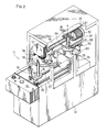
- the new apparatus is shown as a whole with number 10 and comprises (figure 2) a casing 12 with a control panel 14.
- a unit 16 for supporting and moving the last is mounted inside the casing.
- the unit will not be described in detail as it is already known.
- it comprises a pair of supports 18 and 19 (for fixing the last and for its toe-end to rest on) on a rotating head 20, which slides on horizontal bars 22.
- the head 20 automatically completes a run equal at least to the length of the footwear, a rotation through 180°, a further run in the reversed direction as far as the starting point and a further rotation through 180°.
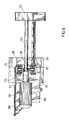
- a fixed framework 26 with its upper end ending with a platform 28 is also mounted inside the casing, and a bush 30 (figure 3) on the platform defines a vertical axis of rotation a and receives a vertical support pin 32 which is rotatable around the said axis.
- the said pin is integral with a frame 34 extending horizontally and supporting a horizontal pin 36 on vertical arms 35, said pin defining a horizontal axis of rotation b .
- a body 38 is pivoted onto the pin 36.
- an inclination rod 40 is fixed, connected to one end of a spring 42 (the other end of which is fixed to the casing) and to a shaft of a cylinder 44 (fixed to the frame 34).
- the cylinder adjusts the angle of the rod 40 and body 38 with respect to the frame 34, and is opposed by the spring 42.
- the body 38 integrally and projectingly supports a brush supporting arm 46 and at the top a small pin 48.
- the frame 34 supports a brush rotation motor 50, to the output shaft 51 of which a brush rotation shaft 52 is connected, by means of an articulated joint 53 (figure 8), which allows for members 51, 52 to be set at an angle to each other while still allowing them to rotate integrally.
- a bracket 54 connects the brush supporting arm 46 to the brush rotation shaft 52.
- the brush which is already known, is shown with number 56, while number 57 shows a hood, which is also known, supported by the usual means, and number 58 shows a deposit suction tube.
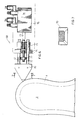
- the tracer framework or mounting shown as a whole with 60 (figure 5), is supported free to rotate on the pin 48.
- Such mounting comprises an arm 61, 62, fixed to a rod 64, which supports, possibly by means of adjusting screws 65, 66, (already known and therefore not described), a tongue 67, integral with the tracer unit 68.
- the latter comprises a tapered or point-shaped tracer head 70 (figure 7), which is preferably triangular in plan view, and is integral with parallel rods 72, 72.
- a cylinder-piston unit 74 is supported on the plate 76 and has a threaded shaft 75 made integral with the block 73.
- the position of a threaded nut 77 on the shaft 75 can be set to define a limit of the run of the tracer head.
- the position of the head is set according to the footwear by means of the cylinder 74.
- the plate 76 is supported on a slider 90 through an articulated shock-absorber device 92, which is already known and therefore not described, brought back into position by means of a spring 94.
- the slider 90 is supported on sliding guides 96 on the tongue 67 and is moved from an extended position (drawn in a continuous line in figure 4a) and a retracted position (drawn in chain lines) by means of a cylinder 98 and the relative shaft 100, controlled from the rotating head 20.
- the invention also foresees that the member 90 can be fixed to the tongue 67 (figure 2).
- the tracer unit is pushed against the last by a means 82, which can be a spring or a cylinder-piston unit, whose shaft is integral with the arm 61, 62.
- the movable element of a potentiometer 80 is also integral with the same arm and is supported by a support 83 integral with the fixed casing 28.
- the potentiometer 80 is connected to an electropneumatic transducer 84, which is already known and visible in the block diagram in figure 5, for example a EIT200 type of the SMC Corporation, which in consequence operates a cylinder-piston unit 86 (figure 8), located between the bar 88 integral with the casing 26 and the frame 34, in such a way as to operate the rotation of the latter.
- the rotating head 20 travels along the bars 22 with the double support 18, 19, first in one direction and then, after rotating through 180°, in the other direction.
- the motor sets the brush 56 in rotation and this is pressed onto the last 1 at the desired pressure, by the action of the cylinder-piston unit 44 and of the opposing spring 42.
- the head 70 of the tracer 68 rests against the last, and the horizontal displacements detected by the tracer are transmitted to the potentiometer 80 which sends a corresponding electric signal to the electropneumatic transducer 84, which operates the cylinder-piston unit 86 in a corresponding way, which thus determines the rotation of the brush supporter arm 46 and therefore of the brush shaft 52 around the axis a , in order to adjust its position to the configuration detected by the tracer.
- the position of the head 70 of the tracer in figure 4a will be adjusted by means of the cylinder 98, so as to be "in advance" of the position of the brush; that is to say, with reference to figure 4a, when the last 1 is running in the direction F1, the head will be in the position shown in dots and dashes; the rotation of the head 20 at the end of the run will move the head, by means of the cylinder 98, into the position drawn with a continuous line, where it will follow the last during the movement in the direction F2.
Landscapes
- Engineering & Computer Science (AREA)
- Mechanical Engineering (AREA)
- Automation & Control Theory (AREA)
- Footwear And Its Accessory, Manufacturing Method And Apparatuses (AREA)
- Treatment Of Fiber Materials (AREA)
- Preliminary Treatment Of Fibers (AREA)
Applications Claiming Priority (2)
| Application Number | Priority Date | Filing Date | Title |
|---|---|---|---|
| IT22420A IT1237138B (it) | 1989-11-17 | 1989-11-17 | Apparecchiatura e procedimento per eseguire una lavorazione, per esempio una cardatura, sul bordo di una tomaia, sotto la guida di un tastatore. |
| IT2242089 | 1989-11-17 |
Publications (2)
| Publication Number | Publication Date |
|---|---|
| EP0428974A2 true EP0428974A2 (de) | 1991-05-29 |
| EP0428974A3 EP0428974A3 (en) | 1992-10-21 |
Family
ID=11196063
Family Applications (1)
| Application Number | Title | Priority Date | Filing Date |
|---|---|---|---|
| EP19900121611 Withdrawn EP0428974A3 (en) | 1989-11-17 | 1990-11-12 | An apparatus and process for carrying out a tracer-guided operation, for example a roughing operation, on the edge of an upper |
Country Status (2)
| Country | Link |
|---|---|
| EP (1) | EP0428974A3 (de) |
| IT (1) | IT1237138B (de) |
Cited By (3)
| Publication number | Priority date | Publication date | Assignee | Title |
|---|---|---|---|---|
| WO1996019129A1 (en) * | 1994-12-22 | 1996-06-27 | British United Shoe Machinery Limited | Machine for performing a roughing operation progressively along marginal portions of a shoe bottom |
| EP1472946A1 (de) * | 2003-05-02 | 2004-11-03 | Officina Meccanica B.D.F. S.P.A. | Schockabsorber für die Bürste einer Karde, in einer Kardiermaschine für Schuhschäfte |
| CN105286215A (zh) * | 2015-11-09 | 2016-02-03 | 天津马士通机械设备有限公司 | 一种鞋帮旋转式起毛机及其加工方法 |
Family Cites Families (5)
| Publication number | Priority date | Publication date | Assignee | Title |
|---|---|---|---|---|
| US3298048A (en) * | 1963-08-14 | 1967-01-17 | Ind Shoe Machinery Corp | Machine for roughening the margin of the bottom of a shoe |
| US3769649A (en) * | 1969-06-02 | 1973-11-06 | Usm Corp | Automatic shoe machinery and operation of the same |
| US4020660A (en) * | 1975-08-28 | 1977-05-03 | International Shoe Machine Corporation | Roughing machine having tool position adjusting mechanism |
| US4691398A (en) * | 1983-09-22 | 1987-09-08 | Leader Company Limited | Shoe making machine |
| IT1173405B (it) * | 1984-02-29 | 1987-06-24 | Torti Spa | Macchina cardatrice particolarmente per la carteggiatura del bordo inferiore delle tomaie |
-
1989
- 1989-11-17 IT IT22420A patent/IT1237138B/it active IP Right Grant
-
1990
- 1990-11-12 EP EP19900121611 patent/EP0428974A3/en not_active Withdrawn
Cited By (3)
| Publication number | Priority date | Publication date | Assignee | Title |
|---|---|---|---|---|
| WO1996019129A1 (en) * | 1994-12-22 | 1996-06-27 | British United Shoe Machinery Limited | Machine for performing a roughing operation progressively along marginal portions of a shoe bottom |
| EP1472946A1 (de) * | 2003-05-02 | 2004-11-03 | Officina Meccanica B.D.F. S.P.A. | Schockabsorber für die Bürste einer Karde, in einer Kardiermaschine für Schuhschäfte |
| CN105286215A (zh) * | 2015-11-09 | 2016-02-03 | 天津马士通机械设备有限公司 | 一种鞋帮旋转式起毛机及其加工方法 |
Also Published As
| Publication number | Publication date |
|---|---|
| IT8922420A0 (it) | 1989-11-17 |
| IT1237138B (it) | 1993-05-24 |
| EP0428974A3 (en) | 1992-10-21 |
| IT8922420A1 (it) | 1991-05-17 |
Similar Documents
| Publication | Publication Date | Title |
|---|---|---|
| CA1232519A (en) | Cutting device for a multi-dimensional bending apparatus | |
| US5239853A (en) | Device for bending sheet metal | |
| EP0143753A2 (de) | Maschine zum Glätten von Holztafeln | |
| EP0126037A2 (de) | Vorrichtung zum Schneiden von Flachglasscheiben nach einem programmierten Profil | |
| JPH0747294B2 (ja) | 単層又は多層のウエブから可撓性チューブを形成するための装置 | |
| US4324118A (en) | Machine for roughing a peripheral vamp edge of a shoe | |
| EP0428974A2 (de) | Apparat und Verfahren zur Durchführung einer durch einen Fühler gesteuerten Bearbeitung, z.B. Aufrauhen an der Kante eines Schuhoberteils | |
| WO1995031596A2 (en) | Shearing machine | |
| CA1037718A (en) | Billet grinding machine | |
| HUT63476A (en) | Tangential grinding machine particularly for iron rails | |
| EP0140394B1 (de) | Einrichtung zum Biegen von Blechen | |
| EP0596570B1 (de) | Vorrichtung zum Aufrauhen und Kleben von Schuhen | |
| JP3122126B2 (ja) | 金属薄板を反対方向に屈曲する方法 | |
| US4322864A (en) | Binding machine for the application of a strip of flexible material around the outline of thin articles, particularly for edging parts for boots and shoes | |
| JP2894514B2 (ja) | 折曲げ機 | |
| JP3504329B2 (ja) | 折曲げ加工装置 | |
| JPS6238076B2 (de) | ||
| US2610404A (en) | Three-dimensional pantographic reproducing machine | |
| CN119426695B (zh) | 一种数控切割机及其控制方法 | |
| EP0370973A2 (de) | Trimmkopf zur Endfertigung von Verbundscheiben | |
| US2933745A (en) | Device for automatically smoothing in the rear strip in manufacturing rubber boots or other shoes | |
| JPH01289513A (ja) | 板材折曲げ加工機 | |
| EP0750462A1 (de) | Maschine zur fortschreitenden bearbeitung entlang ausgewählter bereiche von artikeln | |
| SU959985A1 (ru) | Ленточно-шлифовальный станок | |
| CN220574924U (zh) | 一种磨齿机砂轮修整机构 |
Legal Events
| Date | Code | Title | Description |
|---|---|---|---|
| PUAI | Public reference made under article 153(3) epc to a published international application that has entered the european phase |
Free format text: ORIGINAL CODE: 0009012 |
|
| AK | Designated contracting states |
Kind code of ref document: A2 Designated state(s): DE ES FR GB IT |
|
| PUAL | Search report despatched |
Free format text: ORIGINAL CODE: 0009013 |
|
| AK | Designated contracting states |
Kind code of ref document: A3 Designated state(s): DE ES FR GB IT |
|
| STAA | Information on the status of an ep patent application or granted ep patent |
Free format text: STATUS: THE APPLICATION IS DEEMED TO BE WITHDRAWN |
|
| 18D | Application deemed to be withdrawn |
Effective date: 19930422 |