EP0428989A2 - Appareil pour le chargement des billettes et éventuellement des disques de poussée dans des presses d'extrusion de métaux horizontales - Google Patents
Appareil pour le chargement des billettes et éventuellement des disques de poussée dans des presses d'extrusion de métaux horizontales Download PDFInfo
- Publication number
- EP0428989A2 EP0428989A2 EP90121768A EP90121768A EP0428989A2 EP 0428989 A2 EP0428989 A2 EP 0428989A2 EP 90121768 A EP90121768 A EP 90121768A EP 90121768 A EP90121768 A EP 90121768A EP 0428989 A2 EP0428989 A2 EP 0428989A2
- Authority
- EP
- European Patent Office
- Prior art keywords
- charging
- press
- tines
- cradles
- charging cradle
- Prior art date
- Legal status (The legal status is an assumption and is not a legal conclusion. Google has not performed a legal analysis and makes no representation as to the accuracy of the status listed.)
- Granted
Links
Images

Classifications
-
- B—PERFORMING OPERATIONS; TRANSPORTING
- B21—MECHANICAL METAL-WORKING WITHOUT ESSENTIALLY REMOVING MATERIAL; PUNCHING METAL
- B21C—MANUFACTURE OF METAL SHEETS, WIRE, RODS, TUBES, PROFILES OR LIKE SEMI-MANUFACTURED PRODUCTS OTHERWISE THAN BY ROLLING; AUXILIARY OPERATIONS USED IN CONNECTION WITH METAL-WORKING WITHOUT ESSENTIALLY REMOVING MATERIAL
- B21C23/00—Extruding metal; Impact extrusion
- B21C23/21—Presses specially adapted for extruding metal
- B21C23/212—Details
-
- B—PERFORMING OPERATIONS; TRANSPORTING
- B21—MECHANICAL METAL-WORKING WITHOUT ESSENTIALLY REMOVING MATERIAL; PUNCHING METAL
- B21C—MANUFACTURE OF METAL SHEETS, WIRE, RODS, TUBES, PROFILES OR LIKE SEMI-MANUFACTURED PRODUCTS OTHERWISE THAN BY ROLLING; AUXILIARY OPERATIONS USED IN CONNECTION WITH METAL-WORKING WITHOUT ESSENTIALLY REMOVING MATERIAL
- B21C33/00—Feeding extrusion presses with metal to be extruded ; Loading the dummy block
Definitions
- Blocks and, if necessary, press disks are loaded into horizontal metal extrusion presses by means of devices consisting of at least one loading cradle, but usually two or more charging cradles arranged one behind the other along the press axis, each of which can be inserted into the press axis carried by a swivel arm or a push rod and can be brought out of it again.
- Loading can take place between the block receiver and the press ram, for which purpose a corresponding stroke of the press ram is required.
- the block pick-up of the extrusion press which is provided with a displacement device, is first moved via the press ram (DE-PS 519 038) or, in the case of metal extrusion presses set up for indirect pressing, optionally via the die ram (DE-OS 30 29 234), so that the space between the Press tool and the ram is accessible.
- the block receiver is moved back and picks up the block.
- the feed of the block receiver is usually interrupted for the time a charging cradle is being deployed in order to rule out a collision between the block receiver and the charging cradle.
- the charging cradle facing the block receiver is also different from the other charging cradle based on the Support arms according to DE-PS 519 038 slidably arranged, the width of the charging cradles determining the surface-friendly support of the blocks limits the possible space gain.
- the invention is based on the devices for loading blocks and, if appropriate, press disks into lying metal extrusion presses, which have two or more loading trays arranged one behind the other along the press axis and carried by swivel arms or push rods, which can be inserted into the press axis and can be removed again from the press axis, and of which at least the second charging cradle and optionally the further charging cradles can be displaced in the direction of the press axis.
- the displaceability of one charging cradle against the other presupposes a distance between the charging cradles, the width of the charging cradles taken together not being allowed to be more than the smallest block length.
- the distance between the charging cradles does not allow the loading of divided blocks, the sections of which do not bridge the gap between the charging cradles sufficiently.
- the loss of time is a further disadvantage of the known block loaders.
- the object of the invention is to be able to load blocks of different lengths, divided blocks and blocks together with a press disk safely and without interruption with charging trays of sufficient width.
- This object is achieved in that the charging cradles are fork-shaped with offset prongs and gaps and each charging cradle is telescopically retractable into the gap between the tines of the other charging cradle or charging cradles.
- the charging cradles can be moved together to a total width that is less than the width of the individual charging cradles combined. This eliminates the need to drive out a charging cradle and thus stop the component of the press that can be moved for loading, for example the block receiver.
- a complete collapse of the charging cradles to the width of a single charging cradle is achieved in that after another Feature of the invention, the tines and the gaps between the tines of the charging cradles extend over their entire axial width and the adjacent yokes summarizing the tines are connected offset with the tines assigned to them outside the vicinity of tines and gaps, the width of the The yokes taken together do not exceed the axial width of the charging cradles, which corresponds to the length of the tines.
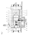
- the metal extrusion press shown in FIG. 1 consists of a cylinder spar 1, a counter spar 2 and anchors 3 connecting these.
- Guides 4 on the anchors 3 carry a running spar 5 which is guided by a plunger 7 guided and acted upon in the cylinder 6 of the cylinder spar 1 in the direction of the press axis is moved backwards in the pressing direction and by piston-cylinder units 8.
- the barrel 5 carries one Press ram 9.
- the guides 4 carry a spar 10 which is provided with a block receiver 11 and can be moved by piston-cylinder units 12 in the direction of the press axis.
- a die 14 is fastened to the counter beam 2 in a holder 13. To load a block to be pressed, the spar 10 is pushed with the block receiver 11 over the press ram 9, so that the space between the die 14 and a press disk 15 on the end face of the press ram 9 is exposed.
- the device for loading blocks consists of a bearing block 16 which rotatably carries a shaft 18 in two bearings 17, which shaft is formed between the bearings 17 as a square or spline shaft.
- the shaft 18 is pivoted in one direction or the other via the drive lever 19.
- swivel arm 24 and 25 On the shaft 18, two swivel arms 24 and 25 are attached in a rotationally fixed manner, the swivel arm 24 also being fastened axially to the shaft 18, while the swivel arm 25 is axially displaceably seated on the shaft 18 and by a piston-cylinder unit 26 which is in the drive lever 19 27 is supported, is moved axially.
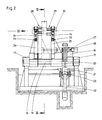
- Each swivel arm 24 and 25 carries a charging cradle 28, 29.
- the swivel arms 24 and 25 To accommodate a block 30, the swivel arms 24 and 25 are in the swivel position shown in dashed lines in FIG. 3, in which they take over the metal blocks 30, which are conveyed by an oven and heated to the pressing temperature.
- the swivel arms 24 and 25 are pivoted via the shaft 18 in such a way that the block 30 lying in their charging cradles 28 and 29 reaches the free tree between the die 14 and the pressure plate 15 in the press axis.
- the spar 10 with the block receiver 11 is moved towards the die 14 by means of the piston-cylinder units 12, the block receiver 11 being placed over the block 30.
- the swivel arm 25 is axially displaced on the shaft 18 by means of the piston-cylinder unit 26, up to the position shown in broken lines in FIG.
- the charging cradles 28 and 29 are fork-shaped and the charging cradle 28 consists of tines 31 and the charging cradle 29 consists of tines 32.
- the tines 31 are composed of yoke pieces 28a, 28b and the tines 32 are composed of yoke pieces 29a and 29b, the yoke piece 28a the end of the swivel arm 24 and the yoke piece 29a forms the end of the swivel arm 25, the yoke piece 28b is pivotable about an axis 33 in the swivel arm 25 and the yoke piece 29b about an axis 33.
- the yoke pieces 28b and 29b are each pivoted by a piston-cylinder unit 34 which are articulated on the pivot arms 24 and 25, respectively.
- the charging cradle 29 overlaps completely with the charging cradle 28 in the position of the swivel arm 25 shown in broken lines, which is due to the fork-like design of the charging cradles 28 and 29 with an offset arrangement of the tines 31 and 32, in which the tines 31 the charging cradle 28 face the gaps between the prongs 32 of the charging cradle 29 and vice versa.
- the piston-cylinder units 34 are acted upon jointly on both swivel arms 24 and 25, so that the yoke pieces 28b and 29b jointly swivel about their axes 33 into the position shown in broken lines in FIG. 3, so that the swivel arms 24 and 25 with the open arms Charging cradles 28 and 29 can be pivoted together past the block 30.
- a metal extrusion press in which a press disk 15 is used, which is firmly connected to the press ram 9, that is, it is not loaded with the block 30 for each pressing operation, as is common with light metal extrusion presses . If you want to work with a loose press disk 15, shorter blocks or longer charging cradles must be used to ensure that there is also space for the pressing disks on the charging cradles.
- the length of the charging cradles 28 and 29 is determined from the sufficient support for the blocks 30 to be loaded and the length of the blocks 30 determines the distance A between the charging cradles 28 and 29 in the starting position.
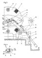
- more than two charging cradles can also be provided and designed according to the principle of the invention, as is shown in principle for three charging cradles in FIGS. 5 and 6.
- FIG. 5 shows the three charging cradles in an overlapping position
- FIG. 6 shows an opened position that has been moved apart.
- the swivel arms with the yoke pieces carrying the tines are denoted by 35, 36 and 37, the swivel arm 35 being a charging cradle 39 formed from prongs 38, the swiveling arm 36 being a charging cradle 41 formed from prongs 40 and the swivel arm 31 being a charging cradle 43 formed from prongs 42 wearing.
- the tines 38, 40, 42 are in turn offset from one another with the yoke pieces of the swivel arms 35, 36 and 37 so that a displacement of the swivel arms 36 and 37 according to arrows C and D leads to a complete overlap of the tines 38, 40 and 42.
Landscapes
- Engineering & Computer Science (AREA)
- Mechanical Engineering (AREA)
- Press Drives And Press Lines (AREA)
Applications Claiming Priority (2)
| Application Number | Priority Date | Filing Date | Title |
|---|---|---|---|
| DE3938790 | 1989-11-23 | ||
| DE3938790A DE3938790C1 (fr) | 1989-11-23 | 1989-11-23 |
Publications (3)
| Publication Number | Publication Date |
|---|---|
| EP0428989A2 true EP0428989A2 (fr) | 1991-05-29 |
| EP0428989A3 EP0428989A3 (en) | 1991-12-27 |
| EP0428989B1 EP0428989B1 (fr) | 1994-07-13 |
Family
ID=6394033
Family Applications (1)
| Application Number | Title | Priority Date | Filing Date |
|---|---|---|---|
| EP90121768A Expired - Lifetime EP0428989B1 (fr) | 1989-11-23 | 1990-11-14 | Appareil pour le chargement des billettes et éventuellement des disques de poussée dans des presses d'extrusion de métaux horizontales |
Country Status (2)
| Country | Link |
|---|---|
| EP (1) | EP0428989B1 (fr) |
| DE (2) | DE3938790C1 (fr) |
Cited By (5)
| Publication number | Priority date | Publication date | Assignee | Title |
|---|---|---|---|---|
| EP0791413A1 (fr) * | 1996-02-26 | 1997-08-27 | Sms Schloemann Gmbh | Appareil pour le chargement des billettes et éventuellement des disques de poussée dans des presses horizontales d'extrusion de métaux |
| DE10227488B3 (de) * | 2002-06-19 | 2004-02-12 | Sms Eumuco Gmbh | Strang-und Rohrpresse |
| WO2004076088A1 (fr) * | 2003-02-27 | 2004-09-10 | Danieli & C. Officine Meccaniche S.P.A. | Chargeur de billette pour des presses d'extrusion |
| WO2005110636A1 (fr) * | 2004-05-10 | 2005-11-24 | Sms Eumuco Gmbh | Presse a extruder les barres et les tubes |
| CN107639126A (zh) * | 2017-11-09 | 2018-01-30 | 江苏启力锻压机床有限公司 | 卧式双模冷挤压机构及成形生产工艺 |
Families Citing this family (1)
| Publication number | Priority date | Publication date | Assignee | Title |
|---|---|---|---|---|
| EP0574592B1 (fr) * | 1992-04-15 | 1994-03-16 | SMS Hasenclever GmbH | Appareil pour le chargement des bilettes et éventuellement des disques de poussée dans des presses horizontales d'extrusion de métaux |
Family Cites Families (4)
| Publication number | Priority date | Publication date | Assignee | Title |
|---|---|---|---|---|
| DE519038C (de) * | 1929-02-05 | 1931-02-23 | Fried Krupp Grusonwerk Akt Ges | Liegende Strangpresse mit beweglicher Blocktragvorrichtung |
| DE1156374B (de) * | 1959-09-25 | 1963-10-31 | Hydraulik Gmbh | Blockhaltevorrichtung fuer liegende Metallstrangpresse |
| US3416349A (en) * | 1966-06-29 | 1968-12-17 | Baldwin Lima Hamilton Corp | Extrusion apparatus and method |
| DE3029234A1 (de) * | 1980-08-01 | 1982-04-01 | Schloemann-Siemag AG, 4000 Düsseldorf | Metallstrangpresse zum indirekten und direkten verpressen von metallen mit einer mit dem aufnehmerhalter verbundenen vorrichtung zum abtrennen des pressrestes und zum auswechseln von matrizen |
-
1989
- 1989-11-23 DE DE3938790A patent/DE3938790C1/de not_active Expired - Lifetime
-
1990
- 1990-11-14 DE DE59006422T patent/DE59006422D1/de not_active Expired - Lifetime
- 1990-11-14 EP EP90121768A patent/EP0428989B1/fr not_active Expired - Lifetime
Cited By (11)
| Publication number | Priority date | Publication date | Assignee | Title |
|---|---|---|---|---|
| EP0791413A1 (fr) * | 1996-02-26 | 1997-08-27 | Sms Schloemann Gmbh | Appareil pour le chargement des billettes et éventuellement des disques de poussée dans des presses horizontales d'extrusion de métaux |
| US5823038A (en) * | 1996-02-26 | 1998-10-20 | Sms Eumuco Gmbh | Apparatus for loading a billet and, if necessary, a pressing disc into a horizontal metal extrusion press |
| DE10227488B3 (de) * | 2002-06-19 | 2004-02-12 | Sms Eumuco Gmbh | Strang-und Rohrpresse |
| WO2004000538A3 (fr) * | 2002-06-19 | 2004-02-26 | Sms Eumuco Gmbh | Presse a filer et d'extrusion pour tubes |
| US7216522B2 (en) | 2002-06-19 | 2007-05-15 | Sms Eumuco Gmbh | Extruding and pipe press |
| WO2004076088A1 (fr) * | 2003-02-27 | 2004-09-10 | Danieli & C. Officine Meccaniche S.P.A. | Chargeur de billette pour des presses d'extrusion |
| CN1326641C (zh) * | 2003-02-27 | 2007-07-18 | 达涅利机械工业有限公司 | 用于挤压机的坯料装载设备 |
| US7357383B2 (en) | 2003-02-27 | 2008-04-15 | Danieli & C. Officine Meccaniche S.P.A. | Billet loader for extrusion presses |
| WO2005110636A1 (fr) * | 2004-05-10 | 2005-11-24 | Sms Eumuco Gmbh | Presse a extruder les barres et les tubes |
| US7448245B2 (en) | 2004-05-10 | 2008-11-11 | Sms Eumuco Gmbh | Extruding press for billets and tubes |
| CN107639126A (zh) * | 2017-11-09 | 2018-01-30 | 江苏启力锻压机床有限公司 | 卧式双模冷挤压机构及成形生产工艺 |
Also Published As
| Publication number | Publication date |
|---|---|
| DE3938790C1 (fr) | 1990-12-06 |
| EP0428989A3 (en) | 1991-12-27 |
| DE59006422D1 (de) | 1994-08-18 |
| EP0428989B1 (fr) | 1994-07-13 |
Similar Documents
| Publication | Publication Date | Title |
|---|---|---|
| DE3423283C2 (fr) | ||
| EP0419441B1 (fr) | Appareil de pliage pour barres de fer à béton | |
| EP3778049B1 (fr) | Machine d'usinage pour pièces de matière plate dotée d'une unité de pose et procédé correspondant | |
| DE3404553C2 (de) | Handhabungseinrichtung, insbesondere zum Be- und Entladen von Werkzeugmaschinen | |
| DE3519970C2 (fr) | ||
| EP0144981A2 (fr) | Procédé et dispositif pour le forgeage de vilebrequins sur des presses | |
| DE3241746C2 (fr) | ||
| DE3938790C1 (fr) | ||
| DE2411744A1 (de) | Presse zum pressverbinden eines mindestens teilweise drahtfoermigen teiles mit einem abschlussteil | |
| DE19724635C2 (de) | Werkzeugmaschine mit Werkzeugauswechselvorrichtung | |
| DE2754176A1 (de) | Vorrichtung zum beladen von werkzeugmaschinen, insbesondere drehmaschinen | |
| EP0574592B1 (fr) | Appareil pour le chargement des bilettes et éventuellement des disques de poussée dans des presses horizontales d'extrusion de métaux | |
| DE10223897A1 (de) | Werkzeugwechselvorrichtung für Pressen | |
| DE2843531C2 (de) | Maschine zum Herstellen von gitterträgerartigen Bewehrungsgebilden für Stahlbeton | |
| DE2538201C3 (de) | Mundstückwechselvorrichtung für eine Strangpresse | |
| DE102009007151B4 (de) | Entgratpresse mit einer Vorrichtung zur Entnahme eines entgrateten Werkstücks, Entnahmevorrichtung für diese Entgratpresse sowie Verfahren zur Entnahme eines entgrateten Werkstücks aus dieser Entgratpresse | |
| DE3508354C2 (de) | Maschine zum Aufquetschbestücken von Kabeladerenden mit Aderendhülsen od.dgl. Anschlußelementen | |
| EP0243787B1 (fr) | Système de transport pour la circulation des grains de poussée et des matrices des presses à filage aménagées pour presser directement et indirectement | |
| DE8913819U1 (de) | Vorrichtung zum Laden von Blöcken und gegebenenfalls Preßscheiben in liegende Metallstrangpressen | |
| DE2229738C3 (de) | Indirektstrangpresse | |
| EP0123976B1 (fr) | Chariot réglable pour cylindre à imprimer | |
| DE3108337A1 (de) | Strangpressmaschine und verfahren zum betrieb einer strangpressmaschine | |
| DE9205216U1 (de) | Vorrichtung zum Laden von Blöcken und gegebenenfalls Preßscheiben in eine liegende Metallstrangpresse | |
| EP0675771B1 (fr) | Procede pour le chargement d'une billette dans une presse a extruder les metaux | |
| DE1222593B (de) | Maschine zum Entfernen der Spaltstoffplatten von einem gebrauchten Brennstoffbehaelter fuer einen Kernreaktor |
Legal Events
| Date | Code | Title | Description |
|---|---|---|---|
| PUAI | Public reference made under article 153(3) epc to a published international application that has entered the european phase |
Free format text: ORIGINAL CODE: 0009012 |
|
| 17P | Request for examination filed |
Effective date: 19901114 |
|
| AK | Designated contracting states |
Kind code of ref document: A2 Designated state(s): DE FR GB IT |
|
| PUAL | Search report despatched |
Free format text: ORIGINAL CODE: 0009013 |
|
| AK | Designated contracting states |
Kind code of ref document: A3 Designated state(s): DE FR GB IT |
|
| 17Q | First examination report despatched |
Effective date: 19930222 |
|
| ITF | It: translation for a ep patent filed | ||
| GRAA | (expected) grant |
Free format text: ORIGINAL CODE: 0009210 |
|
| AK | Designated contracting states |
Kind code of ref document: B1 Designated state(s): DE FR GB IT |
|
| REF | Corresponds to: |
Ref document number: 59006422 Country of ref document: DE Date of ref document: 19940818 |
|
| GBT | Gb: translation of ep patent filed (gb section 77(6)(a)/1977) |
Effective date: 19940727 |
|
| ET | Fr: translation filed | ||
| PLBE | No opposition filed within time limit |
Free format text: ORIGINAL CODE: 0009261 |
|
| STAA | Information on the status of an ep patent application or granted ep patent |
Free format text: STATUS: NO OPPOSITION FILED WITHIN TIME LIMIT |
|
| 26N | No opposition filed | ||
| PGFP | Annual fee paid to national office [announced via postgrant information from national office to epo] |
Ref country code: GB Payment date: 20011012 Year of fee payment: 12 |
|
| REG | Reference to a national code |
Ref country code: GB Ref legal event code: IF02 |
|
| PG25 | Lapsed in a contracting state [announced via postgrant information from national office to epo] |
Ref country code: GB Free format text: LAPSE BECAUSE OF NON-PAYMENT OF DUE FEES Effective date: 20021114 |
|
| GBPC | Gb: european patent ceased through non-payment of renewal fee | ||
| PGFP | Annual fee paid to national office [announced via postgrant information from national office to epo] |
Ref country code: DE Payment date: 20091120 Year of fee payment: 20 |
|
| PGFP | Annual fee paid to national office [announced via postgrant information from national office to epo] |
Ref country code: FR Payment date: 20091201 Year of fee payment: 20 Ref country code: IT Payment date: 20091126 Year of fee payment: 20 |
|
| PG25 | Lapsed in a contracting state [announced via postgrant information from national office to epo] |
Ref country code: DE Free format text: LAPSE BECAUSE OF EXPIRATION OF PROTECTION Effective date: 20101114 |