EP0429008A1 - Porte-outil ajustable - Google Patents
Porte-outil ajustable Download PDFInfo
- Publication number
- EP0429008A1 EP0429008A1 EP90121892A EP90121892A EP0429008A1 EP 0429008 A1 EP0429008 A1 EP 0429008A1 EP 90121892 A EP90121892 A EP 90121892A EP 90121892 A EP90121892 A EP 90121892A EP 0429008 A1 EP0429008 A1 EP 0429008A1
- Authority
- EP
- European Patent Office
- Prior art keywords
- arm
- supporting arm
- disk
- fork
- orientatable
- Prior art date
- Legal status (The legal status is an assumption and is not a legal conclusion. Google has not performed a legal analysis and makes no representation as to the accuracy of the status listed.)
- Granted
Links
- 238000012423 maintenance Methods 0.000 claims abstract description 7
- 230000008878 coupling Effects 0.000 claims abstract description 3
- 238000010168 coupling process Methods 0.000 claims abstract description 3
- 238000005859 coupling reaction Methods 0.000 claims abstract description 3
- 230000000284 resting effect Effects 0.000 claims description 3
- 230000014759 maintenance of location Effects 0.000 claims 1
- 239000000523 sample Substances 0.000 description 3
- 230000000694 effects Effects 0.000 description 1
- 238000000605 extraction Methods 0.000 description 1
- 230000000670 limiting effect Effects 0.000 description 1
- 239000002184 metal Substances 0.000 description 1
- 230000000737 periodic effect Effects 0.000 description 1
- 230000001681 protective effect Effects 0.000 description 1
Images

Classifications
-
- B—PERFORMING OPERATIONS; TRANSPORTING
- B25—HAND TOOLS; PORTABLE POWER-DRIVEN TOOLS; MANIPULATORS
- B25J—MANIPULATORS; CHAMBERS PROVIDED WITH MANIPULATION DEVICES
- B25J17/00—Joints
- B25J17/02—Wrist joints
- B25J17/0241—One-dimensional joints
- B25J17/025—One-dimensional joints mounted in series
-
- E—FIXED CONSTRUCTIONS
- E01—CONSTRUCTION OF ROADS, RAILWAYS, OR BRIDGES
- E01H—STREET CLEANING; CLEANING OF PERMANENT WAYS; CLEANING BEACHES; DISPERSING OR PREVENTING FOG IN GENERAL CLEANING STREET OR RAILWAY FURNITURE OR TUNNEL WALLS
- E01H1/00—Removing undesirable matter from roads or like surfaces, with or without moistening of the surface
- E01H1/003—Upkeep of road sides along the pavement, for instance cleaning devices particularly for side strips
-
- E—FIXED CONSTRUCTIONS
- E01—CONSTRUCTION OF ROADS, RAILWAYS, OR BRIDGES
- E01H—STREET CLEANING; CLEANING OF PERMANENT WAYS; CLEANING BEACHES; DISPERSING OR PREVENTING FOG IN GENERAL CLEANING STREET OR RAILWAY FURNITURE OR TUNNEL WALLS
- E01H11/00—Control of undesirable vegetation on roads or similar surfaces or permanent ways of railways, e.g. devices for scorching weeds or for applying herbicides; Applying liquids, e.g. water, weed-killer bitumen, to permanent ways
Definitions
- the present invention relates to an orientatable tool support, particularly for railroad maintenance, and more precisely to an orientatable support for shears, cutters and the like for the maintenance of railroads by means of rigged trucks, motorized railcars or self-propelled loaders.
- both the periodic maintenance and the clearing of railroad beds or embankments has to be carried out by cutting and removing hedges, shrubs and the like which flank the railroad beds.
- This maintenance is carried out by means of trucks or motorized railcars or self-propelled loaders provided with a swinging loading arm, and shears or cutters connected to the end of the arm which are actuated by fluid-operated jack systems.
- said shears are connected to the end of said loading arm with the interposition of an orientatable support comprising a supporting arm engaging with a tang in the corresponding seat of a fixing element provided at the end of said loading arm.
- the supporting arm has an end provided with a turret, having a fork-like element articulated thereto by means of a joint having orthogonal pivots or another equivalent elements; said fork supports the shears or cutter element, which is rigidly coupled thereto.
- a first fluid-operated jack and a second fluid-operated jack are provided in order to rotate the fork with respect to the turret about the related pivot and respectively to incline the fork with respect to said turret by rotating about the other pivot.
- the shears therefore have two degrees of freedom with respect to the arm of the loader.
- This arrangement can be insufficient in some operating steps due to the fact that a safety probe is rigidly associated with said shears and is intended to sense contact with the ground to prevent the actuation of said shears for example by means of the automatic movement of the loading arm in order to lift said shears.
- the known arrangement is also disadvantageous due to the fact that for some orientations, which are otherwise compatible with the correct operation of said shears, the safety probe intervenes and limits their use.
- the aim of the present invention is to avoid this disadvantage by means of an orientatable support which, by virtue of an improved efficiency, allows the correct operation of the shears even in the positions in which, with current supports, the unwanted intervention of the safety probe prevents their use.
- Another important object of the present invention is to provide an orientatable support which, by virtue of an improved structural efficiency, allows to orientate the shears so that the cutting plane which contains their jaws is, if necessary, perpendicular or substantially perpendicular to the axis of the logs or branches and the like to be cut, in order to improve the cutting action.
- the present invention provides an orientatable support for shears and the like for the maintenance of railroad beds comprising a supporting arm with a tang for coupling with the seat of a loading arm, a turret at the end of said supporting arm, a fork-like element bearing the tool, said fork-like element being connected to said turret by means of an articulation joint with two pivots having orthogonal axes, and a pair of jacks for angularly moving said fork about the orthogonal axes of the articulation joint, characterized in that the supporting arm comprises two aligned portions between which a joint is interposed whereby to render said aligned portions rotatable with respect to one another about the common longitudinal axis, and in that it comprises a third fluid-operated jack adapted for rotating said aligned portions for longitudinal orientation of the supporting arm.
- the reference numeral 10 generally indicates a self-propelled loader of the known type which comprises wheels 11 with tires and metal rims for combined use on roads and on railroads and a loading arm 12 with multiple pivoted sections 12a-12b which are controlled by respective jacks 13a-13b and with an extractable terminal section 12c.
- the reference numeral 14 indicates the protective housing of the shear-like tool, which is of a per se known type and therefore is not illustrated (for example shears of the "ROUSSEAU SP 120" type), and is supported by the end of the extractable section 12c of the loading arm with the interposition of the orientatable support 15 according to the present invention.
- a feeler roller 14a is rigidly associated with the housing 14 for sensing contact with the ground and for producing, in a per se known manner, the lifting of the arm 12.
- a resting foot 12d is also interposed between the end of the section 12c and the support 15 and is connected to the section 12b of the arm 12 by a connecting rod 16 so that it can assume, by virtue of the extraction and retraction of the section 12c, an idle position (figure 1) or an active position (figure 2).
- the foot 12d In the active position, the foot 12d allows the derailment of the self-propelled loader without having to disassemble the orientatable support 15.
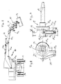
- the orientatable support 15 comprises a supporting arm 17 which ends with a tang 18 engaging with the corresponding seat of a fixing element 19 supported by the section 12c of the loading arm 12.
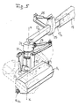
- the arm 17 has, at its free end, a turret 20 to which a fork-like element 22 is connected by means of an articulation joint 21 with orthogonal pivots which define corresponding orthogonal rotation axes X and Y; the shears are rigidly associated with said fork-like element.
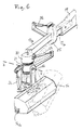
- a first fluid-operated jack 23 and a second fluid-operated jack 24 are provided in order to rotate the fork-like element 22 about the axes X and Y respectively for the Swinging and tilting of the shears, as clearly illustrated in figures 5 and 6.
- the arm 17 is formed by two arm portions 17a-17b arranged so that one is aligned on the extension of the other.
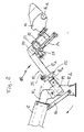
- the portions 17a, 17b are connected by a joint 25 which allows the rotation of the portion 17a with respect to the portion 17b about the common longitudinal axis.
- the joint 25 is advantageously formed by a bell-shaped disk 25a rigidly associated with the portion 17b bearing the tang 15 and in which a disk-shaped plate 25b, rigidly associated with the portion 17a, is contained and is freely rotatable.
- a flange 26 is arranged frontally with respect to the bell-shaped disk and is rigidly coupled thereto by means of bolts or the like in order to be axially coupled to the disk-shaped flange.
- a bracket 27 is also rigidly associated with the portion 17a, and the cylinder 28a of a third jack 28 is articulated thereto by means of an eyelet 27a. The stem of said third jack 28 is articulated to a corresponding eyelet of the bell-shaped disk 25a.
- the arrangement is such that the extension and retraction of the jack 28 correspond to respective rotations of the portion 17a with respect to the portion 17b (figure 4) and consequently of the shears (figure 7) about a third axis Z which coincides with the longitudinal axis of the arm 17, so that the shears have three degrees of movement with respect to the loading arm
Landscapes
- Engineering & Computer Science (AREA)
- Architecture (AREA)
- Civil Engineering (AREA)
- Structural Engineering (AREA)
- Robotics (AREA)
- Mechanical Engineering (AREA)
- Shovels (AREA)
- Forklifts And Lifting Vehicles (AREA)
- Manipulator (AREA)
Applications Claiming Priority (2)
| Application Number | Priority Date | Filing Date | Title |
|---|---|---|---|
| IT5349189 | 1989-11-20 | ||
| IT5349189 | 1989-11-20 |
Publications (2)
| Publication Number | Publication Date |
|---|---|
| EP0429008A1 true EP0429008A1 (fr) | 1991-05-29 |
| EP0429008B1 EP0429008B1 (fr) | 1994-04-06 |
Family
ID=11283170
Family Applications (1)
| Application Number | Title | Priority Date | Filing Date |
|---|---|---|---|
| EP19900121892 Expired - Lifetime EP0429008B1 (fr) | 1989-11-20 | 1990-11-15 | Porte-outil ajustable |
Country Status (3)
| Country | Link |
|---|---|
| EP (1) | EP0429008B1 (fr) |
| DE (1) | DE69007936T2 (fr) |
| ES (1) | ES2050911T3 (fr) |
Cited By (7)
| Publication number | Priority date | Publication date | Assignee | Title |
|---|---|---|---|---|
| US7325777B2 (en) | 2005-02-18 | 2008-02-05 | Gordon Daniel Thiessen | Portable articulating tool support |
| US8801319B2 (en) | 2007-03-13 | 2014-08-12 | Garrett W. Brown | Biased hinge for equipoising support equipment |
| US8827216B2 (en) | 2007-09-17 | 2014-09-09 | Garrett W. Brown | Concentric ring gimbal support system |
| US9156154B2 (en) | 2007-09-17 | 2015-10-13 | Garrett W. Brown | Gimbal assembly for tool support |
| US9204730B2 (en) | 2007-08-30 | 2015-12-08 | Garrett W. Brown | Articulated human arm support |
| US9534730B2 (en) | 2010-08-26 | 2017-01-03 | Garrett W. Brown | Multi-arm gimbal system |
| CN109555053A (zh) * | 2017-09-27 | 2019-04-02 | 山东交通学院 | 一种全转动副三自由度绿化带吸尘清扫机器人 |
Citations (1)
| Publication number | Priority date | Publication date | Assignee | Title |
|---|---|---|---|---|
| DE3731496A1 (de) * | 1987-09-18 | 1989-04-06 | Cronau Heinrich Gmbh | Vorrichtung zum zuschneiden von freistehendem gehoelz |
-
1990
- 1990-11-15 EP EP19900121892 patent/EP0429008B1/fr not_active Expired - Lifetime
- 1990-11-15 DE DE1990607936 patent/DE69007936T2/de not_active Expired - Fee Related
- 1990-11-15 ES ES90121892T patent/ES2050911T3/es not_active Expired - Lifetime
Patent Citations (1)
| Publication number | Priority date | Publication date | Assignee | Title |
|---|---|---|---|---|
| DE3731496A1 (de) * | 1987-09-18 | 1989-04-06 | Cronau Heinrich Gmbh | Vorrichtung zum zuschneiden von freistehendem gehoelz |
Cited By (8)
| Publication number | Priority date | Publication date | Assignee | Title |
|---|---|---|---|---|
| US7325777B2 (en) | 2005-02-18 | 2008-02-05 | Gordon Daniel Thiessen | Portable articulating tool support |
| US8801319B2 (en) | 2007-03-13 | 2014-08-12 | Garrett W. Brown | Biased hinge for equipoising support equipment |
| US10240376B2 (en) | 2007-03-13 | 2019-03-26 | Garrett W. Brown | Biased hinge for equipoising support equipment |
| US9204730B2 (en) | 2007-08-30 | 2015-12-08 | Garrett W. Brown | Articulated human arm support |
| US8827216B2 (en) | 2007-09-17 | 2014-09-09 | Garrett W. Brown | Concentric ring gimbal support system |
| US9156154B2 (en) | 2007-09-17 | 2015-10-13 | Garrett W. Brown | Gimbal assembly for tool support |
| US9534730B2 (en) | 2010-08-26 | 2017-01-03 | Garrett W. Brown | Multi-arm gimbal system |
| CN109555053A (zh) * | 2017-09-27 | 2019-04-02 | 山东交通学院 | 一种全转动副三自由度绿化带吸尘清扫机器人 |
Also Published As
| Publication number | Publication date |
|---|---|
| ES2050911T3 (es) | 1994-06-01 |
| DE69007936T2 (de) | 1994-07-21 |
| DE69007936D1 (de) | 1994-05-11 |
| EP0429008B1 (fr) | 1994-04-06 |
Similar Documents
| Publication | Publication Date | Title |
|---|---|---|
| EP0429008B1 (fr) | Porte-outil ajustable | |
| US5590699A (en) | Mechanism for rotating a tree-felling implement and tree-felling implement therewith | |
| US20080098704A1 (en) | Plant clearing-grinding device | |
| US4355497A (en) | Apparatus for trimming trees | |
| CN113668631A (zh) | 用于机动平地机的转盘组件 | |
| GB2081563A (en) | Grass cutting apparatus | |
| US4162606A (en) | Mower for mounting on the front end of an agricultural vehicle | |
| GB2435802A (en) | A hedge and grass cutter | |
| KR102652868B1 (ko) | 험지주행이 용이한 다관절구조의 4륜 구동 승용형 예초기 | |
| EP3216337B1 (fr) | Équipement pour broyer une matière végétale | |
| EP1327721A1 (fr) | Dispositif de securité pour un bras articulé | |
| JP3749453B2 (ja) | 伐採物移動機構を備えた草刈り機 | |
| EP0769895A1 (fr) | Faucheuse suspendue a un engin de levage | |
| US5048579A (en) | Tree stump cutter | |
| JP7032757B2 (ja) | 自走式作業機 | |
| EP0520576B1 (fr) | Dispositif pour soulever une plante | |
| US6213220B1 (en) | Disc plough improvements | |
| CN114698480A (zh) | 一种枝桠切片车曲型作业臂 | |
| US5044447A (en) | Guide and control device for an agricultural machine | |
| CA2146719C (fr) | Mecanisme de rotation d'un outil d'abattage et outil d'abattage connexe | |
| EP0321164B1 (fr) | Cric de véhicule | |
| CA1080584A (fr) | Fleau pour l'effeuillage et l'ecorcage d'arbres abattus | |
| NL192992C (nl) | Inrichting voor het dragen van een gereedschap. | |
| AU2001221348B8 (en) | Levelling system and method for off-road vehicles | |
| JPS6020528Y2 (ja) | 傾斜地用作業車の走行装置 |
Legal Events
| Date | Code | Title | Description |
|---|---|---|---|
| PUAI | Public reference made under article 153(3) epc to a published international application that has entered the european phase |
Free format text: ORIGINAL CODE: 0009012 |
|
| AK | Designated contracting states |
Kind code of ref document: A1 Designated state(s): DE ES FR |
|
| 17P | Request for examination filed |
Effective date: 19911017 |
|
| 17Q | First examination report despatched |
Effective date: 19930519 |
|
| RAP1 | Party data changed (applicant data changed or rights of an application transferred) |
Owner name: SO.RE.MA. FERROVIARIA S.R.L. |
|
| GRAA | (expected) grant |
Free format text: ORIGINAL CODE: 0009210 |
|
| AK | Designated contracting states |
Kind code of ref document: B1 Designated state(s): DE ES FR |
|
| REF | Corresponds to: |
Ref document number: 69007936 Country of ref document: DE Date of ref document: 19940511 |
|
| REG | Reference to a national code |
Ref country code: ES Ref legal event code: FG2A Ref document number: 2050911 Country of ref document: ES Kind code of ref document: T3 |
|
| ET | Fr: translation filed | ||
| PLBE | No opposition filed within time limit |
Free format text: ORIGINAL CODE: 0009261 |
|
| STAA | Information on the status of an ep patent application or granted ep patent |
Free format text: STATUS: NO OPPOSITION FILED WITHIN TIME LIMIT |
|
| 26N | No opposition filed | ||
| PGFP | Annual fee paid to national office [announced via postgrant information from national office to epo] |
Ref country code: ES Payment date: 20081027 Year of fee payment: 19 |
|
| PGFP | Annual fee paid to national office [announced via postgrant information from national office to epo] |
Ref country code: FR Payment date: 20081029 Year of fee payment: 19 |
|
| PGFP | Annual fee paid to national office [announced via postgrant information from national office to epo] |
Ref country code: DE Payment date: 20081211 Year of fee payment: 19 |
|
| REG | Reference to a national code |
Ref country code: FR Ref legal event code: ST Effective date: 20100730 |
|
| PG25 | Lapsed in a contracting state [announced via postgrant information from national office to epo] |
Ref country code: FR Free format text: LAPSE BECAUSE OF NON-PAYMENT OF DUE FEES Effective date: 20091130 |
|
| PG25 | Lapsed in a contracting state [announced via postgrant information from national office to epo] |
Ref country code: DE Free format text: LAPSE BECAUSE OF NON-PAYMENT OF DUE FEES Effective date: 20100601 |
|
| REG | Reference to a national code |
Ref country code: ES Ref legal event code: FD2A Effective date: 20110301 |
|
| PG25 | Lapsed in a contracting state [announced via postgrant information from national office to epo] |
Ref country code: ES Free format text: LAPSE BECAUSE OF EXPIRATION OF PROTECTION Effective date: 20101116 |
|
| PG25 | Lapsed in a contracting state [announced via postgrant information from national office to epo] |
Ref country code: ES Free format text: LAPSE BECAUSE OF EXPIRATION OF PROTECTION Effective date: 20091116 |