EP0429104A1 - Methode und Vorrichtung zur Herstellung von Radfelgen - Google Patents
Methode und Vorrichtung zur Herstellung von Radfelgen Download PDFInfo
- Publication number
- EP0429104A1 EP0429104A1 EP90202478A EP90202478A EP0429104A1 EP 0429104 A1 EP0429104 A1 EP 0429104A1 EP 90202478 A EP90202478 A EP 90202478A EP 90202478 A EP90202478 A EP 90202478A EP 0429104 A1 EP0429104 A1 EP 0429104A1
- Authority
- EP
- European Patent Office
- Prior art keywords
- clamping band
- spiral
- rim
- cutting
- dowel pins
- Prior art date
- Legal status (The legal status is an assumption and is not a legal conclusion. Google has not performed a legal analysis and makes no representation as to the accuracy of the status listed.)
- Granted
Links
- 238000000034 method Methods 0.000 title claims abstract description 16
- 238000004519 manufacturing process Methods 0.000 title claims abstract description 13
- 238000005520 cutting process Methods 0.000 claims abstract description 31
- 238000004804 winding Methods 0.000 claims abstract description 24
- 230000008602 contraction Effects 0.000 claims description 3
- 241000763859 Dyckia brevifolia Species 0.000 claims 5
- 238000003825 pressing Methods 0.000 claims 1
- 238000006073 displacement reaction Methods 0.000 description 3
- 210000002105 tongue Anatomy 0.000 description 2
- 229910000831 Steel Inorganic materials 0.000 description 1
- 238000000429 assembly Methods 0.000 description 1
- 238000005452 bending Methods 0.000 description 1
- 238000009826 distribution Methods 0.000 description 1
- 239000000428 dust Substances 0.000 description 1
- 230000000694 effects Effects 0.000 description 1
- 230000003287 optical effect Effects 0.000 description 1
- 239000010959 steel Substances 0.000 description 1
- 239000000725 suspension Substances 0.000 description 1
Images


Classifications
-
- B—PERFORMING OPERATIONS; TRANSPORTING
- B60—VEHICLES IN GENERAL
- B60B—VEHICLE WHEELS; CASTORS; AXLES FOR WHEELS OR CASTORS; INCREASING WHEEL ADHESION
- B60B21/00—Rims
-
- B—PERFORMING OPERATIONS; TRANSPORTING
- B21—MECHANICAL METAL-WORKING WITHOUT ESSENTIALLY REMOVING MATERIAL; PUNCHING METAL
- B21D—WORKING OR PROCESSING OF SHEET METAL OR METAL TUBES, RODS OR PROFILES WITHOUT ESSENTIALLY REMOVING MATERIAL; PUNCHING METAL
- B21D53/00—Making other particular articles
- B21D53/26—Making other particular articles wheels or the like
- B21D53/30—Making other particular articles wheels or the like wheel rims
-
- B—PERFORMING OPERATIONS; TRANSPORTING
- B60—VEHICLES IN GENERAL
- B60B—VEHICLE WHEELS; CASTORS; AXLES FOR WHEELS OR CASTORS; INCREASING WHEEL ADHESION
- B60B1/00—Spoked wheels; Spokes thereof
- B60B1/003—Spoked wheels; Spokes thereof specially adapted for bicycles
Definitions
- the invention relates to a method and apparatus for manufacturing wheel rims from a section piece bent into a helical spiral having a plurality of windings.
- a spiral is placed into a clamping band, whereafter the spiral is clamped to the proper diameter and the spiral is cut radially on a place so as to form a plurality of separate rim sections. Then the rim sections are removed from the clamping band and, one by one, they are connected at their ends by dowel pins, for example, or in another way so as to form a closed rim.
- the invention proposes in the first place a method of manufacturing wheel rims, in particular for bicycle wheels, wherein a section piece bent to a helical spiral having a plurality of windings is placed into a clamping band, said clamping band is contracted in circular configuration to the diameter desired for the rim, whereafter the rim spiral is cut into a number of rims corresponding to the number of whole windings, and subsequently, after relief of the clamping band, both ends of each rim section formed by cutting are displaced laterally with respect to each other such that said ends are positioned opposite to each other, whereafter the clamping band is contracted again until both ends of each rim section abut and these ends are interconnected.
- the invention provides an apparatus for manufacturing wheel rims, in particular for bicycle wheels, comprising a clamping band for receiving a section piece bent into a helical spiral having a plurality of windings, means for contracting the clamping band in circular configuration and expanding it again, a cutting means for making a radial cut into the windings of the spiral, cutting clamps on either side of the cutting means for laterally clamping the windings of the spiral prior to cutting them and for displacing both ends of each rim section made by cutting sideways with respect to each other, and means for interconnecting the abutting ends of each rim section.
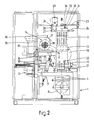
- the embodiment of the apparatus for manufacturing wheel rims from a section piece bent into a helical spiral having a plurality of windings as shown in the drawing includes a frame 1 constructed of posts and girders, that has been placed on the floor.
- the heart of the apparatus consists of a clamping band 2 including an elongated elastically bendable steel plate having two ends and being bent into a substantial circular configuration.
- the clamping band 2 is adjustable to the diameter of the rims to be manufactured owing to the fact that the plate of the clamping band 2 consists of a plurality of plate parts adjustably attached to each other by pin-slot-connections shown at 3.
- the clamping band 2 is secured on both its ends to levers 4 positioned symmetrically to a plane of symmetry A-A and being linked to a girder of the frame 1 by means of a shaft 5 and the lower ends of the levers 4 being in engagement with a spindle shaft 7 by means of a pivotable spindle nut 6.
- the spindle shaft 7 is journalled in the frame and carries a sprocket wheel 8 in its centre between both levers 4, the sprocket wheel 8 being adapted to be rotated by means of a chain and motor (not shown).
- the threads of the spindle shaft 7 have an opposite pitch on both sides of the sprocket wheel 8, so that a rotation of the spindle shaft causes an opposite but equal pivoting movement of the levers 4.
- the maximum pivotal displacement of the levers 4 is determined by stops 9 adjustably fixed to the frame. The pivoting movement of the levers 4 is used for contracting and expanding the clamping band 2 during the manufacture of the wheel rims, as will be
- a cutting clamp 10 consisting of two clamping parts movable to and away from each other symmetrically in longitudinal direction of the clamping band 2, by means of a screw spindle which is drivable by means of an electric motor 12 through a cardan shaft 11 having a sleeve. Furthermore the cutting clamps 10 are adapted to be adjusted with respect to each other in transverse direction of the clamping band 2.
- a circular saw 13 the shaft of which may be driven by an electric motor 14, which is attached to a platform 15, through a chain and sprocket wheels (not shown).
- the platform 15 is pivotable about a pivot shaft 16 connected to the frame 1, by means of a cylinder-piston-assembly 17.
- the circular saw 13 is displaceable with respect to the platform 15 by means of a cylinder-piston-assembly 18.
- a cap 19 in which an underpressure may be produced by an exhaust unit 20 communicating with the cap 19 and adapted to exhaust sawing dust during the sawing operation.
- Two fixtures 21 are pivotally provided in a non-shown manner under the clamping band 2, which fixtures 21 are positioned symmetrically to the plane A-A in the front view of fig. 1, but in the side view of fig. 2 they are offset with respect to each other and with respect to a plane of symmetry B-B a distance in transverse direction of the clamping band 2.
- the fixtures 21 are adapted to engage the free ends of the spiral from which the rims are to be manufactured, for which purpose the free ends of the spiral project through openings 22 in the clamping band 2.
- the clamping band is a supporting girder structure 23 of the frame 1 supporting a cantilevered supporting rod 24 extending through the clamping band 2 near the upper side thereof and being adapted to initially support the spiral placed within the clamping band 2.
- the supporting rod comprises one rear clamping cam 25 and two front clamping cams 26, which are movable towards and away from each other symmetrically by means of a spindle shaft 27 extending through the supporting rod 24 and being driven by an electric motor 29 through a chain drive 28.
- the front clamping cams 26 are provided on pivot arms 30 for pivoting the clamping cams 26 downwardly when they are displaced outwardly so as to enable a rim spiral to be suspended from the supporting rod 24.
- the clamping cams 25 and 26 move symmetrically to the plane B-B (see fig. 2) so that they are adapted to clamp a spiral placed within the clamping band 2 with respect to the plane B-B.
- bracket 31 On the outer side of the clamping band 2 near the upper side thereof is provided a bracket 31 which is linked to a clamping slide 32, which clamping slide 32 is slidably and fixedly provided on a rod 33 attached on one end to the supporting girder structure 23 by means of a pivot 34.
- the bracket 31 and the suspension thereof are intended to prevent tilting or setting movements of the clamping band 2 and can be adapted to each diameter adjustment of the clamping band 2.
- the apparatus further comprises means for automatically supplying and positioning dowel pins which are used for interconnecting the ends of the cut rim sections to form the closed rims.
- These means include a shaking drum 35 having a helical supply path 36 connecting to a conveying chute 37 opening into a vertical cartridge 38 in which a plurality of dowel pins are kept ready in the proper position.
- a slide 39 Under the cartridge 38 is provided a slide 39 which is displaceable between a retracted loading position, in which the slide is loaded with dowel pins from the cartridge 38, and an extended positioning position, in which the dowel pins loaded on the slide 39 are positioned accurately in front of holes in the ends of the formed rim sections to be connected.
- the dowel pins may be moved by the slide 39 both in horizontal and vertical directions.
- the clamping band 2 is contracted into a circle by means of the levers 4 such that the inner diameter of the clamping band 2 corresponds to the desired outer diameter of the rims to be manufactured.
- the cutting clamps 10 centre the spiral with respect to the plane B-B without actually clamping it.
- the fixtures 21 are pressed with great force against the spiral ends which are straight and therefore project out of the openings 22 in the clamping band 2, in order to tighten the spiral against the inner side of the clamping band.
- the exact diameter of the rims to be manufactured is set then.
- Both cutting clamps 10 on both sides of the plane of symmetry A-A subsequently clamp the windings of the spiral to each other, so that the spiral is fixed with respect to the clamping band 2.
- the fixtures 21 are returned outwardly to a starting position and the cutting clamp 10, on the right in fig. 1, is opened.
- the clamping band 2 is then expanded by slightly pivoting the levers 4 in order to remove the strain in the spiral and consequently prevent the windings of the spiral from being pushed against the saw blade of the circular saw 13 when they are cut.
- the sawing clamp 10 on the right is then closed again for clamping the spiral on that place.
- the circular saw 13 is turned and moved downwardly by means of the cylinder-piston-assemblies 18 and 17, while the circular saw 13 is driven by the electric motor 14.
- the circular saw 13 is first brought close above the rim spiral with a quick approach movement, whereafter the movement is slowed down so as to saw with a slow feed motion. With this slow feed motion the circular saw 13 is sawing with its teeth moving downwardly through the windings of the section piece thereby preventing the generation of burrs on the visible side, that is the inner side of the rim.
- the cutting clamps 10 close in a symmetrical way so as to displace both ends of the separate formed rim sections along half of the width of a rim section or half of the width of a winding of the spiral with respect to the symmetrical cross-plane B-B in transverse direction thereby oppositely aligning both ends of each rim section.
- the clamping band 2 is contracted by the levers 4 so as to push the ends of the formed rim sections against the blade of the circular saw 13 and centre them in this manner. Then the cutting clamps 10 are closed with force in order to fix the rim sections again with respect to the clamping band 2.
- the clamping band 2 is then opened by the levers 4 to be able to remove the circular saw 13 and to make room for the supply of dowel pins with which both ends of the separate rim sections should be interconnected.
- the cutting clamps 10 carry along the rim sections so as to expand them too.
- the dowel pin slide 39 including, in a proper distribution, dowel pins which were automatically supplied from the cartridge 38, is displaced in horizontal and vertical directions such that the dowel pins are positioned exactly in front of respective holes in the ends of the rim sections. In most cases two dowel pins per rim are used.
- the clamping band 2 is slightly contracted so as to push the ends of the rim sections over the end portions of the dowel pins.
- the dowel pins are tapered on their ends so that, also in case of a slight misalignment of the dowel pins with respect to the holes in the ends of the rim sections, the dowel pins are introduced into the holes in the ends of the rim sections.
- the dowel pin slide 39 is then moved back to the starting position in which the slide 39 is filled again with new dowel pins from the cartridge 38.
- the clamping band 2 is then closed for the last time such that both ends of the separate rim sections contact with each other whereby the ends are connected to each other rigidly by the dowel pins and a fully closed rim being formed.
- the clamping band 2, the cutting clamps 10 and the clamping cams 25 and 26 are then opened again so that the shaped separate rims can be taken out of the apparatus and a next spiral can be placed again into the apparatus.
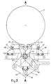
- Fig. 3 shows in a very schematic way a modified apparatus for manufacturing wheel rims according to the invention, in which in principle only the modified means for contracting and expanding the clamping band 2, which is shown out of scale, are illustrated. These means therefore replace the parts 4-9 in fig. 1.
- the means for contracting into a circle and expanding the clamping band include two fastening means 40, each of which has a respective free end of the clamping band 2 ridgidly attached thereto.
- Each fastening means 40 is clamped about a respective shaft 41, which is journalled on the upper end of a double-armed lever 42.
- Both levers 42 are symmetrically journalled on a shaft 43 and are connected on their lower ends by connecting means 44 of which the connecting shaft 45 is movable up and down in the vertical plane of symmetry A-A by means of a drive 46 for contracting and expanding the clamping band by moving the ends of this clamping band 2 towards and away from each other.
- the fastening means 40 are provided on their outer end facing away from the respective shaft 41 with a cam roller 47 adapted to roll on a respective cam 48.
- Each cam 48 is adjustably, preferably vertically adjustably, attached to the frame 1.
- the described parts of the means for contracting and expanding the clamping band 2 are arranged and dimensioned in such a way that the following operation is obtained.
- the fastening means 40 will undergo a movement depending from the displacement of the shaft 41 as well as from the displacement of the cam roller 47 over the respective cam 48.
- the profile of the cam 48 is chosen such that a movement of the free ends of the clamping band 2 is produced, which causes the upper point of the clamping band 2 to substantially remain stationary. As a consequence thereof the clamping band 2 could be suspended from a fixed point.
- the fastening means 40 is kept at the same angle with respect to the centre point of the clamping band 2, which moves in the vertical plane of symmetry.
- the clamping band 2 is expanded precisely circular and the fastening means 40 is not turned with respect to the end of the clamping band 2 connected therewith so that the fastening means 40 is prevented from exerting large bending forces on the connection to the end of the clamping band 2.
- the cams 48 can be adjusted in order to effect a movement of the fastening means 40 adapted to this other clamping band 2.
- each pair of dowel pins 49 belonging to one rim section to be manufactured is disposed in a separate holder 50.
- each holder 50 includes 2 grooves 51 extending transverse to the slide 39 and having magnets 52 placed under them.
- the holders 50 are attached to the slide 39 in a movable manner by means of a rod 53 of the slide 39 projecting through slack bores 54 in the holders 50.
- a spring means 55 between the slide 39 and the underside of the cam holder loads the respective holder 50 upwardly.
- each holder 50 Due to this mounting of the holders 50 they are slightly movable up and down and tiltable about the rod 53 independent of each other. As a consequence thereof the pairs of dowel pins 49 are enabled to be positioned well in front of the holes in the ends of the respective rim sections, also when these ends are clamped on different levels. To bring the pairs of dowel pins 49 automatically and properly in front of the holes in the rim ends, each holder 50 is equipped with locating tongues 56 extending oppositely in transverse direction and being dimensioned so as to fit precisely into the rim bed of a wheel rim to be manufactured.
- the dowel pins 49 are also automatically positioned in the right manner in front of the holes in those ends, wherein the resilient freedom of movement of the holders 50 allow an independent positioning of the holders. As a consequence thereof the apparatus can function even more reliable.
- the invention provides a method and apparatus for manufacturing wheel rims, in which from a spiral-shaped bent section piece can be formed a plurality of rims in a fully or almost fully automatic way.
- the spiral of the section piece includes preferably slightly more than three windings, so that at one time three rims can be made out of it, but in principle the number of windings of the spiral can be chosen freely.
Landscapes
- Engineering & Computer Science (AREA)
- Mechanical Engineering (AREA)
- Tyre Moulding (AREA)
- Sawing (AREA)
- Clamps And Clips (AREA)
Applications Claiming Priority (2)
| Application Number | Priority Date | Filing Date | Title |
|---|---|---|---|
| NL8902872 | 1989-11-21 | ||
| NL8902872A NL8902872A (nl) | 1989-11-21 | 1989-11-21 | Werkwijze en inrichting voor het vervaardigen van wielvelgen. |
Publications (2)
| Publication Number | Publication Date |
|---|---|
| EP0429104A1 true EP0429104A1 (de) | 1991-05-29 |
| EP0429104B1 EP0429104B1 (de) | 1993-06-09 |
Family
ID=19855664
Family Applications (1)
| Application Number | Title | Priority Date | Filing Date |
|---|---|---|---|
| EP19900202478 Expired - Lifetime EP0429104B1 (de) | 1989-11-21 | 1990-09-18 | Methode und Vorrichtung zur Herstellung von Radfelgen |
Country Status (3)
| Country | Link |
|---|---|
| EP (1) | EP0429104B1 (de) |
| DE (1) | DE69001887T2 (de) |
| NL (1) | NL8902872A (de) |
Cited By (2)
| Publication number | Priority date | Publication date | Assignee | Title |
|---|---|---|---|---|
| US5653510A (en) * | 1996-02-21 | 1997-08-05 | Syncros Applied Technology Incorporated | Wheel rims |
| CN114309157A (zh) * | 2021-12-27 | 2022-04-12 | 深圳市美大行科技有限公司 | 轮辋制造方法和轮辋制造装置 |
Citations (5)
| Publication number | Priority date | Publication date | Assignee | Title |
|---|---|---|---|---|
| BE493392A (de) * | ||||
| US1508570A (en) * | 1921-02-10 | 1924-09-16 | Acme Steel Goods Company | Hoop-making machine |
| FR1097211A (fr) * | 1953-04-02 | 1955-07-01 | Marocaine D Applic De Matiere | Perfectionnements aux jantes de bicyclettes ou produits analogues |
| US4164133A (en) * | 1975-11-21 | 1979-08-14 | Holland Mechanics B.V. | Apparatus for forming circularly bent articles from a straight metal profiled strip |
| US4365492A (en) * | 1980-06-25 | 1982-12-28 | Intercole Bolling Corp. | Ring former and cutoff |
-
1989
- 1989-11-21 NL NL8902872A patent/NL8902872A/nl not_active Application Discontinuation
-
1990
- 1990-09-18 DE DE1990601887 patent/DE69001887T2/de not_active Expired - Fee Related
- 1990-09-18 EP EP19900202478 patent/EP0429104B1/de not_active Expired - Lifetime
Patent Citations (5)
| Publication number | Priority date | Publication date | Assignee | Title |
|---|---|---|---|---|
| BE493392A (de) * | ||||
| US1508570A (en) * | 1921-02-10 | 1924-09-16 | Acme Steel Goods Company | Hoop-making machine |
| FR1097211A (fr) * | 1953-04-02 | 1955-07-01 | Marocaine D Applic De Matiere | Perfectionnements aux jantes de bicyclettes ou produits analogues |
| US4164133A (en) * | 1975-11-21 | 1979-08-14 | Holland Mechanics B.V. | Apparatus for forming circularly bent articles from a straight metal profiled strip |
| US4365492A (en) * | 1980-06-25 | 1982-12-28 | Intercole Bolling Corp. | Ring former and cutoff |
Cited By (3)
| Publication number | Priority date | Publication date | Assignee | Title |
|---|---|---|---|---|
| US5653510A (en) * | 1996-02-21 | 1997-08-05 | Syncros Applied Technology Incorporated | Wheel rims |
| CN114309157A (zh) * | 2021-12-27 | 2022-04-12 | 深圳市美大行科技有限公司 | 轮辋制造方法和轮辋制造装置 |
| CN114309157B (zh) * | 2021-12-27 | 2024-04-26 | 深圳市美大行科技有限公司 | 轮辋制造方法和轮辋制造装置 |
Also Published As
| Publication number | Publication date |
|---|---|
| NL8902872A (nl) | 1991-06-17 |
| DE69001887T2 (de) | 1994-02-03 |
| DE69001887D1 (de) | 1993-07-15 |
| EP0429104B1 (de) | 1993-06-09 |
Similar Documents
| Publication | Publication Date | Title |
|---|---|---|
| EP0039621A2 (de) | Verfahren und Vorrichtung zur Herstellung eines Reifens | |
| CN113042965A (zh) | 一种污水泵旋转焊接设备及其方法 | |
| EP0577176B1 (de) | Vorrichtung zum Formen von Schlachtgeflügel | |
| EP0429104B1 (de) | Methode und Vorrichtung zur Herstellung von Radfelgen | |
| EP1264681A1 (de) | Wulsthalter - Anordnung und Verfahren zum Halten und Positionieren eines Reifenwulstes | |
| EP1147980B1 (de) | Vorrichtung und Verfahren zum Verbinden von Verstärkungsrippen an eine Schale, insbesondere für ein Unterseeboot | |
| CA1272113A (en) | Method and device for automatically centering and feeding beads onto a tire building drum | |
| US20020174526A1 (en) | Apparatus for automated peening of tenons connecting turbine buckets and cover plates | |
| CN110449602A (zh) | 一种风力发电机转轴专用车床 | |
| CN110508669B (zh) | 轮辋气门冲孔装置 | |
| JP3904705B2 (ja) | 円形ワークの溶接装置 | |
| US4674701A (en) | Winding apparatus | |
| CN119665882A (zh) | 一种阀门齿轮箱齿轮生产用精度检测装置 | |
| US4674168A (en) | Method for exchanging the blade receivers in disc cutter machines and disc cutter machines for carrying out the method | |
| US4614485A (en) | Unloader for a tire curing machine | |
| CN119159647B (zh) | 一种全自动木材加工机 | |
| SU1479251A1 (ru) | Устройство дл сборки под сварку | |
| EP0142655A2 (de) | Vorrichtung zum Schleifen der Schweisszone von Radkränzen von Rädern von Fahrrädern und Kraftfahrzeugen | |
| CN115121986B (zh) | 一种椅腿焊接装置 | |
| EP0376405B1 (de) | Vorrichtung zum Positionieren von Reifenwülsten | |
| CN221209716U (zh) | 一种钢筋笼加工设备 | |
| CN219986859U (zh) | 一种涨紧器钻孔工装 | |
| CN224202422U (zh) | 一种天窗顶棚检具 | |
| CN117564753B (zh) | 一种锯条自动分齿机及其操作方法 | |
| CN215616258U (zh) | 一种两头压装设备 |
Legal Events
| Date | Code | Title | Description |
|---|---|---|---|
| PUAI | Public reference made under article 153(3) epc to a published international application that has entered the european phase |
Free format text: ORIGINAL CODE: 0009012 |
|
| 17P | Request for examination filed |
Effective date: 19901212 |
|
| AK | Designated contracting states |
Kind code of ref document: A1 Designated state(s): BE CH DE ES FR GB IT LI NL |
|
| 17Q | First examination report despatched |
Effective date: 19921125 |
|
| GRAA | (expected) grant |
Free format text: ORIGINAL CODE: 0009210 |
|
| AK | Designated contracting states |
Kind code of ref document: B1 Designated state(s): BE CH DE ES FR GB IT LI NL |
|
| PG25 | Lapsed in a contracting state [announced via postgrant information from national office to epo] |
Ref country code: ES Free format text: THE PATENT HAS BEEN ANNULLED BY A DECISION OF A NATIONAL AUTHORITY Effective date: 19930609 |
|
| REF | Corresponds to: |
Ref document number: 69001887 Country of ref document: DE Date of ref document: 19930715 |
|
| ITF | It: translation for a ep patent filed | ||
| ET | Fr: translation filed | ||
| PLBE | No opposition filed within time limit |
Free format text: ORIGINAL CODE: 0009261 |
|
| STAA | Information on the status of an ep patent application or granted ep patent |
Free format text: STATUS: NO OPPOSITION FILED WITHIN TIME LIMIT |
|
| 26N | No opposition filed | ||
| PG25 | Lapsed in a contracting state [announced via postgrant information from national office to epo] |
Ref country code: GB Effective date: 19940918 |
|
| GBPC | Gb: european patent ceased through non-payment of renewal fee |
Effective date: 19940918 |
|
| PGFP | Annual fee paid to national office [announced via postgrant information from national office to epo] |
Ref country code: CH Payment date: 19980901 Year of fee payment: 9 |
|
| PGFP | Annual fee paid to national office [announced via postgrant information from national office to epo] |
Ref country code: BE Payment date: 19980914 Year of fee payment: 9 |
|
| PG25 | Lapsed in a contracting state [announced via postgrant information from national office to epo] |
Ref country code: LI Free format text: LAPSE BECAUSE OF NON-PAYMENT OF DUE FEES Effective date: 19990930 Ref country code: CH Free format text: LAPSE BECAUSE OF NON-PAYMENT OF DUE FEES Effective date: 19990930 Ref country code: BE Free format text: LAPSE BECAUSE OF NON-PAYMENT OF DUE FEES Effective date: 19990930 |
|
| BERE | Be: lapsed |
Owner name: HOLLAND MECHANICS B.V. Effective date: 19990930 |
|
| REG | Reference to a national code |
Ref country code: CH Ref legal event code: PL |
|
| PGFP | Annual fee paid to national office [announced via postgrant information from national office to epo] |
Ref country code: NL Payment date: 20000925 Year of fee payment: 11 |
|
| PGFP | Annual fee paid to national office [announced via postgrant information from national office to epo] |
Ref country code: FR Payment date: 20000927 Year of fee payment: 11 |
|
| PGFP | Annual fee paid to national office [announced via postgrant information from national office to epo] |
Ref country code: DE Payment date: 20000929 Year of fee payment: 11 |
|
| PG25 | Lapsed in a contracting state [announced via postgrant information from national office to epo] |
Ref country code: NL Free format text: LAPSE BECAUSE OF NON-PAYMENT OF DUE FEES Effective date: 20020401 |
|
| PG25 | Lapsed in a contracting state [announced via postgrant information from national office to epo] |
Ref country code: DE Free format text: LAPSE BECAUSE OF NON-PAYMENT OF DUE FEES Effective date: 20020501 |
|
| PG25 | Lapsed in a contracting state [announced via postgrant information from national office to epo] |
Ref country code: FR Free format text: LAPSE BECAUSE OF NON-PAYMENT OF DUE FEES Effective date: 20020531 |
|
| NLV4 | Nl: lapsed or anulled due to non-payment of the annual fee |
Effective date: 20020401 |
|
| REG | Reference to a national code |
Ref country code: FR Ref legal event code: ST |
|
| NLV4 | Nl: lapsed or anulled due to non-payment of the annual fee |
Effective date: 20020401 |
|
| PG25 | Lapsed in a contracting state [announced via postgrant information from national office to epo] |
Ref country code: IT Free format text: LAPSE BECAUSE OF NON-PAYMENT OF DUE FEES Effective date: 20050918 |