EP0429111B1 - Filtre magnétique à barre - Google Patents
Filtre magnétique à barre Download PDFInfo
- Publication number
- EP0429111B1 EP0429111B1 EP90202831A EP90202831A EP0429111B1 EP 0429111 B1 EP0429111 B1 EP 0429111B1 EP 90202831 A EP90202831 A EP 90202831A EP 90202831 A EP90202831 A EP 90202831A EP 0429111 B1 EP0429111 B1 EP 0429111B1
- Authority
- EP
- European Patent Office
- Prior art keywords
- bars
- filter
- magnetic
- caracterised
- filter according
- Prior art date
- Legal status (The legal status is an assumption and is not a legal conclusion. Google has not performed a legal analysis and makes no representation as to the accuracy of the status listed.)
- Expired - Lifetime
Links
- 239000007788 liquid Substances 0.000 claims abstract description 21
- 239000000696 magnetic material Substances 0.000 claims abstract description 13
- 239000006249 magnetic particle Substances 0.000 claims abstract description 12
- 238000001914 filtration Methods 0.000 claims description 2
- HCHKCACWOHOZIP-UHFFFAOYSA-N Zinc Chemical compound [Zn] HCHKCACWOHOZIP-UHFFFAOYSA-N 0.000 claims 1
- 239000003822 epoxy resin Substances 0.000 claims 1
- 229920000647 polyepoxide Polymers 0.000 claims 1
- 239000011701 zinc Substances 0.000 claims 1
- 229910052725 zinc Inorganic materials 0.000 claims 1
- 239000002245 particle Substances 0.000 abstract description 10
- 229910019142 PO4 Inorganic materials 0.000 abstract description 4
- 238000011010 flushing procedure Methods 0.000 abstract description 4
- 235000021317 phosphate Nutrition 0.000 abstract description 4
- 150000003013 phosphoric acid derivatives Chemical class 0.000 abstract description 4
- SZVJSHCCFOBDDC-UHFFFAOYSA-N iron(II,III) oxide Inorganic materials O=[Fe]O[Fe]O[Fe]=O SZVJSHCCFOBDDC-UHFFFAOYSA-N 0.000 abstract description 2
- 239000002351 wastewater Substances 0.000 abstract description 2
- 238000003491 array Methods 0.000 description 4
- 230000008878 coupling Effects 0.000 description 4
- 238000010168 coupling process Methods 0.000 description 4
- 238000005859 coupling reaction Methods 0.000 description 4
- 238000004804 winding Methods 0.000 description 3
- 238000004140 cleaning Methods 0.000 description 1
- 229910052500 inorganic mineral Inorganic materials 0.000 description 1
- 238000007689 inspection Methods 0.000 description 1
- 230000005389 magnetism Effects 0.000 description 1
- 238000000034 method Methods 0.000 description 1
- 239000011707 mineral Substances 0.000 description 1
- 239000007787 solid Substances 0.000 description 1
- 239000011882 ultra-fine particle Substances 0.000 description 1
Images

Classifications
-
- B—PERFORMING OPERATIONS; TRANSPORTING
- B03—SEPARATION OF SOLID MATERIALS USING LIQUIDS OR USING PNEUMATIC TABLES OR JIGS; MAGNETIC OR ELECTROSTATIC SEPARATION OF SOLID MATERIALS FROM SOLID MATERIALS OR FLUIDS; SEPARATION BY HIGH-VOLTAGE ELECTRIC FIELDS
- B03C—MAGNETIC OR ELECTROSTATIC SEPARATION OF SOLID MATERIALS FROM SOLID MATERIALS OR FLUIDS; SEPARATION BY HIGH-VOLTAGE ELECTRIC FIELDS
- B03C1/00—Magnetic separation
- B03C1/02—Magnetic separation acting directly on the substance being separated
- B03C1/025—High gradient magnetic separators
- B03C1/031—Component parts; Auxiliary operations
- B03C1/033—Component parts; Auxiliary operations characterised by the magnetic circuit
- B03C1/034—Component parts; Auxiliary operations characterised by the magnetic circuit characterised by the matrix elements
Definitions
- the present invention relates to a filter for filtering magnetic particles from a flowing liquid, the filter comprising:
- Such bar filters are applied in apparatuses, in which a liquid, in which magnetic particles have been suspended is filtered for removing the magnetic particles from the liquid.
- phosphates are chemically bond to magnetic material, for instance magnetite, after which the liquid thus obtained is fed through a filter according to the present invention.
- the phosphatemagnetite particles adhere to the bars of the magnetic filter, in which the filter is increasingly filled with these particles, which have to be removed from the liquid.
- the filter is filled to such extent, that the passage thereof is limited considerably. Then the filter has to be cleaned.
- the aim of the present invention is to provide such a filter, in which the filling of the filter is as much homogeneous as possible.
- the chamber has the shape of a cylinder jacket, that the bars are parallel to the axis of the cylinder, and that the direction of the magnetic field is radial, in which the product of the distance between two bars subsequent in radial direction and the mean distance between said bars and the axis is constant.
- JP-A-6274460 discloses a magnetic filter of a rectangular configuration and which is constructed for collecting ultrafine particles.
- SU-A-925394 discloses a magnetic filter of a cylindrical configuration, and in which the magnetic field appears to be parallel with the direction of flow.
- the apparatus depicted in fig. 1 comprises a chamber 1, in which a number of bars 2 extending in a vertical direction has been provided. These bars are mutually connected at their upper and lower sides respectively by means of strips 3 of non-magnetic material. The distance between a adjacent bars in the direction of the field lines is constant, so that the gradient of the magnetic field is equal. Also the distance between adjacent bars in the direction perpendicular to the field direction is equal, so that the room to be filled is equal. Further a supply pipe 4 has been provided, which is connected with the chamber 1 by means of a widening coupling piece 5. Above the chamber 1 a second coupling piece 6 has been provided, leading to a drain pipe 7.
- a magnetic circuit connected with two opposite sides of the chamber 1 which circuit comprises a yoke 8 of magnetic material, around which a winding 9 has been wound.
- a liquid comprising magnetic particle suspended therein is supplied from below through the supply line 4, after which the liquid is fed to the chamber 1 by means of the coupling piece 5, and is drained via the coupling piece 6 and the drain pipe 7. Further a current is applied to the winding 9, so that a magnetic field 10 will develop in the yoke 8.
- the direction of the magnetic field is indicated by dotted lines 10.
- the field will also extend through the chamber 1, and therein it will be guided substantially through the bars 2, such that the field extends in a beadlike way between two subsequent bars.
- the equal distance between the bars, coinciding with several times the diameters of the bars is of importance.
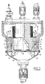
- FIG. 2 shows another embodiment of the filter according to the present invention as applied in an apparatus as known from the Dutch patent application 88.01463.
- the annular filter 9 that, in the case of said patent application, is manufactured from a magnetisable grate with small meshes replaced by the rod filter as described in the present application.
- the rod filter has been provided in the space between the outer wall 11 of the apparatus and the core 12.
- the rod filter 13 comprises three arrays of bars each arranged in the shape of a circle, which have been mutually connected in the radial direction between bars 16 of non-magnetic material.
- the arrays of bars are welded to concentric hoops 17, 18 respectively and at their lower sides to hoops 19, 20 respectively.
- the hoops do not have to be made of non-magnetic material. Further the hoops are mutually connected by means of non-magnetic strips 21.
- the hoops 17, 18, 19, 20 can be interrupted to devide the filter into segments, so that the segments can be removed piece by piece from the magnetic housing, just as is the case in the embodiment according to fig. 5 still to be described.
- the inner hoopes 20 comprise support 22, through which the whole filter rests against support 24 provided at the inner side of the lower piece 23.
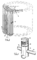
- Fig. 3 shows another embodiment of the annular filter, which diverges from the embodiment shown in fig. 2 only by the number of rods; in the embodiment according to fig. 3 bars arranged according to four circles have been provided, whereas in the embodiment according to fig. 2 only three circles of rods have been provided.
- hollow rods or pipes 25 have been applied, which are mutually connected in the radial direction by means of solid rods 26.
- the filter rods 25 are provided of layer of non-magnetic material. Halfway the rods are mutually connected in the radial direction by strips 27, which have been provided of non-magnetic material.
- This filter can be applied in the same way as the filter as depicted in fig. 3.
- every pipe 25 is surrounded by a layer 28 of non-magnetic material. This provides the action as set out in the preamble of the present application.
- caps 29 At the upper side, just as at the lower side of every pipe 25 caps 29 have been provided to avoid the liquid entering the inner place of the pipes.
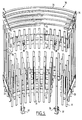
- Fig. 5 shows an embodiment, which can be applied to the apparatus shown in fig. 2, and which the bar filter has been devided into segments 30 to ease the removal from the filter, for instance for inspection.
- Fig. 5 shows such a segment 30.
- the distances between the bars and the radial direction are such, that the product of the mean distance between two bars and the centre and the distance between these two adjacent bars is constant. Further the distances between the bars in the tangential direction within an array are constant, whereas the distances per array increase, as the total number of rods in every circle is equal and the circumference of the circle is increasing.
- the bars 34 have been provided in two layers, of which the lower layer is located between the imaginary extension of the bars 31.
- This provides an improved catching of magnetic particles obtained by the particles which move in the direction of flow in the middle between two bars 31 by means of the lower bar 34.
- the upper layer of bars serves as a last possibility for the particles which have not used the first catching possibilities.
- rate of catching of the filter is substantially improved.
Landscapes
- Water Treatment By Electricity Or Magnetism (AREA)
- Color Television Image Signal Generators (AREA)
- Magnetic Resonance Imaging Apparatus (AREA)
- Thermistors And Varistors (AREA)
- Filtering Materials (AREA)
- Solid-Sorbent Or Filter-Aiding Compositions (AREA)
Claims (10)
- Filtre pour filtrer des particules magnétiques contenues dans un liquide en circulation, le filtre comprenant :- une chambre, dans laquelle est introduit le liquide à filtrer ;- des barres montées parallèlement à la direction d'écoulement du liquide dans la chambre ; et- des moyens pour appliquer un champ magnétique perpendiculaire aux barres ;caractérisé en ce que la chambre a la forme d'une enveloppe cylindrique, en ce que les barres sont parallèles à l'axe du cylindre, et en ce que la direction du champ magnétique est radiale, et dans lequel le produit de la distance entre deux barres successives, dans la direction radiale, par la distance moyenne entre lesdits barres et l'axe, est constant.
- Filtre selon la revendication 1, caractérisé en ce que les barres ont reçu une couche de matériau non magnétique.
- Filtre selon la revendication 2, caractérisé en ce que la couche de matériau non magnétique est en une résine époxy.
- Filtre selon la revendication 2, caractérisé en ce que la couche de matériau non magnétique est en zinc.
- Filtre selon l'une des revendications 2 à 4, caractérisé en ce que la distance entre les barres est égale à plusieurs fois le diamètre des barres.
- Filtre selon la revendication 5, caractérisé en ce que la distance entre les barres est comprise entre 2 et 5 fois le diamètre des barres.
- Filtre selon l'une des revendications précédentes, caractérisé en ce que les barres sont creuses.
- Filtre selon l'une des revendications précédentes, caractérisé en ce que, derrière le filtre, est monté un second filtre dont les barres sont perpendiculaires à la direction de l'écoulement et à la direction du champ magnétique.
- Filtre selon la revendication 8, caractérisé en ce qu'au moins une partie des barres du second filtre sont placées à mi-chemin entre les saillies des barres du filtre principal.
- Filtre selon la revendication 9, caractérisé en ce qu'au moins une partie des barres du second filtre est dans le prolongement des barres du filtre principal.
Applications Claiming Priority (2)
| Application Number | Priority Date | Filing Date | Title |
|---|---|---|---|
| NL8902878 | 1989-11-21 | ||
| NL8902878A NL8902878A (nl) | 1989-11-21 | 1989-11-21 | Stavenfilter. |
Publications (2)
| Publication Number | Publication Date |
|---|---|
| EP0429111A1 EP0429111A1 (fr) | 1991-05-29 |
| EP0429111B1 true EP0429111B1 (fr) | 1994-05-18 |
Family
ID=19855667
Family Applications (1)
| Application Number | Title | Priority Date | Filing Date |
|---|---|---|---|
| EP90202831A Expired - Lifetime EP0429111B1 (fr) | 1989-11-21 | 1990-10-23 | Filtre magnétique à barre |
Country Status (5)
| Country | Link |
|---|---|
| US (1) | US5122269A (fr) |
| EP (1) | EP0429111B1 (fr) |
| AT (1) | ATE105737T1 (fr) |
| DE (1) | DE69009008T2 (fr) |
| NL (1) | NL8902878A (fr) |
Families Citing this family (9)
| Publication number | Priority date | Publication date | Assignee | Title |
|---|---|---|---|---|
| US5514283A (en) * | 1990-07-11 | 1996-05-07 | Stefanini; Daniel | Arrangement for and method of treating fluid |
| US5858223A (en) * | 1991-03-25 | 1999-01-12 | Carpco, Inc. | Magnetic separators |
| US5540089A (en) * | 1994-03-17 | 1996-07-30 | Diagnetics, Inc. | Ferrous particle collection apparatus |
| US5708198A (en) * | 1994-03-17 | 1998-01-13 | Diagnetics, Inc. | Ferrous particle counter |
| US7364921B1 (en) | 1999-01-06 | 2008-04-29 | University Of Medicine And Dentistry Of New Jersey | Method and apparatus for separating biological materials and other substances |
| ES2264899B1 (es) | 2005-07-12 | 2008-01-01 | Centro De Investigacion De Rotacion Y Torque Aplicada, S.L. | Filtro para capturar emisiones contaminantes. |
| US7969096B2 (en) * | 2006-12-15 | 2011-06-28 | Mks Instruments, Inc. | Inductively-coupled plasma source |
| EP2067526A1 (fr) | 2007-11-29 | 2009-06-10 | Corning Incorporated | Dispositifs et procédés de traitement chimique assisté par rayonnement |
| ES2567300B1 (es) * | 2014-10-20 | 2017-02-13 | Gaston OLEA AMOR | Matriz para la separación magnética en fluidos |
Family Cites Families (8)
| Publication number | Priority date | Publication date | Assignee | Title |
|---|---|---|---|---|
| DE58797C (de) * | W. B. BULL in Quincy, Grfsch. Adams, Illinois, V. St. A | Vorrichtung zum Abscheiden von Verunreinigungen aus nicht alkoholhaltigen Flüssigkeiten | ||
| US2094616A (en) * | 1936-09-24 | 1937-10-05 | Joseph E Parker | Apparatus for recovery of black or other magnetic sands or silts from streams |
| US3143496A (en) * | 1962-02-08 | 1964-08-04 | Cons Edison Co New York Inc | Magnetic filter apparatus and method |
| SU925394A1 (ru) * | 1979-01-22 | 1982-05-07 | Предприятие П/Я Р-6603 | Электромагнитный аппарат |
| JPS6274460A (ja) * | 1985-09-30 | 1987-04-06 | Hitachi Ltd | 超微粒子の捕集装置 |
| JPS634819A (ja) * | 1986-06-25 | 1988-01-09 | Nippon Steel Corp | 磁気分離フイルター材料 |
| JPS634818A (ja) * | 1986-06-25 | 1988-01-09 | Nippon Steel Corp | 磁気分離フイルタ−材料 |
| NL8801463A (nl) * | 1988-06-07 | 1990-01-02 | Smit Transformatoren Bv | Magnetische separatie-inrichting. |
-
1989
- 1989-11-21 NL NL8902878A patent/NL8902878A/nl not_active Application Discontinuation
-
1990
- 1990-10-23 AT AT90202831T patent/ATE105737T1/de not_active IP Right Cessation
- 1990-10-23 EP EP90202831A patent/EP0429111B1/fr not_active Expired - Lifetime
- 1990-10-23 DE DE69009008T patent/DE69009008T2/de not_active Expired - Fee Related
- 1990-11-19 US US07/615,607 patent/US5122269A/en not_active Expired - Fee Related
Also Published As
| Publication number | Publication date |
|---|---|
| EP0429111A1 (fr) | 1991-05-29 |
| US5122269A (en) | 1992-06-16 |
| DE69009008D1 (de) | 1994-06-23 |
| ATE105737T1 (de) | 1994-06-15 |
| NL8902878A (nl) | 1991-06-17 |
| DE69009008T2 (de) | 1994-09-08 |
Similar Documents
| Publication | Publication Date | Title |
|---|---|---|
| US10010891B2 (en) | Magnetic filter | |
| EP0429111B1 (fr) | Filtre magnétique à barre | |
| EP0082925B1 (fr) | Séparateur magnétique | |
| WO1999058247A1 (fr) | Systeme de filtration magnetique | |
| SU1069608A3 (ru) | Устройство дл сепарации магнитных частиц | |
| GB1578396A (en) | Magnetic separator | |
| CN205236166U (zh) | 免拆洗浆料高梯度磁选机 | |
| CA2743364C (fr) | Dispositif pour le depot de particules ferromagnetiques a partir d'une suspension | |
| JPS621425A (ja) | 濾過脱塩装置 | |
| NL8801463A (nl) | Magnetische separatie-inrichting. | |
| JPS6242647B2 (fr) | ||
| KR20190011779A (ko) | 유체를 위한 필터 디바이스 | |
| US4303504A (en) | Magnetic filtration | |
| CA1158567A (fr) | Filtre electromagnetique a bobine amovible | |
| US4356093A (en) | Method of increasing the effectiveness of or the effective production rate of a process by integrated feed | |
| EP0429700B1 (fr) | Dispositif pour la purification continue des liquides, en particulier de l'eau, par la filtration magnétique à haut gradient | |
| KR101064533B1 (ko) | 필터 요소 | |
| CN221333044U (zh) | 利用电磁场控制磁性颗粒的可调孔径易反冲洗滤网滤床 | |
| KR20140147330A (ko) | 경사나선식 섬유여재 고정판 및 이를 이용하는 섬유여과기 | |
| JPS61271043A (ja) | 磁気フイルタ− | |
| SU1156739A1 (ru) | Электромагнитный сепаратор | |
| RU2190453C1 (ru) | Высокоградиентный магнитный фильтр | |
| JPS60100Y2 (ja) | 電磁濾過機 | |
| GB2057918A (en) | Magnetic filtration | |
| JPS6156008B2 (fr) |
Legal Events
| Date | Code | Title | Description |
|---|---|---|---|
| PUAI | Public reference made under article 153(3) epc to a published international application that has entered the european phase |
Free format text: ORIGINAL CODE: 0009012 |
|
| AK | Designated contracting states |
Kind code of ref document: A1 Designated state(s): AT BE CH DE DK ES FR GB IT LI NL SE |
|
| 17P | Request for examination filed |
Effective date: 19910926 |
|
| RAP1 | Party data changed (applicant data changed or rights of an application transferred) |
Owner name: ENVIMAG B.V. |
|
| 17Q | First examination report despatched |
Effective date: 19921028 |
|
| GRAA | (expected) grant |
Free format text: ORIGINAL CODE: 0009210 |
|
| AK | Designated contracting states |
Kind code of ref document: B1 Designated state(s): AT BE CH DE DK ES FR GB IT LI NL SE |
|
| PG25 | Lapsed in a contracting state [announced via postgrant information from national office to epo] |
Ref country code: IT Free format text: LAPSE BECAUSE OF FAILURE TO SUBMIT A TRANSLATION OF THE DESCRIPTION OR TO PAY THE FEE WITHIN THE PRE;WARNING: LAPSES OF ITALIAN PATENTS WITH EFFECTIVE DATE BEFORE 2007 MAY HAVE OCCURRED AT ANY TIME BEFORE 2007. THE CORRECT EFFECTIVE DATE MAY BE DIFFERENT FROM THE ONE RECORDED.SCRIBED TIME-LIMIT Effective date: 19940518 Ref country code: LI Effective date: 19940518 Ref country code: SE Free format text: THE PATENT HAS BEEN ANNULLED BY A DECISION OF A NATIONAL AUTHORITY Effective date: 19940518 Ref country code: DK Effective date: 19940518 Ref country code: ES Free format text: THE PATENT HAS BEEN ANNULLED BY A DECISION OF A NATIONAL AUTHORITY Effective date: 19940518 Ref country code: AT Effective date: 19940518 Ref country code: CH Effective date: 19940518 Ref country code: BE Effective date: 19940518 |
|
| REF | Corresponds to: |
Ref document number: 105737 Country of ref document: AT Date of ref document: 19940615 Kind code of ref document: T |
|
| REF | Corresponds to: |
Ref document number: 69009008 Country of ref document: DE Date of ref document: 19940623 |
|
| ET | Fr: translation filed | ||
| REG | Reference to a national code |
Ref country code: CH Ref legal event code: PL |
|
| PLBE | No opposition filed within time limit |
Free format text: ORIGINAL CODE: 0009261 |
|
| STAA | Information on the status of an ep patent application or granted ep patent |
Free format text: STATUS: NO OPPOSITION FILED WITHIN TIME LIMIT |
|
| 26N | No opposition filed | ||
| PGFP | Annual fee paid to national office [announced via postgrant information from national office to epo] |
Ref country code: GB Payment date: 19951004 Year of fee payment: 6 |
|
| PGFP | Annual fee paid to national office [announced via postgrant information from national office to epo] |
Ref country code: FR Payment date: 19951027 Year of fee payment: 6 |
|
| PGFP | Annual fee paid to national office [announced via postgrant information from national office to epo] |
Ref country code: DE Payment date: 19951031 Year of fee payment: 6 Ref country code: NL Payment date: 19951031 Year of fee payment: 6 |
|
| PG25 | Lapsed in a contracting state [announced via postgrant information from national office to epo] |
Ref country code: GB Effective date: 19961023 |
|
| PG25 | Lapsed in a contracting state [announced via postgrant information from national office to epo] |
Ref country code: NL Effective date: 19970501 |
|
| GBPC | Gb: european patent ceased through non-payment of renewal fee |
Effective date: 19961023 |
|
| PG25 | Lapsed in a contracting state [announced via postgrant information from national office to epo] |
Ref country code: FR Effective date: 19970630 |
|
| NLV4 | Nl: lapsed or anulled due to non-payment of the annual fee |
Effective date: 19970501 |
|
| PG25 | Lapsed in a contracting state [announced via postgrant information from national office to epo] |
Ref country code: DE Effective date: 19970701 |
|
| REG | Reference to a national code |
Ref country code: FR Ref legal event code: ST |