EP0429220B1 - Verfahren zur Kodierung einer binären Datenfolge - Google Patents
Verfahren zur Kodierung einer binären Datenfolge Download PDFInfo
- Publication number
- EP0429220B1 EP0429220B1 EP19900312196 EP90312196A EP0429220B1 EP 0429220 B1 EP0429220 B1 EP 0429220B1 EP 19900312196 EP19900312196 EP 19900312196 EP 90312196 A EP90312196 A EP 90312196A EP 0429220 B1 EP0429220 B1 EP 0429220B1
- Authority
- EP
- European Patent Office
- Prior art keywords
- state
- codewords
- binary data
- data byte
- channel
- Prior art date
- Legal status (The legal status is an assumption and is not a legal conclusion. Google has not performed a legal analysis and makes no representation as to the accuracy of the status listed.)
- Expired - Lifetime
Links
- 238000000034 method Methods 0.000 title claims description 26
- 230000000295 complement effect Effects 0.000 claims description 14
- 238000010586 diagram Methods 0.000 claims description 14
- 230000004044 response Effects 0.000 claims description 14
- 230000003595 spectral effect Effects 0.000 claims description 14
- 230000010363 phase shift Effects 0.000 claims description 5
- 238000001228 spectrum Methods 0.000 claims description 5
- 230000006870 function Effects 0.000 description 4
- 238000007476 Maximum Likelihood Methods 0.000 description 3
- 238000007796 conventional method Methods 0.000 description 1
- 230000007423 decrease Effects 0.000 description 1
- 230000003247 decreasing effect Effects 0.000 description 1
- 230000001934 delay Effects 0.000 description 1
- 230000003111 delayed effect Effects 0.000 description 1
- 230000001419 dependent effect Effects 0.000 description 1
- 238000001514 detection method Methods 0.000 description 1
- 230000008030 elimination Effects 0.000 description 1
- 238000003379 elimination reaction Methods 0.000 description 1
- 230000003287 optical effect Effects 0.000 description 1
- 230000007704 transition Effects 0.000 description 1
Images

Classifications
-
- G—PHYSICS
- G11—INFORMATION STORAGE
- G11B—INFORMATION STORAGE BASED ON RELATIVE MOVEMENT BETWEEN RECORD CARRIER AND TRANSDUCER
- G11B20/00—Signal processing not specific to the method of recording or reproducing; Circuits therefor
- G11B20/10—Digital recording or reproducing
- G11B20/10009—Improvement or modification of read or write signals
- G11B20/10046—Improvement or modification of read or write signals filtering or equalising, e.g. setting the tap weights of an FIR filter
- G11B20/10055—Improvement or modification of read or write signals filtering or equalising, e.g. setting the tap weights of an FIR filter using partial response filtering when writing the signal to the medium or reading it therefrom
-
- G—PHYSICS
- G11—INFORMATION STORAGE
- G11B—INFORMATION STORAGE BASED ON RELATIVE MOVEMENT BETWEEN RECORD CARRIER AND TRANSDUCER
- G11B20/00—Signal processing not specific to the method of recording or reproducing; Circuits therefor
- G11B20/10—Digital recording or reproducing
- G11B20/10009—Improvement or modification of read or write signals
-
- G—PHYSICS
- G11—INFORMATION STORAGE
- G11B—INFORMATION STORAGE BASED ON RELATIVE MOVEMENT BETWEEN RECORD CARRIER AND TRANSDUCER
- G11B20/00—Signal processing not specific to the method of recording or reproducing; Circuits therefor
- G11B20/10—Digital recording or reproducing
- G11B20/14—Digital recording or reproducing using self-clocking codes
- G11B20/1403—Digital recording or reproducing using self-clocking codes characterised by the use of two levels
- G11B20/1423—Code representation depending on subsequent bits, e.g. delay modulation, double density code, Miller code
- G11B20/1426—Code representation depending on subsequent bits, e.g. delay modulation, double density code, Miller code conversion to or from block codes or representations thereof
-
- H—ELECTRICITY
- H03—ELECTRONIC CIRCUITRY
- H03M—CODING; DECODING; CODE CONVERSION IN GENERAL
- H03M13/00—Coding, decoding or code conversion, for error detection or error correction; Coding theory basic assumptions; Coding bounds; Error probability evaluation methods; Channel models; Simulation or testing of codes
- H03M13/31—Coding, decoding or code conversion, for error detection or error correction; Coding theory basic assumptions; Coding bounds; Error probability evaluation methods; Channel models; Simulation or testing of codes combining coding for error detection or correction and efficient use of the spectrum
-
- H—ELECTRICITY
- H04—ELECTRIC COMMUNICATION TECHNIQUE
- H04L—TRANSMISSION OF DIGITAL INFORMATION, e.g. TELEGRAPHIC COMMUNICATION
- H04L25/00—Baseband systems
- H04L25/38—Synchronous or start-stop systems, e.g. for Baudot code
- H04L25/40—Transmitting circuits; Receiving circuits
- H04L25/49—Transmitting circuits; Receiving circuits using code conversion at the transmitter; using predistortion; using insertion of idle bits for obtaining a desired frequency spectrum; using three or more amplitude levels ; Baseband coding techniques specific to data transmission systems
- H04L25/4906—Transmitting circuits; Receiving circuits using code conversion at the transmitter; using predistortion; using insertion of idle bits for obtaining a desired frequency spectrum; using three or more amplitude levels ; Baseband coding techniques specific to data transmission systems using binary codes
- H04L25/4908—Transmitting circuits; Receiving circuits using code conversion at the transmitter; using predistortion; using insertion of idle bits for obtaining a desired frequency spectrum; using three or more amplitude levels ; Baseband coding techniques specific to data transmission systems using binary codes using mBnB codes
-
- G—PHYSICS
- G11—INFORMATION STORAGE
- G11B—INFORMATION STORAGE BASED ON RELATIVE MOVEMENT BETWEEN RECORD CARRIER AND TRANSDUCER
- G11B20/00—Signal processing not specific to the method of recording or reproducing; Circuits therefor
- G11B20/10—Digital recording or reproducing
- G11B20/14—Digital recording or reproducing using self-clocking codes
- G11B20/1403—Digital recording or reproducing using self-clocking codes characterised by the use of two levels
- G11B20/1423—Code representation depending on subsequent bits, e.g. delay modulation, double density code, Miller code
- G11B20/1426—Code representation depending on subsequent bits, e.g. delay modulation, double density code, Miller code conversion to or from block codes or representations thereof
- G11B2020/1438—8 to 10 modulation
Definitions
- This invention relates to a method of coding input strings of binary data over partial-response channels using maximum-likelihood sequence detection (PRML). More particularly, it relates to a method employing an improved rate 8/10 matched spectral null trellis code for PRML channels which provides block decoding, phase reversal invariance, decreased encoder/decoder complexity, and elimination of quasi-catastrophic sequences, while maintaining high coding gain.
- PRML maximum-likelihood sequence detection
- GB 2099263-A describes a coding system in which each data word is assigned a set of codewords, each set comprising two or four words. Half the words in a set start with a binary "0", the others with a binary "1". The particular codeword that is selected from the set commences with the same bit as the last bit of the immediately preceding codeword.
- MSN matched spectral null
- the invention provides a method for coding a binary data string for a partial-response channel having a transfer function with a spectral null at zero frequency to provide a code which is invariant to 180-degree phase shifts in the channel output signal and which may be decoded using a trellis decoder, said coding being performed using a finite-state machine having a plurality of pairs of states, with states in the same pair being termed complementary states, and a plurality of codewords each corresponding to a respective binary data byte, said method comprising the steps of:
- decoding is performed by a block decoder requiring no look-ahead to decode, and the code does not employ any quasi-catastrophic sequences from a spectrul null canonical state diagram.
- the method further comprises the step of preselecting the next state of said machine according to the value of the data byte and the current state.
- a binary data string is coded for a partial-response channel having a transfer function with a spectral null at zero frequency to provide a coding rate and an output which is invariant to 180-degree phase shifts in the channel output signal.
- a finite-state machine is created having a plurality of pairs of states and a plurality of codewords each corresponding to a respective binary data byte.
- the binary data string is encoded by said machine into a string of binary codewords having a power spectrum value of zero for a frequency of zero.
- one of two complementary codewords is generated from said binary codeword string.
- the said one complementary codeword is so decoded as to provide the same data byte output irrespective of which of said complementary codewords was generated.
- the next state of said machine is preselected according to the value of the data byte and current state, and the next state for one element of a pair is the complement of the next state for the other element of the same pair.
- a high rate 8/10 MSN trellis code for a partial response channel such as a dicode (1-D) partial-response channel.
- the code can also be adapted to a class 4 (1-D 2 ) partial-response channel by interleaving using the technique disclosed, for example, in the December 1988 issue of the IBM Technical Disclosure Bulletin at pp. 476 et seq. These are among the codes of greatest current interest in magnetic and optical data recording.
- an MSN trellis code spectrum is designed to have nulls at frequencies where the channel transfer function has a null, thereby providing improved coding gains and reduced Viterbi decoder complexity.
- input data such as in the form of binary symbol strings, is transmitted from a bus 10 to a rate 8/10 finite-state-machine encoder 11.
- Encoder 11 produces a binary code symbol sequence that serves as input to a dicode (1-D) partial-response channel 12.
- This code has a power spectrum of zero for each frequency at which there is a zero in the transfer function of channel 12; i.e., the code sequences have spectral nulls that match those of the partial-response channel.
- a channel output sequence is generated by partial-response channel 12 and detected at the channel output by a Viterbi detector 13. This detector calculates the most probable code sequence from the channel output sequence.
- Detector 13 reduces computational and hardware requirements by tracking only the frequency spectral content of the channel output sequence, thereby producing a near maximum-likelihood estimate (or most probable code sequence) of the transmitted original data sequence supplied by the bus 10.
- a rate 10/8 decoder 14 then generates from the detected sequence the MSN code output data in a bus 15.
- Table 1 shows the structure of the finite-state-machine encoder 11.
- the encoder 11 has four states designated by decimal numbers (0-3), and divided into two pairs 0,3 and 1,2. Within each pair, a given data byte will produce one of two complementary codewords, dependent upon which of the pair of states is the current state of the encoder. Data words are denoted by decimal numbers (0-255). Codewords are grouped into lists with similar properties (as hereinafter described) and designated by capital letters, with the size of the set indicated in parentheses. For example, F(10) denotes a list of 10 codewords (124, 188, 220, 236, 241, 242, 244, 248, 316 and 451, in decimal) designated by F.
- the notation F ⁇ denotes the list of codewords which are obtained from the words in set F by bitwise complementing.
- Table 1 Finite-State-Machine Encoder Structure State Data Next Codeword 0 0 - 99 3 A(100) 0 100 - 142 2 B( 43) 0 143 - 255 2 C(113) 1 0 - 9 2 F( 10) 1 10 - 99 2 D( 90) 1 100 - 142 0 E( 43) 1 143 - 255 0 C ⁇ (113) 2 0 - 9 1 F ⁇ ( 10) 2 10 - 99 1 D ⁇ ( 90) 2 100 - 142 3 E ⁇ ( 43) 2 143 - 255 3 C(113) 3 0 - 99 0 A ⁇ (100) 3 100 - 142 1 B ⁇ ( 43) 3 143 - 255 1 C ⁇ (113) 3 0 - 99 0 A ⁇ (100) 3 100 - 142 1 B ⁇ ( 43
- the states are labelled 1 through 7.
- the paths in the diagram generate all binary sequences with digital sum variation (DSV) bounded by 6.
- Fig. 3 The component of the second power of the diagram of Fig. 2, which contains states 2, 4 and 6, is shown in Fig. 3.
- the edges in Fig. 3 correspond to pairs of edges in Fig. 2 and are labelled by pairs of binary symbols.
- the lists of codewords used in the finite-state-machine encoder 11 are best described in terms of the diagram in Fig. 3.
- Fig. 3 is used to derive the Viterbi detector trellis structure illustrated in Fig. 5. All codewords are 10 bits in length and are generated by paths of length 5 in Fig. 3.
- Table 2 gives a full description of the codeword lists, with the 10-bit words expressed in decimal. Lists are ordered left-to-right, row-by-row from top-to-bottom.
- rate 8/10 code described herein does not employ any of the quasi-catastrophic sequences of the canonical state diagram.
- Fig. 4 illustrates a read only memory (ROM) implementation of finite-state-machine encoder 11 for the rate 8/10 trellis code.
- the ROM contents are derived directly from the right-most two columns of the finite-state-machine encoder Table 1.
- Encoder 11, as illustrated, comprises registers 20,21 and a ROM 22.
- the 8-bit input data string is delayed one machine cycle by register 20 and then output to ROM 22.
- ROM 22 also receives a 2-bit input from register 21, which constitutes the current state of encoder 11.
- the output from ROM 22 is a 10-bit codeword, 2 bits of which are recirculated via register 21 for denoting the next state.
- Encoder 11 generates a binary code sequence that is input to the dicode partial-response channel 12.
- the output sequence generated by channel 12, affected by noise, is detected by Viterbi detector 13.
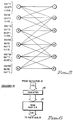
- Fig. 5 shows the reduced complexity trellis structure of Viterbi detector 13 for the rate 8/10 MSN trellis code.
- Detector 13 is similar to that described in the above-cited copending application. It calculates most probable code sequence from the output sequence of channel 12. Detector 13 reduces computational and hardware requirements by tracking only the frequency spectral content of the channel output sequence, thereby to produce a near maximum-likelihood estimate (or most probable code sequence) of the original data sequence supplied via bus 10.
- the trellis is derived from the diagram in Fig. 3, and represents the possible sequences at the output of dicode channel 12 when the channel inputs are generated by Fig. 3.
- the edges are labelled by u 1 u 2 /v 1 v 2 where u 1 u 2 are code symbols and v 1 v 2 are channel output symbols.
- the Viterbi algorithm for the trellis in Fig. 5 is derived according to conventional methods such as described in the March 1973 issue of IEEE Proceedings at pp. 268-278.
- the survivor metric update rules are given in detail in Table 3.
- Survivor path extensions are determined on the basis of the metric update computation in the usual manner (Add-Compare-Select).
- M n (j) is the survivor metric for state j at time n, where j varies from 1 to 6; and 3 1 and 3 2 represent two consecutive output signals from the channel.
- the rate 8/10 code is decoded with block decoder 14 that provides an output (see Table 4) which is the same for a codeword or its complement. Decoder 14 generates, from the detected sequence, the MSN code output data which is transmitted to bus 15.
- Decoder 14 requires no look-ahead to decode the current codeword. For the current 10-bit codeword y , decoder 14 determines an 8-bit word w according to Table 4. The maximum error propagation due to a single bit error at the decoder input is therefore one byte.
- Decoder 14 may, for sake of illustration, be of the type shown in Fig. 6 for implementing the block decoder algorithm just described.
- Decoder 14 comprises a register 30 which receives the 10-bit most probable code sequence codeword from detector 13. This codeword is transmitted to a 1024 X 8 bit read only memory (ROM) 31. Using look-up Table 4, ROM 31 decodes the 10-bit codeword into an 8-bit output. The 8-bit output of ROM 31 is transmitted to data bus 15. As a result of the structuring of the contents of ROM 31, the MSN code output data in bus 15 will be the same for a given codeword or its complement.
Landscapes
- Engineering & Computer Science (AREA)
- Signal Processing (AREA)
- Physics & Mathematics (AREA)
- Spectroscopy & Molecular Physics (AREA)
- Computer Networks & Wireless Communication (AREA)
- Probability & Statistics with Applications (AREA)
- Theoretical Computer Science (AREA)
- Dc Digital Transmission (AREA)
- Compression, Expansion, Code Conversion, And Decoders (AREA)
- Error Detection And Correction (AREA)
Claims (8)
- Ein Verfahren zum Codieren einer binären Datenfolge (10) für einen Teilantwortkanal (12), der eine Übertragungsfunktion mit spektral Null bei Frequenz Null aufweist, um einen Code zu erzeugen, der für 180° Phasenverschiebung im Kanalausgangssignal invariant ist und der mit einem Gitter-Decodierer decodiert werden kann, wobei diese Codierung durch den Einsatz eines endlichen Automaten ausgeführt wird, der eine Vielzahl von Zustandspaaren, wobei die Zustände im gleichen Paar jeweils als komplementär bezeichnet werden, und eine Vielzahl von Codewörtern, die jedes einem betreffenden Binärdatenbyte entsprechen, aufweist, wobei das Verfahren die folgenden Schritte beinhaltet:a) Codieren der Binärdatenfolge im endlichen Automat in eine Folge von Binärcodewörtern mit einem Leistungsspektrumwert Null für eine Frequenz Null, durch Generieren eines Codeworts für jedes Datenbyte in der Binärdatenfolge, das vom Automaten als entsprechend dem Datenbyte für den dann gängigen Zustand des Automaten gekennzeichnet wird, worin das Codewort für ein gegebenes binäres Datenbyte in einem ersten Zustand eines Paars das Komplement des Codeworts für das gleiche binäre Datenbyte im anderen Zustand des Paares ist, und, für ein gegebenes binäres Datenbyte, der nächste Zustand, der auf einen gegebenen Zustand in einem Paar folgt, und der nächste nachfolgende Zustand, der dem anderen Zustand im Paar folgt, komplementäre Zustände sind;b) und Eingeben des generierten Codeworts in den Teilanwortkanal.
- Verfahren gemäß Anspruch 1, in dem der nächste Zustand des endlichen Automaten gemäß dem Wert des Datenbyte und des augenblicklichen Zustands gewählt wird.
- Verfahren gemäß einem beliebigen der vorstehenden Ansprüche, in dem der Code keine quasi-katastrophalen Folgen aus einem kanonischen Zustandsdiagramm mit Spektralnull anwendet.
- Verfahren gemäß einem beliebigen der vorstehenden Ansprüche, in dem der Kanal ein Dicodekanal (1-D) ist und der Ausgangscode eine 8/10 Codierrate aufweist.
- Ein Verfahren zum Codieren einer binären Datenfolge gemäß einem beliebigen der vorstehenden Ansprüche, der ferner den Schritt des Decodierens der generierten Codewörter aufweist, wobei diese Codewörter so decodiert werden können, daß sie den gleichen Datenbyteausgang erzeugen, unabhängig davon, welches der komplementären Codewörter generiert wurde.
- Das Verfahren gemäß Anspruch 5, in dem das Nachschauen in einer Tabelle benutzt wird, die Codewörter zu decodieren.
- Das Verfahren gemäß Anspruch 5 oder 6, in dem das Codieren durch einen Blockdecodierer geleistet wird, der zum Codieren keines Vorgriffs bedarf.
- Das Verfahren gemäß einem beliebigen der vorstehenden Ansprüche, in dem das Codieren und Decodieren für nachfolgende Codewörter wiederholt wird.
Applications Claiming Priority (2)
| Application Number | Priority Date | Filing Date | Title |
|---|---|---|---|
| US434970 | 1982-10-18 | ||
| US43497089A | 1989-11-13 | 1989-11-13 |
Publications (3)
| Publication Number | Publication Date |
|---|---|
| EP0429220A2 EP0429220A2 (de) | 1991-05-29 |
| EP0429220A3 EP0429220A3 (en) | 1991-11-13 |
| EP0429220B1 true EP0429220B1 (de) | 1996-07-17 |
Family
ID=23726452
Family Applications (1)
| Application Number | Title | Priority Date | Filing Date |
|---|---|---|---|
| EP19900312196 Expired - Lifetime EP0429220B1 (de) | 1989-11-13 | 1990-11-07 | Verfahren zur Kodierung einer binären Datenfolge |
Country Status (3)
| Country | Link |
|---|---|
| EP (1) | EP0429220B1 (de) |
| JP (1) | JPH063943B2 (de) |
| DE (1) | DE69027837D1 (de) |
Families Citing this family (1)
| Publication number | Priority date | Publication date | Assignee | Title |
|---|---|---|---|---|
| JP3509083B2 (ja) * | 1994-12-28 | 2004-03-22 | ソニー株式会社 | 符号変調方法、符号復調方法、および符号復号方法 |
Family Cites Families (4)
| Publication number | Priority date | Publication date | Assignee | Title |
|---|---|---|---|---|
| JPS57195308A (en) * | 1981-05-26 | 1982-12-01 | Sony Corp | Block coding method |
| NL8203619A (nl) * | 1982-09-20 | 1984-04-16 | Philips Nv | Werkwijze voor het optekenen van een digitaal informatiesignaal op een registratiedrager, een registratiedrager voorzien van een dergelijk informatiesignaal en een inrichting voor het uitlezen respectievelijk inschrijven van een dergelijke registratiedrager. |
| US4775985A (en) * | 1987-04-06 | 1988-10-04 | Sony Corporation | Method of dc-free 8/9 nrz coding using a unique sync word pattern |
| US4870414A (en) * | 1988-03-18 | 1989-09-26 | International Business Machines Corporation | Even mark modulation coding method |
-
1990
- 1990-10-05 JP JP26659890A patent/JPH063943B2/ja not_active Expired - Lifetime
- 1990-11-07 EP EP19900312196 patent/EP0429220B1/de not_active Expired - Lifetime
- 1990-11-07 DE DE69027837T patent/DE69027837D1/de not_active Expired - Lifetime
Also Published As
| Publication number | Publication date |
|---|---|
| DE69027837D1 (de) | 1996-08-22 |
| EP0429220A3 (en) | 1991-11-13 |
| JPH063943B2 (ja) | 1994-01-12 |
| EP0429220A2 (de) | 1991-05-29 |
| JPH03172047A (ja) | 1991-07-25 |
Similar Documents
| Publication | Publication Date | Title |
|---|---|---|
| US5095484A (en) | Phase invariant rate 8/10 matched spectral null code for PRML | |
| EP0333324A2 (de) | Angepasste Null-Spektral-Trellis-Koden für Partial-Response-Kanäle | |
| US5196849A (en) | Method and apparatus for implementing PRML codes with maximum ones | |
| CA2147816C (en) | Punctured convolutional encoder | |
| EP0333321A2 (de) | Modulationskodierung gerader Marken | |
| US5608397A (en) | Method and apparatus for generating DC-free sequences | |
| EP0333322B1 (de) | Eingangskodierung für Partial-Response-Kanäle | |
| EP0301191A2 (de) | PRML-Kodierung | |
| US5099237A (en) | Method and apparatus for providing maximum rate modulation or compression encoding and decoding | |
| US6643814B1 (en) | Maximum transition run encoding and decoding systems | |
| US6046691A (en) | Rate 16/17 (0,5) modulation code apparatus and method for partial response magnetic recording channels | |
| US20030108113A1 (en) | Implementing reduced-state viterbi detectors | |
| JPH05210921A (ja) | ヴィテルビ検出装置及びヴィテルビ・トレリスコード化方法 | |
| US6154870A (en) | Signal error-correction system and method | |
| Thapar et al. | On the performance of a rate 8/10 matched spectral null code for class-4 partial response | |
| US6204781B1 (en) | General rate N/(N+1) (0, G) code construction for data coding | |
| JP3810765B2 (ja) | 複雑度を減らしたコードテーブルを使用する復調装置及びその方法 | |
| US5646950A (en) | Matched spectral null codes for partial response channels | |
| EP0429220A2 (de) | Verfahren zur Kodierung einer binären Datenfolge | |
| US5938788A (en) | Maximum likelihood decoding method and information reproducing apparatus corresponding thereto | |
| US6353912B1 (en) | Encoding circuit, encoding method, digital signal transmitting apparatus, and digital signal recording/reproducing apparatus | |
| Kuznetsov | Coded modulation schemes with turbo and list detection for high-order partial response channels | |
| Kuznetsov et al. | Structured set partitions and multilevel concatenated coding for partial response channels | |
| JPH1131978A (ja) | 復号化装置とその方法、および、データ再生装置 | |
| JP2516248B2 (ja) | ビタビ復号回路 |
Legal Events
| Date | Code | Title | Description |
|---|---|---|---|
| PUAI | Public reference made under article 153(3) epc to a published international application that has entered the european phase |
Free format text: ORIGINAL CODE: 0009012 |
|
| 17P | Request for examination filed |
Effective date: 19901213 |
|
| AK | Designated contracting states |
Kind code of ref document: A2 Designated state(s): DE FR GB |
|
| PUAL | Search report despatched |
Free format text: ORIGINAL CODE: 0009013 |
|
| AK | Designated contracting states |
Kind code of ref document: A3 Designated state(s): DE FR GB |
|
| RHK1 | Main classification (correction) |
Ipc: H03M 5/14 |
|
| 17Q | First examination report despatched |
Effective date: 19940428 |
|
| GRAH | Despatch of communication of intention to grant a patent |
Free format text: ORIGINAL CODE: EPIDOS IGRA |
|
| GRAH | Despatch of communication of intention to grant a patent |
Free format text: ORIGINAL CODE: EPIDOS IGRA |
|
| GRAH | Despatch of communication of intention to grant a patent |
Free format text: ORIGINAL CODE: EPIDOS IGRA |
|
| GRAH | Despatch of communication of intention to grant a patent |
Free format text: ORIGINAL CODE: EPIDOS IGRA |
|
| GRAA | (expected) grant |
Free format text: ORIGINAL CODE: 0009210 |
|
| AK | Designated contracting states |
Kind code of ref document: B1 Designated state(s): DE FR GB |
|
| PG25 | Lapsed in a contracting state [announced via postgrant information from national office to epo] |
Ref country code: FR Effective date: 19960717 |
|
| REF | Corresponds to: |
Ref document number: 69027837 Country of ref document: DE Date of ref document: 19960822 |
|
| PG25 | Lapsed in a contracting state [announced via postgrant information from national office to epo] |
Ref country code: DE Effective date: 19961018 |
|
| PG25 | Lapsed in a contracting state [announced via postgrant information from national office to epo] |
Ref country code: GB Effective date: 19961107 |
|
| EN | Fr: translation not filed | ||
| PLBE | No opposition filed within time limit |
Free format text: ORIGINAL CODE: 0009261 |
|
| STAA | Information on the status of an ep patent application or granted ep patent |
Free format text: STATUS: NO OPPOSITION FILED WITHIN TIME LIMIT |
|
| GBPC | Gb: european patent ceased through non-payment of renewal fee |
Effective date: 19961107 |
|
| 26N | No opposition filed |