EP0429263A1 - Orthodontic bracket - Google Patents
Orthodontic bracket Download PDFInfo
- Publication number
- EP0429263A1 EP0429263A1 EP90312506A EP90312506A EP0429263A1 EP 0429263 A1 EP0429263 A1 EP 0429263A1 EP 90312506 A EP90312506 A EP 90312506A EP 90312506 A EP90312506 A EP 90312506A EP 0429263 A1 EP0429263 A1 EP 0429263A1
- Authority
- EP
- European Patent Office
- Prior art keywords
- orthodontic bracket
- bracket
- tooth
- alignment
- edges
- Prior art date
- Legal status (The legal status is an assumption and is not a legal conclusion. Google has not performed a legal analysis and makes no representation as to the accuracy of the status listed.)
- Granted
Links
- 238000000034 method Methods 0.000 claims abstract description 9
- 238000004519 manufacturing process Methods 0.000 claims abstract description 3
- 239000010410 layer Substances 0.000 claims description 17
- 230000002708 enhancing effect Effects 0.000 claims description 10
- 230000000007 visual effect Effects 0.000 claims description 9
- 239000000463 material Substances 0.000 claims description 7
- 231100000252 nontoxic Toxicity 0.000 claims description 4
- 230000003000 nontoxic effect Effects 0.000 claims description 4
- XLYOFNOQVPJJNP-UHFFFAOYSA-N water Substances O XLYOFNOQVPJJNP-UHFFFAOYSA-N 0.000 claims description 4
- 239000011247 coating layer Substances 0.000 claims 1
- 239000002537 cosmetic Substances 0.000 claims 1
- 239000000976 ink Substances 0.000 description 5
- LFQSCWFLJHTTHZ-UHFFFAOYSA-N Ethanol Chemical compound CCO LFQSCWFLJHTTHZ-UHFFFAOYSA-N 0.000 description 4
- 239000000975 dye Substances 0.000 description 4
- 239000000853 adhesive Substances 0.000 description 2
- 230000001070 adhesive effect Effects 0.000 description 2
- 239000003086 colorant Substances 0.000 description 2
- 239000002344 surface layer Substances 0.000 description 2
- PNEYBMLMFCGWSK-UHFFFAOYSA-N aluminium oxide Inorganic materials [O-2].[O-2].[O-2].[Al+3].[Al+3] PNEYBMLMFCGWSK-UHFFFAOYSA-N 0.000 description 1
- 210000003484 anatomy Anatomy 0.000 description 1
- 239000011248 coating agent Substances 0.000 description 1
- 238000000576 coating method Methods 0.000 description 1
- 239000002178 crystalline material Substances 0.000 description 1
- 230000003292 diminished effect Effects 0.000 description 1
- 238000009434 installation Methods 0.000 description 1
- 230000001788 irregular Effects 0.000 description 1
- 238000012986 modification Methods 0.000 description 1
- 230000004048 modification Effects 0.000 description 1
- 239000012780 transparent material Substances 0.000 description 1
Images


Classifications
-
- A—HUMAN NECESSITIES
- A61—MEDICAL OR VETERINARY SCIENCE; HYGIENE
- A61C—DENTISTRY; APPARATUS OR METHODS FOR ORAL OR DENTAL HYGIENE
- A61C7/00—Orthodontics, i.e. obtaining or maintaining the desired position of teeth, e.g. by straightening, evening, regulating, separating, or by correcting malocclusions
- A61C7/12—Brackets; Arch wires; Combinations thereof; Accessories therefor
Definitions
- the present invention relates generally to orthodontic brackets.
- each tboth has a particular location in the arch and at a preferred angle between its long axis and the occlusal plane.
- an orthodontic archwire is used to apply a force to cause irregular teeth to move in a desired direction.
- the archwire is secured to orthodontic brackets which are typically bonded directly to the surface of the tooth. It is important that these type brackets be bonded as accurately as possible to the tooth in the desired orientation.
- U.S. Patent 4,415,330 is an example of a prior art bracket wherein the configuration of the bracket is used to properly orient and place the bracket on the tooth.
- brackets have become increasingly popular.
- these brackets are made of a material which is transparent, translucent or of a color substantially the same as the tooth. Therefore, these types of orthodontic brackets are much more difficult to see with respect to the tooth.
- the configuration of the bracket as illustrated in the '430 patent does provide assistance in orienting and placement of these brackets on tooth, the color or lack thereof of these brackets has made it more difficult to view. Additionally, orthodontic brackets have been becoming increasingly smaller in size making viewing even more difficult.
- Applicant has invented an improved orthodontic bracket having means for enhancing the visual contrast of the bracket to assist in the alignment and placement of the bracket on the tooth.
- an orthodontic bracket having a front labial face.
- the front face having at least one reference edge for alignment with a first reference plane and at least one second reference edge for alignment with a second reference plane.
- Means are provided for enhancing the visual contrast of the first and second reference edges with respect to the tooth so as to enhance the visibility of the first and second reference edges.
- the orthodontic bracket has a front labial face which has at least one reference edge for alignment with a first reference plane and at least one second reference edge for alignment with a second reference plane.
- the bracket also includes means for enhancing the visibility of the first and second reference edge with respect to said tooth, the method comprising the steps of:
- an orthodontic bracket for placement on a tooth.
- Removable means are provided on the front labial face of the bracket for providing at least one reference edge for alignment with a first reference plane and a second reference edge for alignment with a record second reference plane.
- Bracket 10 is made of a translucent or transparent material and in the particular embodiment illustrated, bracket 10 is made of polycrystalline alumina material. However, it is to be understood that bracket 10 may be made of any crystalline or non-crystalline material desired. Bracket 10 comprises of a pair of tiewings 12, 14, respectively, and connecting portions 15 which are supported by base 20 having a tooth contract surface 21 for attachment to the tooth. The tiewings 12, 14 and connecting portions 15 form a pair of opposed sidewalls 18 which forms an archwire slot 23 for receiving an orthodontic archwire (not shown) as is typically done in prior art. A substantially flat bottom wall 19 connects sidewalls 18 and form the bottom of slot 23. It should be understood that the bracket 10 may be of any desired configuration, for example as used in the prior art, or as further developed, with the configuration illustrated in Figure 1 being for the purpose of illustration only.
- the tiewings 12, 14 and connecting portions 15 provide a front labial face 22 which faces the inside portion of the adjacent lips of a patient.
- the front labial face of the bracket shall be considered that portion of the surface of the bracket, as viewed in a front elevational view of the bracket as illustrated in Figure 3, which faces the labial side of the patient.
- the labial face 22 is bounded at its perimeter by outer tiewing edges 33, inner tiewing edges 31, top tiewing edges 35, bottom tiewing edges 37, slot edges 39 and edges 41.
- Bracket 10 is provided with a removable layer 24 which is made of a material having a color which is in visual contrast with that of the adjacent tooth upon which the orthodontic bracket 10 is to be secured.
- removable layer 24 is made of a non-toxic black-colored water-soluble ink which has been applied to the front labial face of the bracket.
- Suitable dyes or inks may be purchased from the Markem Corporation of Keene, NH. It is, of course, understood that various other colors may be used, for example, but not limited to, pink, red, green, so long as substantial visual contrast in color is provided with respect to the tooth. Florescent type colors are quite suitable for this purpose.
- At least one edge of labial face 22 is parallel to the longitudinal axis y-y of the tooth and at least one reference edge which is substantially parallel to the occlusal plane of the patient as represented by line x-x in Figure 3.
- the longitudinal axis y-y is a well-known referenced plane which is approximated by visualizing the long axis of the crown and only the visual component of the tooth.
- the bracket 10 has at least one referenced edge which is parallel to the occlusal plane and one reference edge is substantially parallel to the longitudinal axis y-y of the tooth.
- Applicant refers to U.S. Patent 4,415,330 which describes an orthodontic bracket having a plurality of reference edges which are parallel with either the occlusal of longitudinal axis of the tooth.
- edges 31 and 33 are substantially parallel to the longitudinal axis at y-y of the tooth and edges 35, 37, 39 and 41 are all substantially parallel to the occlusal plane x-x of the patient.
- edges 35, 37, 39 and 41 are all substantially parallel to the occlusal plane x-x of the patient.
- the entire perimeter of the front face 22 has an edge which is parallel either to the occlusal plane or longitudinal axis of the tooth.
- the outer layer 24 completely fills the area within this perimeter.
- the layer 24 is made of a highly visible-colored material with respect to the color of the tooth, the reference edges can be more readily viewed by the orthodontists.
- brackets 1-3 nor is the bracket required to have as many reference edges as illustrated in the referenced embodiment. While the preferred embodiment illustrates all of the edges being substantially parallel to either the x-x or y-y plane, only as many edges necessary for alignment with each axis need be highlighted.
- a modified orthodontic bracket 110 made in accordance with the present invention.
- the orthodontic bracket 110 is provided as a front labial face 122 having a front edge 135, a bottom edge 137, an outer edges 133.
- the edges 131, 133, 135 and 137 in the preferred embodiment form a substantially outer rhomboidal configuration.
- the front surface 122 is provided with a layer 124 substantially identical to layer 24 with regard to the embodiment illustrated in Figures 1-3.
- a substantially greater amount of surface area is provided which provides a greater surface area which is easier to visually view and provides longer, continuous alignment edges.
- FIG. 5 there is illustrated yet another modified embodiment of an orthodontic bracket 210 made in accordance with the present invention.
- the orthodontic bracket is similar to that illustrated in Figures 1-3, except the connecting portions 15 are omitted. However, the bracket still has edges 31, 33, 35, 37 and 39.
- the entire area within the perimeter of the alignment edges is coated with removable layer 24.
- the present invention is not so limited, as other means may be provided to visually enhance the appearance of the alignment edges, for example, a narrow removable band or strip 311 of dye that may be placed adjacent the alignment edges 31, 33, 35, 37 so as to form an outline of the perimeter and/or desired alignment edges as illustrated in Figure 6.
- a narrow removable band or strip 311 of dye that may be placed adjacent the alignment edges 31, 33, 35, 37 so as to form an outline of the perimeter and/or desired alignment edges as illustrated in Figure 6.
- a portion of the perimeter of face 22 of bracket 310 is not outlined with strip 311.
- the removable layer or narrow band in the present embodiment may be applied in any desired fashion.
- the removable layer comprises a coating of a non-toxic ink applied by a roller, sprayer or brush.
- the present invention is not so limited.
- a bracket according to one of the embodiments as illustrated in Figures 1-6 is obtained.
- the removable layer 24 or outline will have preferably already been applied to the front labial face of the bracket, or is applied at that time.
- the bracket will have at least an alignment edge for alignment with each of the reference planes.
- the bracket is then secured to the tooth in the desired manner. For example, but not limited to, applying the appropriate adhesive to the tooth contact surface of the bracket 10.
- the bracket is then properly aligned and secured to the tooth.
- the reference edges 31,33 aid the orthodontist in aligning the bracket with the long longitudinal axis y-y of the tooth and the edges 39, 41 and 35 assist in aligning the bracket with the occlusal plane x-x of the patient.
- the colored removable layer provides visual enhancement of the alignment edges so that alignment edges can be more distinctly and readily viewed.
- non-toxic means may be applied to the front labial surface of the bracket such as a non-aqueous based ink which can be removed from the tooth by the application of an ethanol rinse having about 10% to 30% ethanol.
- present invention is not limited to the application of inks.
- a decal having the approximate configuration may be placed on the front labial surface of the bracket with an appropriate tack adhesive. After installation of the bracket on the tooth, the decal would simply be peeled off and the bracket cleaned.
- the present invention in addition to being applicable to brackets having edges designed to align with predetermined reference planes, the present invention may be adopted for use with brackets which do not have edges which align with reference planes, such as the tooth long axis or occlusal plane.
- the layer will be configured such that it provides the appropriate alignment edges for alignment with the reference plane.
- a bracket which does not have any reference edges can be easily and economically modified by the application of colored layer having edges which align with the long axis or occlusal plane of the patient.
- the layer would have a generally rhomboidal outer configuration.
Landscapes
- Health & Medical Sciences (AREA)
- Oral & Maxillofacial Surgery (AREA)
- Dentistry (AREA)
- Epidemiology (AREA)
- Life Sciences & Earth Sciences (AREA)
- Animal Behavior & Ethology (AREA)
- General Health & Medical Sciences (AREA)
- Public Health (AREA)
- Veterinary Medicine (AREA)
- Dental Tools And Instruments Or Auxiliary Dental Instruments (AREA)
Abstract
Description
- The present invention relates generally to orthodontic brackets.
- It is well accepted in the field of orthodontia that each tboth has a particular location in the arch and at a preferred angle between its long axis and the occlusal plane. In the normal practice of orthodontics, an orthodontic archwire is used to apply a force to cause irregular teeth to move in a desired direction. The archwire is secured to orthodontic brackets which are typically bonded directly to the surface of the tooth. It is important that these type brackets be bonded as accurately as possible to the tooth in the desired orientation. In this regard it has been suggested in the prior art to provide the outer configuration of the bracket with certain features for alignment with the anatomy of the tooth and occlusal plane. U.S. Patent 4,415,330 is an example of a prior art bracket wherein the configuration of the bracket is used to properly orient and place the bracket on the tooth.
- Recently, in the field of orthodontics, aesthetically pleasing brackets have become increasingly popular. Typically these brackets are made of a material which is transparent, translucent or of a color substantially the same as the tooth. Therefore, these types of orthodontic brackets are much more difficult to see with respect to the tooth. While the configuration of the bracket as illustrated in the '430 patent does provide assistance in orienting and placement of these brackets on tooth, the color or lack thereof of these brackets has made it more difficult to view. Additionally, orthodontic brackets have been becoming increasingly smaller in size making viewing even more difficult.
- Applicant has invented an improved orthodontic bracket having means for enhancing the visual contrast of the bracket to assist in the alignment and placement of the bracket on the tooth.
- In one aspect of the invention there is provided an orthodontic bracket having a front labial face. The front face having at least one reference edge for alignment with a first reference plane and at least one second reference edge for alignment with a second reference plane. Means are provided for enhancing the visual contrast of the first and second reference edges with respect to the tooth so as to enhance the visibility of the first and second reference edges.
- In another aspect of the present invention there is provided a method of making an orthodontic bracket comprising the steps of:
- a) providing an orthodontic bracket with a front labial face having at least one reference edge for alignment, with a first reference plane and at least one second reference edge for alignment with respect to a second reference plane; and
- b) placing a removable surface layer on the front labial face, the surface layer having a color which is distinct in appearance with respect to said tooth.
- In still another aspect of the present invention there is provided a method of installing an orthodontic bracket on a tooth in a patient. The orthodontic bracket has a front labial face which has at least one reference edge for alignment with a first reference plane and at least one second reference edge for alignment with a second reference plane. The bracket also includes means for enhancing the visibility of the first and second reference edge with respect to said tooth, the method comprising the steps of:
- a) securing the orthodontic bracket on the tooth of a patient using the first and second reference edges for alignment with the first and second reference planes, respectively; and
- b) removing the means for enhancing the visibility of the first and second reference edges.
- In a further aspect of the present invention there is provided an orthodontic bracket for placement on a tooth. Removable means are provided on the front labial face of the bracket for providing at least one reference edge for alignment with a first reference plane and a second reference edge for alignment with a record second reference plane.
- Embodiments of the invention will now be described by way of example with reference to the drawings, in which:
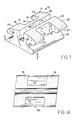
- Figure 1 is an enlarged perspective view of an orthodontic bracket made in accordance with the present invention;
- Figure 1A is a front elevational view of the bracket of Figure 1;
- Figure 2 is a cross-sectional view of the bracket of Figure 1 taken along line 2-2;
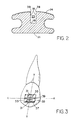
- Figure 3 is a front elevational view of the bracket of Figure 1 illustrating the bracket in relationship to its position against the tooth in which it is to be secured;
- Figure 4 is a perspective view of a modified orthodontic bracket made in accordance with the present invention; and
- Figure 4A is a front elevational view of the bracket of Figure 4;
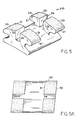
- Figure 5 is a perspective view of yet another modified embodiment of an orthodontic bracket made in accordance with the present invention;
- Figure 5A is a front elevational view of the bracket of Figure 5;
- Figure 6 is a perspective view of still another modified embodiment of an orthodontic bracket made in accordance with the present invention; and
- Figure 6A is a front elevational view of the bracket of Figure 6.
- Referring to Figures 1-3 there is illustrated an
orthodontic bracket 10 made in accordance with the present invention. In the embodiment illustrated the bracket is made of a translucent or transparent material and in the particular embodiment illustrated,bracket 10 is made of polycrystalline alumina material. However, it is to be understood thatbracket 10 may be made of any crystalline or non-crystalline material desired.Bracket 10 comprises of a pair oftiewings portions 15 which are supported bybase 20 having atooth contract surface 21 for attachment to the tooth. Thetiewings portions 15 form a pair ofopposed sidewalls 18 which forms anarchwire slot 23 for receiving an orthodontic archwire (not shown) as is typically done in prior art. A substantiallyflat bottom wall 19 connectssidewalls 18 and form the bottom ofslot 23. It should be understood that thebracket 10 may be of any desired configuration, for example as used in the prior art, or as further developed, with the configuration illustrated in Figure 1 being for the purpose of illustration only. - The
tiewings portions 15 provide a frontlabial face 22 which faces the inside portion of the adjacent lips of a patient. For the purpose of the present invention, the front labial face of the bracket shall be considered that portion of the surface of the bracket, as viewed in a front elevational view of the bracket as illustrated in Figure 3, which faces the labial side of the patient. Thelabial face 22 is bounded at its perimeter byouter tiewing edges 33,inner tiewing edges 31,top tiewing edges 35,bottom tiewing edges 37,slot edges 39 andedges 41.Bracket 10 is provided with aremovable layer 24 which is made of a material having a color which is in visual contrast with that of the adjacent tooth upon which theorthodontic bracket 10 is to be secured. In the particular embodiment illustrated,removable layer 24 is made of a non-toxic black-colored water-soluble ink which has been applied to the front labial face of the bracket. Suitable dyes or inks may be purchased from the Markem Corporation of Keene, NH. It is, of course, understood that various other colors may be used, for example, but not limited to, pink, red, green, so long as substantial visual contrast in color is provided with respect to the tooth. Florescent type colors are quite suitable for this purpose. - At least one edge of
labial face 22 is parallel to the longitudinal axis y-y of the tooth and at least one reference edge which is substantially parallel to the occlusal plane of the patient as represented by line x-x in Figure 3. The longitudinal axis y-y is a well-known referenced plane which is approximated by visualizing the long axis of the crown and only the visual component of the tooth. Thebracket 10 has at least one referenced edge which is parallel to the occlusal plane and one reference edge is substantially parallel to the longitudinal axis y-y of the tooth. For a complete understanding of these reference edges, Applicant refers to U.S. Patent 4,415,330 which describes an orthodontic bracket having a plurality of reference edges which are parallel with either the occlusal of longitudinal axis of the tooth. - In the particular embodiment illustrated,
edges edges front face 22 has an edge which is parallel either to the occlusal plane or longitudinal axis of the tooth. Theouter layer 24 completely fills the area within this perimeter. Thus, since thelayer 24 is made of a highly visible-colored material with respect to the color of the tooth, the reference edges can be more readily viewed by the orthodontists. It should be understood that the present invention is not limited to the particular configuration bracket illustrated in Figures 1-3, nor is the bracket required to have as many reference edges as illustrated in the referenced embodiment. While the preferred embodiment illustrates all of the edges being substantially parallel to either the x-x or y-y plane, only as many edges necessary for alignment with each axis need be highlighted. - Referring to Figure 4, there is illustrated a modified
orthodontic bracket 110 made in accordance with the present invention. In this particular embodiment there is illustrated a single wing-type bracket, and thus, does not have connectingportions 15 nor inside edges 31. Theorthodontic bracket 110 is provided as a frontlabial face 122 having afront edge 135, abottom edge 137, anouter edges 133. Theedges front surface 122 is provided with a layer 124 substantially identical to layer 24 with regard to the embodiment illustrated in Figures 1-3. In this embodiment, a substantially greater amount of surface area is provided which provides a greater surface area which is easier to visually view and provides longer, continuous alignment edges. - Referring to Figure 5, there is illustrated yet another modified embodiment of an
orthodontic bracket 210 made in accordance with the present invention. Like numerals, again representing like parts. In this embodiment, the orthodontic bracket is similar to that illustrated in Figures 1-3, except the connectingportions 15 are omitted. However, the bracket still hasedges - In the preferred embodiment illustrated, the entire area within the perimeter of the alignment edges is coated with
removable layer 24. However, the present invention is not so limited, as other means may be provided to visually enhance the appearance of the alignment edges, for example, a narrow removable band or strip 311 of dye that may be placed adjacent the alignment edges 31, 33, 35, 37 so as to form an outline of the perimeter and/or desired alignment edges as illustrated in Figure 6. Here again like represent like parts. As can be seen, a portion of the perimeter offace 22 ofbracket 310 is not outlined with strip 311. - The removable layer or narrow band in the present embodiment may be applied in any desired fashion. In the preferred embodiment, the removable layer comprises a coating of a non-toxic ink applied by a roller, sprayer or brush. However, the present invention is not so limited.
- In order to more fully understand the orthodontic bracket of the present invention and its use, Applicant will now discuss in detail how the bracket is applied. First, a bracket according to one of the embodiments as illustrated in Figures 1-6 is obtained. The
removable layer 24 or outline will have preferably already been applied to the front labial face of the bracket, or is applied at that time. The bracket will have at least an alignment edge for alignment with each of the reference planes. The bracket is then secured to the tooth in the desired manner. For example, but not limited to, applying the appropriate adhesive to the tooth contact surface of thebracket 10. The bracket is then properly aligned and secured to the tooth. The reference edges 31,33 aid the orthodontist in aligning the bracket with the long longitudinal axis y-y of the tooth and theedges removable layer 24 is then removed, thus ensuring the aesthetic quality of bracket will not be diminished. In the particular embodiment illustrated, thelayer 24 is a water-soluble dye which is simply removed by applying water. In the particular embodiment illustrated, a light rubbing action in addition to the water will cause the dye to be easily removed from the frontlabial surface 22. - It is to be understood that various changes and/or modifications may be made without departing from the scope of the present invention. For example, but not by way of limitation, other non-toxic means may be applied to the front labial surface of the bracket such as a non-aqueous based ink which can be removed from the tooth by the application of an ethanol rinse having about 10% to 30% ethanol. Additionally, the present invention is not limited to the application of inks. A decal having the approximate configuration may be placed on the front labial surface of the bracket with an appropriate tack adhesive. After installation of the bracket on the tooth, the decal would simply be peeled off and the bracket cleaned. The present invention, in addition to being applicable to brackets having edges designed to align with predetermined reference planes, the present invention may be adopted for use with brackets which do not have edges which align with reference planes, such as the tooth long axis or occlusal plane. In such situations, the layer will be configured such that it provides the appropriate alignment edges for alignment with the reference plane. Thus, a bracket which does not have any reference edges can be easily and economically modified by the application of colored layer having edges which align with the long axis or occlusal plane of the patient. Typically the layer would have a generally rhomboidal outer configuration.
Claims (21)
a front labial face having an outer perimeter having at least one referencence edge for alignment with a first reference plane and at least one second reference edge for alignment with a second reference plane; and
removable means placed on said front labial face for enhancing the visual contrast of said first and second reference edges with respect to said tooth.
Applications Claiming Priority (2)
| Application Number | Priority Date | Filing Date | Title |
|---|---|---|---|
| US07/437,199 US5074783A (en) | 1989-11-16 | 1989-11-16 | Orthodontic bracket coated with water-soluble dye |
| US437199 | 1989-11-16 |
Publications (2)
| Publication Number | Publication Date |
|---|---|
| EP0429263A1 true EP0429263A1 (en) | 1991-05-29 |
| EP0429263B1 EP0429263B1 (en) | 1995-04-26 |
Family
ID=23735500
Family Applications (1)
| Application Number | Title | Priority Date | Filing Date |
|---|---|---|---|
| EP90312506A Expired - Lifetime EP0429263B1 (en) | 1989-11-16 | 1990-11-16 | Orthodontic bracket |
Country Status (5)
| Country | Link |
|---|---|
| US (1) | US5074783A (en) |
| EP (1) | EP0429263B1 (en) |
| JP (1) | JPH0616796B2 (en) |
| AT (1) | ATE121611T1 (en) |
| DE (1) | DE69018937T2 (en) |
Cited By (1)
| Publication number | Priority date | Publication date | Assignee | Title |
|---|---|---|---|---|
| EP0656195A3 (en) * | 1993-11-29 | 1995-08-16 | Minnesota Mining & Mfg | Ceramic orthodontic bracket with debonding channel. |
Families Citing this family (14)
| Publication number | Priority date | Publication date | Assignee | Title |
|---|---|---|---|---|
| US5252066A (en) * | 1992-08-28 | 1993-10-12 | Johnson & Johnson Consumer Products, Inc. | Orthodontic bracket formed from porcelain fused to metallic material |
| CA2139078C (en) * | 1993-12-23 | 1998-04-21 | James A. Nicholson | Orthodontic brackets |
| JP3364728B2 (en) * | 1994-04-13 | 2003-01-08 | トミー株式会社 | Orthodontic bracket |
| US5692895A (en) * | 1995-01-30 | 1997-12-02 | Ormco Corporation | Luminescent orthodontic appliances |
| US5692896A (en) * | 1995-03-15 | 1997-12-02 | Minnesota Mining And Manufacturing Co. | Light-transmissive orthodontic bracket wth alignment and indentification marking |
| US5716208A (en) * | 1996-05-03 | 1998-02-10 | Forman; David | Orthodontic bracket with a water insoluble colored coating and the associated methods of manufacture and use |
| US5769634A (en) * | 1997-06-02 | 1998-06-23 | Choi; John | Dental articulator |
| US5890893A (en) | 1998-02-26 | 1999-04-06 | Heiser; Wolfgang | Orthodontic bracket |
| DE10250983B4 (en) * | 2002-10-29 | 2007-01-25 | Bernhard Förster Gmbh | Orthodontic bracket |
| US7094052B2 (en) * | 2004-04-30 | 2006-08-22 | Norbert Abels | Orthodontic brackets with temporarily visible marking features |
| JP5770630B2 (en) * | 2008-08-13 | 2015-08-26 | オルムコ コーポレイション | Aesthetic orthodontic bracket and manufacturing method thereof |
| AU2009238317B2 (en) * | 2008-11-14 | 2011-10-06 | Ormco Corporation | Surface treated polycrystalline ceramic orthodontic bracket and method of making same |
| WO2013028396A1 (en) * | 2011-08-24 | 2013-02-28 | 3M Innovative Properties Company | Orthodontic appliances with dissolvable coatings |
| JP5642259B1 (en) * | 2013-12-31 | 2014-12-17 | 尋士 山田 | Orthodontic bracket |
Citations (3)
| Publication number | Priority date | Publication date | Assignee | Title |
|---|---|---|---|---|
| US3521355A (en) * | 1969-06-30 | 1970-07-21 | Lawrence Pearlman | Positioning means for orthodontic brackets |
| US4523908A (en) * | 1979-12-07 | 1985-06-18 | Giovanni Drisaldi | Device for positioning and protecting an orthodontic bracket |
| EP0389225A1 (en) * | 1989-03-20 | 1990-09-26 | JOHNSON & JOHNSON CONSUMER PRODUCTS, INC. | Axis indicator for orthodontic bracket |
Family Cites Families (10)
| Publication number | Priority date | Publication date | Assignee | Title |
|---|---|---|---|---|
| US3496637A (en) * | 1967-08-15 | 1970-02-24 | Milton Etengoff | Orthodontic bracket-band construction |
| US4299569A (en) * | 1976-03-08 | 1981-11-10 | Leonard Frantz | Orthodontic bracket for straightening teeth |
| US4050156A (en) * | 1976-06-28 | 1977-09-27 | Daniel Chasanoff | Dental appliance |
| US4134208A (en) * | 1976-09-22 | 1979-01-16 | Lawrence Pearlman | Adjustable positioning means for orthodontic brackets |
| DE2903768B2 (en) * | 1979-02-01 | 1980-11-20 | Dentaurum Hans-Peter Winkelstroeter Kg, 7536 Ispringen | Wire retaining element for orthodontic purposes |
| US4415330A (en) * | 1979-05-04 | 1983-11-15 | Sybron Corporation | Orthodontic bracket assembly |
| US4551096A (en) * | 1983-12-19 | 1985-11-05 | Dellinger Eugene L | Orthodontic apparatus and method for treating malocclusion |
| US4626208A (en) * | 1985-08-16 | 1986-12-02 | Tp Orthodontics, Inc. | Positioning jig for edgewise bracket |
| US4819316A (en) * | 1987-07-29 | 1989-04-11 | Rmo, Inc. | Method of making a pre-adjusted orthodontic bracket assembly |
| US4952141A (en) * | 1988-03-22 | 1990-08-28 | Wool Arthur L | High visibility orthodontic arch wire slot |
-
1989
- 1989-11-16 US US07/437,199 patent/US5074783A/en not_active Expired - Lifetime
-
1990
- 1990-11-15 JP JP30737290A patent/JPH0616796B2/en not_active Expired - Lifetime
- 1990-11-16 DE DE69018937T patent/DE69018937T2/en not_active Expired - Lifetime
- 1990-11-16 AT AT90312506T patent/ATE121611T1/en not_active IP Right Cessation
- 1990-11-16 EP EP90312506A patent/EP0429263B1/en not_active Expired - Lifetime
Patent Citations (3)
| Publication number | Priority date | Publication date | Assignee | Title |
|---|---|---|---|---|
| US3521355A (en) * | 1969-06-30 | 1970-07-21 | Lawrence Pearlman | Positioning means for orthodontic brackets |
| US4523908A (en) * | 1979-12-07 | 1985-06-18 | Giovanni Drisaldi | Device for positioning and protecting an orthodontic bracket |
| EP0389225A1 (en) * | 1989-03-20 | 1990-09-26 | JOHNSON & JOHNSON CONSUMER PRODUCTS, INC. | Axis indicator for orthodontic bracket |
Cited By (2)
| Publication number | Priority date | Publication date | Assignee | Title |
|---|---|---|---|---|
| EP0656195A3 (en) * | 1993-11-29 | 1995-08-16 | Minnesota Mining & Mfg | Ceramic orthodontic bracket with debonding channel. |
| EP1004279A1 (en) * | 1993-11-29 | 2000-05-31 | Minnesota Mining And Manufacturing Company | Ceramic orthodontic bracket with debonding channel |
Also Published As
| Publication number | Publication date |
|---|---|
| US5074783A (en) | 1991-12-24 |
| ATE121611T1 (en) | 1995-05-15 |
| JPH03173557A (en) | 1991-07-26 |
| DE69018937D1 (en) | 1995-06-01 |
| JPH0616796B2 (en) | 1994-03-09 |
| DE69018937T2 (en) | 1995-09-21 |
| EP0429263B1 (en) | 1995-04-26 |
Similar Documents
| Publication | Publication Date | Title |
|---|---|---|
| EP0429263B1 (en) | Orthodontic bracket | |
| US5931667A (en) | Orthodontic apparatus and method | |
| EP0455500B1 (en) | Relatively flexible bonding pad or base for an orthodontic bracket | |
| US5692896A (en) | Light-transmissive orthodontic bracket wth alignment and indentification marking | |
| EP1804710B1 (en) | Combination of an apparatus for applying orthodontic appliances and of an apparatus for applying a composition to a patient's teeth | |
| JP3334940B2 (en) | Pad with flexibility | |
| US5022854A (en) | Orthodontic bracket | |
| US5176517A (en) | Dental undercut application device and method of use | |
| US6893257B2 (en) | Orthodontic appliance with placement enhancement structure | |
| US5114341A (en) | Dental matrix | |
| US20060204918A1 (en) | Self-ligating orthodontic bracket | |
| US20030118967A1 (en) | Orthodontic snap-in bracket | |
| US5607301A (en) | Orthodontic bracket and method of mounting | |
| EP0472656B1 (en) | Dental matrix | |
| US20250302593A1 (en) | Bracket Identification Marking System | |
| KR20110117660A (en) | Orthodontic bracket | |
| US4952141A (en) | High visibility orthodontic arch wire slot | |
| US11957535B1 (en) | Preparation tray for improved etching and bonding of a tooth surface prior to the placement of a tooth attachment or a bracket | |
| US20100129764A1 (en) | Ceramic orthodontic bracket with improved debonding characteristics | |
| US10779910B2 (en) | Orthodontic bracket axis indicator | |
| US5076784A (en) | Orthodontic mirror | |
| US7044733B2 (en) | Mounting aid for mounting an orthodontic bracket to a tooth | |
| JPH08112293A (en) | Orthodontic bracket | |
| JPH02268754A (en) | Axial indicator for orthodontic bracket | |
| JPH03168142A (en) | Orthodontic bracket cap |
Legal Events
| Date | Code | Title | Description |
|---|---|---|---|
| PUAI | Public reference made under article 153(3) epc to a published international application that has entered the european phase |
Free format text: ORIGINAL CODE: 0009012 |
|
| AK | Designated contracting states |
Kind code of ref document: A1 Designated state(s): AT CH DE ES FR GB IT LI SE |
|
| 17P | Request for examination filed |
Effective date: 19910610 |
|
| 17Q | First examination report despatched |
Effective date: 19921127 |
|
| GRAA | (expected) grant |
Free format text: ORIGINAL CODE: 0009210 |
|
| AK | Designated contracting states |
Kind code of ref document: B1 Designated state(s): AT CH DE ES FR GB IT LI SE |
|
| PG25 | Lapsed in a contracting state [announced via postgrant information from national office to epo] |
Ref country code: IT Free format text: LAPSE BECAUSE OF FAILURE TO SUBMIT A TRANSLATION OF THE DESCRIPTION OR TO PAY THE FEE WITHIN THE PRESCRIBED TIME-LIMIT;WARNING: LAPSES OF ITALIAN PATENTS WITH EFFECTIVE DATE BEFORE 2007 MAY HAVE OCCURRED AT ANY TIME BEFORE 2007. THE CORRECT EFFECTIVE DATE MAY BE DIFFERENT FROM THE ONE RECORDED. Effective date: 19950426 Ref country code: CH Effective date: 19950426 Ref country code: AT Effective date: 19950426 Ref country code: LI Effective date: 19950426 Ref country code: ES Free format text: THE PATENT HAS BEEN ANNULLED BY A DECISION OF A NATIONAL AUTHORITY Effective date: 19950426 |
|
| REF | Corresponds to: |
Ref document number: 121611 Country of ref document: AT Date of ref document: 19950515 Kind code of ref document: T |
|
| REF | Corresponds to: |
Ref document number: 69018937 Country of ref document: DE Date of ref document: 19950601 |
|
| ET | Fr: translation filed | ||
| PG25 | Lapsed in a contracting state [announced via postgrant information from national office to epo] |
Ref country code: SE Effective date: 19950726 |
|
| REG | Reference to a national code |
Ref country code: CH Ref legal event code: PL |
|
| PG25 | Lapsed in a contracting state [announced via postgrant information from national office to epo] |
Ref country code: GB Effective date: 19951116 |
|
| PLBE | No opposition filed within time limit |
Free format text: ORIGINAL CODE: 0009261 |
|
| STAA | Information on the status of an ep patent application or granted ep patent |
Free format text: STATUS: NO OPPOSITION FILED WITHIN TIME LIMIT |
|
| 26N | No opposition filed | ||
| GBPC | Gb: european patent ceased through non-payment of renewal fee |
Effective date: 19951116 |
|
| PGFP | Annual fee paid to national office [announced via postgrant information from national office to epo] |
Ref country code: DE Payment date: 20091127 Year of fee payment: 20 |
|
| PGFP | Annual fee paid to national office [announced via postgrant information from national office to epo] |
Ref country code: FR Payment date: 20091201 Year of fee payment: 20 |
|
| PG25 | Lapsed in a contracting state [announced via postgrant information from national office to epo] |
Ref country code: DE Free format text: LAPSE BECAUSE OF EXPIRATION OF PROTECTION Effective date: 20101116 |