EP0429300A2 - System mit mehreren in einer vorbestimmten Folge auf einen Anruf ansprechenden Endgeräten - Google Patents
System mit mehreren in einer vorbestimmten Folge auf einen Anruf ansprechenden Endgeräten Download PDFInfo
- Publication number
- EP0429300A2 EP0429300A2 EP90312669A EP90312669A EP0429300A2 EP 0429300 A2 EP0429300 A2 EP 0429300A2 EP 90312669 A EP90312669 A EP 90312669A EP 90312669 A EP90312669 A EP 90312669A EP 0429300 A2 EP0429300 A2 EP 0429300A2
- Authority
- EP
- European Patent Office
- Prior art keywords
- incoming call
- terminal
- time
- terminal apparatuses
- terminal apparatus
- Prior art date
- Legal status (The legal status is an assumption and is not a legal conclusion. Google has not performed a legal analysis and makes no representation as to the accuracy of the status listed.)
- Withdrawn
Links
Images


Classifications
-
- H—ELECTRICITY
- H04—ELECTRIC COMMUNICATION TECHNIQUE
- H04Q—SELECTING
- H04Q11/00—Selecting arrangements for multiplex systems
- H04Q11/04—Selecting arrangements for multiplex systems for time-division multiplexing
- H04Q11/0428—Integrated services digital network, i.e. systems for transmission of different types of digitised signals, e.g. speech, data, telecentral, television signals
- H04Q11/0435—Details
- H04Q11/0471—Terminal access circuits
-
- H—ELECTRICITY
- H04—ELECTRIC COMMUNICATION TECHNIQUE
- H04Q—SELECTING
- H04Q11/00—Selecting arrangements for multiplex systems
- H04Q11/04—Selecting arrangements for multiplex systems for time-division multiplexing
-
- H—ELECTRICITY
- H04—ELECTRIC COMMUNICATION TECHNIQUE
- H04M—TELEPHONIC COMMUNICATION
- H04M1/00—Substation equipment, e.g. for use by subscribers
- H04M1/71—Substation extension arrangements
- H04M1/715—Substation extension arrangements using two or more extensions per line
-
- H—ELECTRICITY
- H04—ELECTRIC COMMUNICATION TECHNIQUE
- H04M—TELEPHONIC COMMUNICATION
- H04M11/00—Telephonic communication systems specially adapted for combination with other electrical systems
- H04M11/06—Simultaneous speech and data transmission, e.g. telegraphic transmission over the same conductors
-
- H—ELECTRICITY
- H04—ELECTRIC COMMUNICATION TECHNIQUE
- H04Q—SELECTING
- H04Q2213/00—Indexing scheme relating to selecting arrangements in general and for multiplex systems
- H04Q2213/07—Call distribution; Call detection; Call signalling by common apparatus
-
- H—ELECTRICITY
- H04—ELECTRIC COMMUNICATION TECHNIQUE
- H04Q—SELECTING
- H04Q2213/00—Indexing scheme relating to selecting arrangements in general and for multiplex systems
- H04Q2213/25—Preferential service
-
- H—ELECTRICITY
- H04—ELECTRIC COMMUNICATION TECHNIQUE
- H04Q—SELECTING
- H04Q2213/00—Indexing scheme relating to selecting arrangements in general and for multiplex systems
- H04Q2213/31—Delay devices; Circuits, e.g. shift memories
Definitions
- the present invention relates to a terminal system which is connected to a communication network and contains a plurality of terminal apparatuses, where the plurality of terminal apparatuses are connected to the communication network through a two-way bus line.
- the present invention relates, in particular, to an ISDN (Integrated Services Digital Network) terminal system which is connected to an ISDN network, and contains a plurality of ISDN terminal apparatuses, such as a telephone set, a facsimile terminal apparatus, a personal computer, and the like.
- a plurality of terminal apparatuses can be connected to an ISDN network through a digital service unit (DSU) at each subscriber location.
- DSU digital service unit
- FIG. 1 shows an overall construction of an ISDN terminal system to which the present invention is applicable.
- reference numeral 7 denotes an ISDN network
- 8 denotes a digital service unit (DSU)
- 5 denotes a two-way bus line
- 9 denotes a plurality of terminal apparatuses
- the terminal apparatuses are respectively denoted by A, B, C, D, E, F, G, and H.
- a plurality of ISDN terminal apparatuses are connected to a digital service unit through a two-way bus line.
- a plurality of facsimile terminal apparatuses are connected to a digital service unit through a two-way bus line, and some subscribers may require use of a part of the plurality of facsimile terminal apparatuses for sending facsimile data only, and the other part of the plurality of facsimile terminal apparatuses for receiving facsimile data only.
- a request to set up a call from an ISDN network is reaches at the digital service unit
- the request to set up a call is supplied to all the terminal apparatuses which are connected to the digital service unit through the two-way bus line.
- Each of the terminal apparatuses responds to the request when the above request is supplied thereto.
- each ISDN terminal apparatus generally a response time of each ISDN terminal apparatus is intrinsic to each terminal apparatus due to individual variations of the constructions of the terminal apparatuses, and further varies depending on whether or not a microprocessor which must process the responding operation is busy when the terminal apparatus receives the above request.
- the ISDN network accepts and acknowledges a response from a terminal apparatus which first responds to the above request only. Therefore, in spite of the above subscribers' request, generally, it is not known which terminal apparatus among all the terminal apparatuses first responds to the request.
- each terminal apparatus comprises an incoming call indication (alerting) unit, a signal processing unit for receiving a SETUP message from an exchange, returning an ALERT message to the exchange and outputting an alert start signal when the incoming call can be received thereat, and outputting an alert stop signal when a RELEASE signal is received thereat from the exchange.
- Each terminal apparatus further comprises: a timer which starts counting time responding to the above alert start signal, starts an operation of the incoming call indication (alerting) unit when a preset time has been counted, and stops the time counting responding to the alert stop signal; and a priority order switching unit for supplying in advance the preset time to the timer in accordance with a priority order.
- each terminal apparatus comprises: a connection information registering means for registering a number of calling parties from which the incoming calls are expected to be received, and priority orders corresponding to the calling parties which are assigned to the terminal apparatus; an incoming call determining means for determining whether or not an incoming call is acceptable; and a control means for controlling the timing of sending of a response to the acceptable incoming call, based on the connect on information in the connection information registering means.
- the control means sends a request to immediately send a response to a response sending portion when the priority order is the first order; or starts the timer, and sends a request to send a response to a response sending portion when a predetermined time has elapsed after the timer starts when the priority order is lower than the first order.
- connection information registering means must been provided.
- the above terminal station cannot respond to an incoming call from a calling part/ which is not determined as acceptable, i.e., which is not registered in advance.
- An object of the present invention is to provide a terminal system containing a plural of of terminal apparatuses which are connected to communication network through a two-way bus line, wherein the terminal apparatuses automatically respond to an incoming call in an order the user of the systen requests, without a collision of the response signals, and each terminal apparatus is realized by a simple construction.
- a terminal system containing a plurality of terminal apparatuses, an interface unit, and a two-way bus line connecting thereto the plurality of terminal apparatuses.
- the interface unit which is connected on one side thereof to an communication network, and on the other side thereof to the above two-way bus line, functions as an interface between the communication network and each of the plurality o terminal apparatuses regarding two-way transmission of data signals and control signals for the transmission of the data signals and control signals.
- Each of the plurality of terminal apparatuses comprises an incoming call detecting unit and a responding unit.
- the incoming call detecting unit detects an incoming call to which the terminal apparatus can respond, where the incoming call detecting unit belongs to the terminal apparatus, and the responding unit responds to an incoming call which is detected in the incoming call detecting unit, where the responding unit has a response time which is needed to respond to the incoming call, and is intrinsic to each terminal apparatus.
- Each of the plurality of terminal apparatuses further contains a timer unit which detects when a time elapsed from a time at which an incoming call is detected in the incoming call detecting unit, reaches a preset time.
- the above responding unit in each terminal apparatus starts an, operation of responding to the incoming call when the timer unit detects that the above elapsed time reaches the preset time; and an order of priority to respond to an incoming call is predetermined over the plurality of terminal apparatuses, and lengths of the preset times in the plurality of terminal apparatuses are preset in the order of the predetermined priority.
- Figure 2 shows the construction of a facsimile terminal apparatus which is connected to the two-way bus line 5 of Fig. 1, according to the first embodiment of the present invention.
- reference numeral 21 denotes a keyboard
- 22 denotes a key input control unit
- 23 denotes an MPU
- 24 denotes a timer
- 25 denotes an LCD display unit
- 26 denotes a display control unit
- 27 denotes a coded image data memorizing unit
- 28 denotes a communication control unit
- 29 denotes a program ROM
- 30 denotes a program working memory
- 31 denotes a setting data memory
- 32 denotes a CG developing circuit
- 33 denotes a character image ROM
- 34 denotes a decompression circuit
- 35 denotes a print control circuit
- 36 denotes a printer
- 37 denotes a reading control circuit
- 38 denotes a scanner.
- the keyboard 21 is provided for an operator to input instructions and data to be set in the facsimile terminal apparatus, and the instructions and data input from the keyboard 21 are transferred through the keyboard control circuit 22 to the MPU 23.
- the LCD display unit 25 displays information for the operator, for example, when the operator inputs data and instructions, or when the operator requests to see the state of the facsimile terminal apparatus.
- the display control unit 26 controls the operation of the LCD display unit 25.
- the MPU 23 executes a program which is stored in the program ROM 29, using the program working memory 30 and the setting data memory 31 to control the overall operation of the facsimile terminal apparatus of Fig. 2.
- the character image ROM 33 memorizes character images corresponding to character codes.
- the CG developing circuit 32 generates a character image by referring to the character image ROM 33 for a character code which is supplied from the MPU 23.
- the coded image data memorizing unit 27 is a buffer memory for temporarily storing coded data which is received through the communication control circuit 28 from the ISDN network.
- the decompression circuit 34 is constructed by a hardware logic circuit, and decompresses (decodes) received coded data to bit map data, where the coded data is read from the coded image data memorizing unit 27.
- the decompressed data is printer by the printer 36 under the control of the print control circuit 35.
- the scanner 38 and the reading control circuit 37 are provided for reading a draft or figure to be input.
- the timer 24 can start or stop counting time, reset the count, and be preset for the preset time, under the control of the MPU 23.
- the timer 24 starts the counting of time under the control of the MPU 23 when a SETUP message is received from the ISDN network, and informs the MPU 23 of a time out of the preset time to make the MPU 23 send a CONNECT message to the ISDN network.
- Figure 3 is a flowchart of the operation of the facsimile terminal apparatus of Fig. 2 according to the second embodiment of the present invention.
- an operation of receiving a message begins.
- a SETUP message is received.
- the SETUP message addresses a particular one of the terminal apparatuses in the terminal system, in the step 63.
- data communication proceeds in the conventional manner wherein no control is carried out for the timing of response.
- no is determined in the step 63 it is determined whether or not the terminal apparatus is in a state where it is able to receive the SETUP message in the step 64.
- a DISCONNECT message is sent to the ISDN network in the step 74.
- a RELEASE COMPLETE message is sent to the ISDN network in the step 76.
- the operation is completed in the step 77.
- a time counting operation for a preset time begins in the step 65.
- a CONNECT message is sent to the ISDN network in the step 67.
- the operation goes to the step 76 to complete the operation.
- a RELEASE message is not received in the step 68, and a RELEASE COMPLETE message is received in the step 69, a transfer operation of facsimile data is carried out in the step 70.
- a DISCONNECT message is sent from the ISDN network.
- a RELEASE message is sent to the ISDN network in the step 72.
- a RELEASE COMPLETE message is received in the step 73, the operation is completed in the step 7.
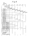
- Figures 6 to 8 are each example sequence diagrams of an operation of the ISDN terminal system when a SETUP message is received from the ISDN network, where facsimile terminal apparatuses in the ISDN terminal system, each having a construction as shown in Fig. 2 and operating as shown in Fig. 3, are connected to a digital service unit as shown in Fig. 1.
- facsimile terminal apparatuses in the ISDN terminal system each having a construction as shown in Fig. 2 and operating as shown in Fig. 3, are connected to a digital service unit as shown in Fig. 1.
- Figs. 1 In the examples of Figs.
- the preset times which are preset for the timers 12 in the facsimile terminal apparatuses A, B, C, D, E, F, G, and H, are respectively denoted by a, b, c, d, e, f, g, and h (seconds), where a ⁇ b ⁇ c ⁇ d ⁇ e ⁇ f ⁇ g ⁇ h.
- Figure 4 is an example sequence diagram for a case when all the terminal apparatuses A B, C, D, E, F, G, and H, are not busy.
- the terminal apparatus A when a SETUP message is received in the terminal systen, the terminal apparatus A sends a CONNECT message to the ISDN network after an elapse of time a, the terminal apparatus B sends a CONNECT message to the ISDN network after an elapse of time b, the terminal apparatus C sends a CONNECT message to the ISDN network after an elapse of time c, the terminal apparatus D sends a CONNECT message to the ISDN network after an elapse of time d, the terminal apparatus E sends a CONNECT message to the ISDN network after an elapse of time e, the terminal apparatus F sends a CONNECT message to the ISDN network after an elapse of time f, the terminal apparatus G sends a CONNECT message to the ISDN network after an elapse of time g, and the terminal
- the ISDN network returns a CONNECT ACKNOWLEDGE message to one of the terminal apparatuses which first returned the CONNECT message to the network, and sends a RELEASE message to all the other terminal apparatuses B, C, D, E, F, G, and H
- the other terminal apparatuses B, C, D, E, F, G, and H return a RELEASE COMPLETE message to the network to complete communication between the network and the terminal apparatuses B, C, D, E, F, G, and H respectively.
- facsimile data is transferred to the terminal apparatus A which first returned the CONNECT message to the network, and a calling party through the ISDN network.
- a DISCONNECT message is transferred from the calling party through the ISDN network to the terminal system.
- the terminal apparatus A receives the DISCONNECT message, the terminal apparatus A returns a RELEASE message to the network.
- the ISDN network returns a RELEASE COMPLETE message to complete the operation.
- Figure 5 is an example sequence diagram for a case when the terminal apparatuses B, C, D, E, F, G, and H, except the terminal apparatus A, are not busy, but the terminal apparatus A is busy when a SETUP message is received in the terminal apparatus A.
- the terminal apparatus A when a SETUP message is received in the terminal system, the terminal apparatus A returns a DISCONNECT message to the ISDN network since the terminal apparatus A is busy, and the terminal apparatus B sends a CONNECT message to the ISDN network after an elapse of time b, the terminal apparatus C sends a CONNECT message to the ISDN network after an elapse of time c, ....
- the terminal apparatus H sends a CONNECT message to the ISDN network after an elapse of time h.
- the terminal apparatus B first returns the CONNECT message to the network, and therefore, the network returns a CONNECT ACKNOWLEDGE message to the terminal apparatus B only.
- facsimile data is transferred to the terminal apparatus B.
- the network sends a RELEASE message to all the other terminal apparatuses A, C, D, E, F, G, and H, and the other terminal apparatuses A, C, D, E, F, G, and H return a RELEASE COMPLETE message tO the network to complete communication between the network and the terminal apparatuses A, C, D, E, F, G, and H, respectively.
- Figure 6 is an example sequence diagram for a case when all the terminal apparatuses A, B, C, D, E, F, G, and H, are not busy, but the terminal apparatus A is out of order when a SETUP message is received in the terminal apparatus A, and therefore the terminal apparatus A cannot respond to the SETUP message.
- the terminal apparatus A when a SETUP message is received in the terminal system, the terminal apparatus A cannot return any message to the ISDN network, and the terminal apparatus B sends a CONNECT message to the ISDN network after an elapse of time b, the terminal apparatus C sends a CONNECT message to the ISDN network after an elapse of time c, ....
- the terminal apparatus H sends a CONNECT message to the ISDN network after an elapse of time h.
- the terminal apparatus B first returns the CONNECT message to network, and therefore, the network returns a CONNECT ACKNOWLEDGE message to the terminal apparatus B only.
- a facsimile data is transferred to the terminal apparatus B.
- the network sends a RELEASE message to all the other terminal apparatuses A, C, D, E, F, G, and H, and the other terminal apparatuses A, C, D, E, F, G, and H return a RELEASE COMPLETE message to the network to complete communication. between the network and the terminal apparatuses A, C, D, E, F, G, and H, respectively.
- Figure 7 shows an example of an operation panel which contains the keyboard 21 and the LCD display 25 of Fig. 2.
- the keyboard 21 contains keys which are denoted by "SET”, “COMPLETE”, “STOP”, “START”, and “FUNCTION”, in addition to a ten keyboard.
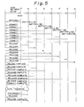
- Figure 8 shows an example of a sequence of the keyboard operations and information displayed on the LCD display 21.
- the display No. 1 indicates "READY” which means that the operator can input an instruction or preset data.
- the display No. 2 appears, where the display No. 2 indicates “Select a number of function.”
- the operator then pushes the key "1” to register a preset time for presetting a response time of the terminal apparatus.
- the display No. 3 appears, where the display No. 3 indicates "Input a response time.
- the display No. 4 appears, where the display No. 4 indicates "Push the SET key.
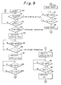
- Figure 9 is a flowchart of an operation of the operation panel of Fig. 7 for presenting a response time.
- the step 81 when it is determined that an incoming call is received in the terminal apparatus, in the step 81, the operation goes to Fig. 3.
- the step 81 When it is determined that no incoming call is received in, the step 81, and it is determined that there is a key input in the step 82, it is determined whether or not the function key is pushed in the step 83.
- the terminal apparatus goes to the other operation to wait for the other key operations which are not shown since that is out of the scope of the present invention.
- the LCD display 21 indicates the display No 2 in Fig. 8, in the step 84. Then, when it is determined in the steps 85 and 86, that the key "1" is pushed, the LCD display 21 indicates the display No. 3 in Fig. 8, in the step 87. When it is determined in the steps 88 and 89, that one of the keys “0" to “9” is pushed, the data corresponding to the key input is saved in the step 90. Then, when it is determined in the steps 91 and 92, that one of the keys “0" to “9” is pushed again, the key input is saved again in the step 93. Then, the LCD display 21 indicates the display No. 4 in Fig. 8, in the step 94. When it is determined in the steps 95 and 96, that the key "SET" is pushed, the indication of the LCD d splay 21 returns to the display No. 1 in Fig. 8, in the step 97.
- Figure 10 shows an overall construction of the terminal system which is connected to an analog communication network to which the present invention is applicable.
- reference numeral 104 denotes an analog communication network
- 105 denotes a two-way bus line
- 106 denotes a plurality of terminal apparatuses, where the terminal apparatus are respectively denoted by R1, R2, ... Rn.
- Figure 11 shows the construction of a data terminal apparatus which is connected to the two-way bus line 105 of Fig. 10, according to the second embodiment of the present invention.
- reference numeral 11 denotes a preset time input unit
- 12 denotes a main control unit
- 13 denotes a timer
- 1. denotes an accord detection unit
- 15 denotes a preset time memorizing unit
- 16 denotes a reception unit
- 17 denotes an incoming call detecting unit
- 18 denotes a response sending unit
- 19 denotes a network control unit (NCU)
- 5 indicates the above two-way bus line 5 of Fig. 1.
- the main control unit 12, the accord detection unit 14, the preset time memorizing unit 15, and the response sending unit 18 are realized by software operation executed in a microcomputer comprised of an MPU, ROM, and RAM (not shown), and the functions of the above units are as follows.
- the main control unit 12 controls all the operations of the terminal apparatus of Fig. 11.
- the network control unit 19 controls a connection between the terminal apparatus of Fig. 11 and the analog communication network.
- the network control unit 19 connects the terminal apparatus to the two way bus line 105, and detects and indicates an active ringing signal which is sent from the analog network.
- the incoming call detecting unit 18 detects and holds the active state of the ringing signal while the ringing signal is sent from the analog network, and the output of the incoming call detecting unit 18 to the main control unit 12.
- the main control unit 12 makes the timer 13 start counting time responding to the beginning of the active state of the above ringing signal, and makes the timer 13 stop the counting responding to the end of the active state of the ringing state and resets the timer 13.
- An operator can input a preset time through the preset time input unit 11.
- the preset time input from the preset time input unit 11 is written in the preset time memorizing unit 15 under the control of the main control unit 12.
- the accord detection unit 14 compares the time count in the timer 13 and the preset time memorized in the preset time memorizing unit 15 bv the software, and activates the response sending unit 18 when an accord is detected between the time count in the timer 13 and the preset time memorized in the preset time memorizing unit 15.
- the response sending unit 18 makes the network control unit 19 return a response to the ringing, and sends a response signal Ci, a called party number CED and a capability in information DIS of the terminal apparatus to the network.
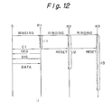
- Figure 12 is an example sequence of the operation of the terminal system containing three terminal apparatuses R1, R2, and R3 in the form as shown in Fig. 10, where each terminal apparatus has a construction as shown in Fig. 11, and the preset times in the terminal apparatuses are set as t1, t2, and t3, respectively, and t1 ⁇ t2 ⁇ t3.
- the ringing signal is supplied to all the terminal apparatuses R1, R2, and R3.
- the timers 13 in all the terminal apparatuses R1, R2, and R3 start counting time. After an elapse of time t1, the terminal apparatus R1 returns a response to the network, and receiving the response, the network stops the ringing signal to the terminal system. Detecting the stop of the ringing signal, the timers 12 in all the terminal apparatuses R1, R2, and R3 stop and are reset, and then, an operation or receiving data is carried out in the terminal apparatus R1.
- the main control unit 12 controls the response sending unit 18 not to send a response. Then, after an elapse of time t2, the terminal apparatus R2 sends a response to the network. Receiving the response, the network stops the ringing signal to the terminal system. When the ringing signal stops, the timers 12 in all the terminal apparatuses R1, R2, and R3 are reset and stop, and then, an operation of receiving data is carried out in the terminal apparatus R2.
- the reception of the data is preferentially carried out in the order of the lengths of the preset times t1, t2, and t3, without a collision of signals from the plurality of terminal apparatuses in the terminal system.
- the response time is preset in the above operation, alternatively, it is possible to input a priority order to the terminal apparatus by a similar operation.
- the MPU 23 in the construction of Fig. 2 or the main control unit 12 in the construction of Fig. 11 may calculate a preset time based on the priority order, and a higher priority order corresponds to a shorter preset time.
- the amount of the preset time may be about hundreds of milliseconds, which is sufficiently longer than the amount of the aforementioned individual difference of the response time in the conventional terminal apparatuses.
Landscapes
- Engineering & Computer Science (AREA)
- Computer Networks & Wireless Communication (AREA)
- Signal Processing (AREA)
- Facsimiles In General (AREA)
- Telephonic Communication Services (AREA)
- Communication Control (AREA)
Applications Claiming Priority (2)
| Application Number | Priority Date | Filing Date | Title |
|---|---|---|---|
| JP299756/89 | 1989-11-20 | ||
| JP1299756A JP2785835B2 (ja) | 1989-11-20 | 1989-11-20 | 通信端末装置および該装置を用いる通信端末システム |
Publications (2)
| Publication Number | Publication Date |
|---|---|
| EP0429300A2 true EP0429300A2 (de) | 1991-05-29 |
| EP0429300A3 EP0429300A3 (en) | 1992-08-05 |
Family
ID=17876599
Family Applications (1)
| Application Number | Title | Priority Date | Filing Date |
|---|---|---|---|
| EP19900312669 Withdrawn EP0429300A3 (en) | 1989-11-20 | 1990-11-20 | System of a plurality of terminal apparatuses respondent to a call in a predetermined order |
Country Status (3)
| Country | Link |
|---|---|
| EP (1) | EP0429300A3 (de) |
| JP (1) | JP2785835B2 (de) |
| KR (1) | KR940003162B1 (de) |
Families Citing this family (1)
| Publication number | Priority date | Publication date | Assignee | Title |
|---|---|---|---|---|
| JP5870585B2 (ja) * | 2011-09-28 | 2016-03-01 | ブラザー工業株式会社 | 通信装置及び通信システム |
Family Cites Families (1)
| Publication number | Priority date | Publication date | Assignee | Title |
|---|---|---|---|---|
| JPH0685538B2 (ja) * | 1986-05-07 | 1994-10-26 | 日本電気株式会社 | 通信端末着信応答方式 |
-
1989
- 1989-11-20 JP JP1299756A patent/JP2785835B2/ja not_active Expired - Lifetime
-
1990
- 1990-11-20 EP EP19900312669 patent/EP0429300A3/en not_active Withdrawn
- 1990-11-20 KR KR1019900018796A patent/KR940003162B1/ko not_active Expired - Fee Related
Also Published As
| Publication number | Publication date |
|---|---|
| EP0429300A3 (en) | 1992-08-05 |
| JPH03160869A (ja) | 1991-07-10 |
| KR910010943A (ko) | 1991-06-29 |
| JP2785835B2 (ja) | 1998-08-13 |
| KR940003162B1 (ko) | 1994-04-15 |
Similar Documents
| Publication | Publication Date | Title |
|---|---|---|
| US5216517A (en) | Communication terminal apparatus | |
| CA1281444C (en) | Facsimile apparatus | |
| JPH0522470A (ja) | データ通信装置 | |
| EP0429300A2 (de) | System mit mehreren in einer vorbestimmten Folge auf einen Anruf ansprechenden Endgeräten | |
| US5519508A (en) | Communication apparatus and method for delaying transmission to accept incoming calls | |
| US5808754A (en) | Facsimile machine with plural reception modes | |
| JPH03265269A (ja) | ファクシミリ装置の回線制御方式 | |
| KR0143169B1 (ko) | 통신단말기를 이용한 서비스 호출방법 | |
| JP3143129B2 (ja) | リダイヤル機能を備えた通信端末装置 | |
| KR0158482B1 (ko) | 팩시밀리의 수신 집중화 방법 | |
| JPH1168914A (ja) | ファクシミリ装置 | |
| JP2743272B2 (ja) | Isdn端末装置 | |
| JP3886655B2 (ja) | ファクシミリシステムおよびこのファクシミリシステムに用いられるファクシミリ装置 | |
| JP3119028B2 (ja) | 通信装置の発呼装置 | |
| KR100217758B1 (ko) | 전화단말장치의 원 터치 다이얼방법 | |
| KR100214329B1 (ko) | 무선호출기를 이용한 폴링 수신 요구방법 | |
| EP0447253B1 (de) | Verfahren und Terminaleinrichtung zur Verarbeitung ankommender Meldungen | |
| KR100247070B1 (ko) | 팩시밀리의 음성통화 예약기능에서 전화요청메세지 전송방법 | |
| KR100229022B1 (ko) | 원격 팩스자동송신방법 | |
| KR19980045603A (ko) | 전화단말장치의 다이얼정보 자동 학습 등록방법 | |
| JPH03289732A (ja) | 複数端末における着信処理方式及び端末 | |
| KR100201292B1 (ko) | 다수 공용형 팩시밀리에서 해당자로의 문서 수신 경보방법 | |
| JPH01246958A (ja) | ファクシミリ装置 | |
| KR19980075441A (ko) | 팩시밀리 메시지 수신 통보방법 | |
| KR19980074224A (ko) | 팩시밀리에서 발신자번호 및 착신시각 확인방법 |
Legal Events
| Date | Code | Title | Description |
|---|---|---|---|
| PUAI | Public reference made under article 153(3) epc to a published international application that has entered the european phase |
Free format text: ORIGINAL CODE: 0009012 |
|
| AK | Designated contracting states |
Kind code of ref document: A2 Designated state(s): DE FR GB |
|
| PUAL | Search report despatched |
Free format text: ORIGINAL CODE: 0009013 |
|
| AK | Designated contracting states |
Kind code of ref document: A3 Designated state(s): DE FR GB |
|
| STAA | Information on the status of an ep patent application or granted ep patent |
Free format text: STATUS: THE APPLICATION HAS BEEN WITHDRAWN |
|
| 18W | Application withdrawn |
Withdrawal date: 19921201 |
|
| R18W | Application withdrawn (corrected) |
Effective date: 19921127 |