EP0429309A2 - Polarisierungsweise zur Verbesserung der Eigenschaften der Drei-Niveau-Xerographie - Google Patents
Polarisierungsweise zur Verbesserung der Eigenschaften der Drei-Niveau-Xerographie Download PDFInfo
- Publication number
- EP0429309A2 EP0429309A2 EP90312719A EP90312719A EP0429309A2 EP 0429309 A2 EP0429309 A2 EP 0429309A2 EP 90312719 A EP90312719 A EP 90312719A EP 90312719 A EP90312719 A EP 90312719A EP 0429309 A2 EP0429309 A2 EP 0429309A2
- Authority
- EP
- European Patent Office
- Prior art keywords
- developer
- level
- bias
- tri
- developing
- Prior art date
- Legal status (The legal status is an assumption and is not a legal conclusion. Google has not performed a legal analysis and makes no representation as to the accuracy of the status listed.)
- Granted
Links
Images


Classifications
-
- G—PHYSICS
- G03—PHOTOGRAPHY; CINEMATOGRAPHY; ANALOGOUS TECHNIQUES USING WAVES OTHER THAN OPTICAL WAVES; ELECTROGRAPHY; HOLOGRAPHY
- G03G—ELECTROGRAPHY; ELECTROPHOTOGRAPHY; MAGNETOGRAPHY
- G03G15/00—Apparatus for electrographic processes using a charge pattern
- G03G15/01—Apparatus for electrographic processes using a charge pattern for producing multicoloured copies
- G03G15/0105—Details of unit
- G03G15/0121—Details of unit for developing
-
- G—PHYSICS
- G03—PHOTOGRAPHY; CINEMATOGRAPHY; ANALOGOUS TECHNIQUES USING WAVES OTHER THAN OPTICAL WAVES; ELECTROGRAPHY; HOLOGRAPHY
- G03G—ELECTROGRAPHY; ELECTROPHOTOGRAPHY; MAGNETOGRAPHY
- G03G13/00—Electrographic processes using a charge pattern
- G03G13/01—Electrographic processes using a charge pattern for multicoloured copies
- G03G13/013—Electrographic processes using a charge pattern for multicoloured copies characterised by the developing step, e.g. the properties of the colour developers
Definitions
- This invention relates generally to developer apparatus and methods for use in xerographic imaging.
- the invention can be utilized in the art of xerography or in the printing arts.
- conventional xerography it is the general procedure to form electrostatic latent images on a xerographic surface by first uniformly charging a photoconductive insulating surface or photoreceptor.
- the charge is selectively dissipated in accordance with a pattern of activating radiation corresponding to original images.
- the selective dissipation of the charge leaves a latent charge pattern on the imaging surface corresponding to the areas not struck by radiation.
- This charge pattern is made visible by developing it with toner.
- the toner is generally a colored powder which adheres to the charge pattern by electrostatic attraction.
- the developed image is then fixed to the imaging surface or is transferred to a receiving substrate such as plain paper to which it is fixed by suitable fusing techniques.
- the charge pattern is developed with toner particles of first and second colors.
- the toner particles of one of the colors are positively charged and the toner particles of the other color are negatively charged.
- the toner particles are supplied by a developer which comprises a mixture of triboelectrically relatively positive and relatively negative carrier beads.
- the carrier beads support, respectively, the relatively negative and relatively positive toner particles.
- Such a developer is generally supplied to the charge pattern by cascading it across the imaging surface supporting the charge pattern.
- the toner particles are presented to the charge pattern by a pair of magnetic brushes. Each brush supplies a toner of one color and one charge.
- the development system is biased to about the background voltage. Such biasing results in a developed image of improved color sharpness.
- the xerographic contrast on the charge retentive surface or photoreceptor is divided three, rather than two, ways as is the case in conventional xerography.
- the photoreceptor is charged, typically to 900v. It is exposed imagewise, such that one image corresponding to charged image areas (which are subsequently developed by charged area development, i.e. CAD) stays at the full photoreceptor potential (V ddp or V cad, see Figures 1a and 1b).
- the other image is exposed to discharge the photoreceptor to its residual potential, i.e. V c or V dad (typically 100v) which corresponds to discharged area images that are subsequently developed by discharged-area development (DAD).
- V c or V dad typically 100v
- the background areas are exposed such as to reduce the photoreceptor potential to halfway between the V cad and V dad potentials, (typically 500v), referred to as V w or V white .
- the CAD developer is typically biased about 100v closer to V cad than V white (about 600v), and the DAD developer system is biased about 100v closer to V dad than V white (about 400v).
- a pre-transfer corona charging step is necessary to bring all the toner to a common polarity so it can be transferred using corona charge of the opposite polarity.
- U.S. Patent No. 4,761,668 which relates to tri-level printing discloses apparatus for minimizing the contamination of one dry toner or developer by another dry toner or developer used for rendering visible latent electrostatic images formed on a charge retentive surface such as a photoconductive imaging member.
- the apparatus causes the otherwise contaminating dry toner or developer to be attracted to the charge retentive surface in its inter-document and outboard areas.
- the dry toner or developer so attracted is subsequently removed from the imaging member at the cleaning station.
- U.S. Patent No. 4,761,672 which relates to tri-level printing discloses apparatus wherein undesirable transient development conditions that occur during start-up and shut-down in a tri-level xerographic system when the developer biases are either actuated or de-actuated are obviated by using a control strategy that relies on the exposure system to generate a spatial voltage ramp on the photoreceptor during machine start-up and shut-down.
- the development systems' bias supplies are programmed so that their bias voltages follow the photoreceptor voltage ramp at some predetermined offset voltage. This offset is chosen so that the cleaning field between any development roll and the photoreceptor is always within reasonable limits.
- the charging of the photoreceptor can be varied in accordance with the change of developer bias voltage.
- U.S. Patent No. 4,811,046 which relates to tri-level printing discloses apparatus wherein undesirable transient development conditions that occur during start-up and shut-down in a tri-level xerographic system when the developer biases are either actuated or de-actuated are obviated by the provision of developer apparatuses having rolls which are adapted to be rotated in a predetermined direction for preventing developer contact with the imaging surface during periods of start-up and shut-down.
- the developer rolls of a selected developer housing or housings can be rotated in the contact-prevention direction to permit use of the tri-level system to be utilized as a single color system or for the purpose of agitating developer in only one of the housings at a time to insure internal triboelectric equilibrium of the developer in that housing.
- U.S. Patent No. 4,771,314 which relates to tri-level printing discloses printing apparatus for forming toner images in black and at least one highlighting color in a single pass of a charge retentive imaging surface through the processing areas, including a development station, of the printing apparatus.
- the development station includes a pair of developer housings each of which has supported therein a pair of magnetic brush development rolls which are electrically biased to provide electrostatic development and cleaning fields between the charge retentive surface and the developer rolls.
- the rolls are biased such that the development fields between the first rolls in each housing and the charge retentive surface are greater than those between the charge retentive surface and the second rolls and such that the cleaning fields between the second rolls in each housing and the charge retentive surface are greater than those between the charge retentive surface and the first rolls.
- U.S. Patent No. 4,632,054 discloses a development system comprising an operator adjustable voltage source coupled to a marking particle transport roll to electrically bias the roll to at least either a first electrical potential or to a second electrical potential.
- a second transport roll is electrically biased to a fixed potential.
- U.S. Patent No. 4,833,504 which relates to tri-level printing discloses a magnetic brush developer apparatus comprising a plurality of developer housings each including a plurality of magnetic rolls associated therewith.
- the magnetic rolls disposed in a second developer housing are constructed such that the radial component of the magnetic force field produces a magnetically free development zone intermediate a charge retentive surface and the magnetic rolls.
- the developer is moved through the zone magnetically unconstrained and, therefore, subjects the image developed by the first developer housing to minimal disturbance. Also, the developer is transported from one magnetic roll to the next.
- This apparatus provides an efficient means for developing the complementary half of a tri-level latent image while at the same time allowing the already developed first half to pass through the second housing with minimum image disturbance.
- U.S. Patent No. 4,901,114 which relates to tri-level printing discloses an electronic printer employing tri-level xerography to superimpose two images with perfect registration during the single pass of a charge retentive member past the processing stations of the printer.
- One part of the composite image is formed using Magnetic Ink Character Recognition ( MICR ) toner while the other part of the image is printed with less expensive black, or color toner.
- MICR Magnetic Ink Character Recognition
- the magnetically readable information on a check is printed with MICR toner and the rest of the check in color or in black toner that is not magnetically readable.
- U.S. Patent No. 4,847,655 discloses a magnetic brush developer apparatus comprising a plurality of developer housings each including a plurality of magnetic brush rolls associated therewith.
- Conductive magnetic brush (CMB) developer is provided in each of the developer housings.
- the CMB developer is used to develop electronically formed images.
- the developer conductivity, as measured in a powder electrical conductivity cell, is in the range of 10-9 to 10-13 (ohm-cm)-1.
- the toner concentration of the developer is in the order of 2.0 to 3.0% by weight and the toner charge level is less than 20 microcoulombs/gram and the developer rolls are spaced from the charge retentive surface a distance in the order of 0.40 to 0.120 inch.
- U.S. Patent No. 4,868,611 discloses a highlight color imaging method and apparatus including structure for forming a single polarity charge pattern having at least three different voltage levels on a charge retentive surface wherein two of the voltage levels correspond to two image areas and the third voltage level corresponds to a background area. Interaction between developer materials contained in a developer housing and an already developed image in one of the two image areas is minimized by the use of a scorotron to neutralize the charge on the already developed image.
- Tri-level xerography requires the development of two images within the same voltage space that is normally used for one image in standard bi-level xerography. As a result, the effective development and cleaning fields available in tri-level imaging are about half that of normal xerography. These lower fields make it more difficult to develop enough toner on the photoreceptor latent image in order to obtain acceptable output densities on paper, while still maintaining acceptable background suppression.
- a conductive development system is preferably used in tri-level imaging so that higher DMA's (developed mass/area) for a given background level can be achieved with these lower development fields.
- the conductive material also suppresses fringe field development which can cause black development around the edges of a color image or vice versa.
- the present invention provides, in the method of developing tri-level latent electrostatic images contained on a charge retentive imaging surface wherein the tri-level images include two image areas at different voltage levels and a background area, the steps of: providing separate developer structures for developing said two image areas; and alternately applying discrete voltage biases to at least one of said developer structures for developing one of said image areas.
- the present invention also provides, in the method of developing tri-level latent electrostatic images or conventional bi-level latent electrostatic images contained on a charge retentive imaging surface wherein the tri-level images include two image areas at different voltage levels and a background area and the bi-level images include a single image area and a background area, the steps of: providing developer structures for selectively developing said two image areas or said single image area; providing means for alternately applying discrete voltage biases to one of said developer structures for developing one of said two image areas during a first mode of operation; providing means for applying a standard monochrome bias to the other of said developer structures for developing said single image area during a second mode of operation; and actuating means for selecting either said first or second mode of operation.
- the said other developer structure may contain insulative developer. That developer structure may comprise a wrapped developer configuration.
- the voltage level of said background area of a tri-level image may be intermediate the voltage levels of said two image areas.
- One of the image areas may be a DAD image and the other may be a CAD image.
- the duty cycles of said two discrete voltage biases may be different.
- One of the discrete voltage biases may be effected at a duty cycle of approximately 6%.
- the magnitude of one of said discrete voltages may be greater than the other.
- the frequency of application of said discrete voltages may be approximately 5 kHz.
- the methods of the invention as defined above may include the step of alternately applying discrete voltage biases to the other of said developer structures.
- the duty cycles of the discrete voltage biases applied to the other of said developer structures are different.
- the step of applying one of said discrete voltage biases to the other of said developer structures is effected at a duty cycle of approximately 6%.
- the magnitude of said one of said discrete voltages applied to said second developer structure is less than the other of said discrete voltages.
- the frequency of the application of said discrete voltages applied to said other developer structure is approximately 5 kHz. Said image areas and said background area are at the same polarity.
- the present invention further provides apparatus for creating tri-level latent electrostatic images contained on a charge retentive imaging surface wherein the tri-level images include two image areas at different voltage levels and a background area, said apparatus comprising: a plurality of developer structures for developing said two image areas; and and means for applying a chopped DC bias to at least one of developer structures.
- the present invention also provides apparatus for developing tri-level latent electrostatic images or conventional latent electrostatic bi-level images contained on a charge retentive imaging surface wherein the tri-level images include two image areas at different voltage levels and a background area and the bi-level images include a single image area and a background area, said apparatus comprising: separate developer structures for selectively developing said two image areas or said single image area; means for alternately applying discrete DC voltage biases to one of said developer structures for developing one of said two image areas during a first mode of operation; means for applying a DC bias at s single voltage level to the other of said developer structures for developing said single image area during a second mode of operation; and actuating means for selecting either said first or second mode of operation.
- the said other developer structure may contain insulative developer. That developer structure may comprise a wrapped developer configuration.
- the voltage level of said background area of a tri-level image may be intermediate the voltage levels of said two image areas.
- One of the image areas may be a DAD image and the other may be a CAD image.
- the duty cycles of said two discrete voltage biases may be different.
- One of the discrete voltage biases may be effected at a duty cycle of approximately 6%.
- the magnitude of one of said discrete voltages may be greater than the other.
- the frequency of application of said discrete voltages may be approximately 5 kHz.
- Apparatus of the invention as defined above may include means for alternately applying discrete voltage biases to the other of said developer structures. More specifically, the apparatus may include means for selectively applying a chopped DC bias including two discrete voltage levels to the other of said developer structures simultaneously with the actuation of said means for applying a chopped DC bias to said one of developer structures.
- the duty cycles of the discrete voltage biases applied to the other of said developer structures are different.
- One of the discrete voltage biases applied to the other of said developer structures is effected at a duty cycle of approximately 6%.
- the magnitude of said one of said discrete voltages applied to said second developer structure is less than the other of said discrete voltages.
- the frequency of the application of said discrete voltages applied to said other developer structure is approximately 5kHz. Said image areas and said background area are at the same polarity.
- FIG. 1a illustrates the tri-level electrostatic latent image in more detail.
- V o is the initial charge level
- V ddp the dark discharge potential (unexposed)
- V w the white discharge level
- V c the photoreceptor residual potential (full exposure).
- Color discrimination in the development of the electrostatic latent image is achieved by passing the photoreceptor through two developer housings in tandem which housings are electrically biased to voltages which are offset from the background voltage V w , the direction of offset depending on the polarity or sign of toner in the housing.
- One housing (for the sake of illustration, the second) contains developer with black toner having triboelectric properties such that the toner is driven to the most highly charged (V ddp ) areas of the latent image by the electric field between the photoreceptor and the development rolls biased at V bb (V black bias) as shown in Figure 1b.
- the triboelectric charge on the colored toner in the first housing is chosen so that the toner is urged towards parts of the latent image at residual potential, V c by the electric field existing between the photoreceptor and the development rolls in the first housing at bias voltage V cb (V color bias).
- a printing machine may utilize a charge retentive member in the form of a photoconductive belt 10 consisting of a photoconductive surface and an electrically conductive substrate and mounted for movement past a charging station A, an exposure station B, developer station C, transfer station D and cleaning station F.
- Belt 10 moves in the direction of arrow 16 to advance successive portions thereof sequentially through the various processing stations disposed about the path of movement thereof.
- Belt 10 is entrained about a plurality of rollers 18, 20 and 22, the former of which can be used as a drive roller and the latter of which can be used to provide suitable tensioning of the photoreceptor belt 10.
- Motor 23 rotates roller 18 to advance belt 10 in the direction of arrow 16.
- Roller 18 is coupled to motor 23 by suitable means such as a belt drive.
- a corona discharge device such as a scorotron, corotron or dicorotron indicated generally by the reference numeral 24, charges the belt 10 to a selectively high uniform positive or negative potential, V o .
- V o uniform positive or negative potential
- Any suitable control well known in the art, may be employed for controlling the corona discharge device 24.
- the charged portions of the photoreceptor surface are advanced through exposure station B.
- the uniformly charged photoreceptor or charge retentive surface 10 is exposed to a laser based input and/or output scanning device 25 which causes the charge retentive surface to be discharged in accordance with the output from the scanning device.
- the scanning device is a three level laser Raster Output Scanner (ROS).
- ROS Raster Output Scanner
- the ROS could be replaced by a conventional xerographic exposure device.
- Activation of the scanner is controlled by the Electronic Subsystem (ESS).
- the photoreceptor which is initially charged to a voltage V o , undergoes dark decay to a level V ddp .
- V w imagewise in the background (white) image areas
- V c near zero or ground potential in the highlight (i.e. color other than black) color parts of the image. See Figure 1a.
- a magnetic brush development system indicated generally by the reference numeral 30 advances developer materials into contact with the electrostatic latent images.
- the development system 30 comprises first and second developer housings 32 and 34.
- each magnetic brush development housing includes a pair of magnetic brush developer rollers.
- the housing 32 contains a pair of rollers 35, 36 while the housing 34 contains a pair of magnetic brush rollers 37, 38.
- Each pair of rollers advances its respective developer material into contact with the latent image.
- Appropriate developer biasing is accomplished via power supplies 41 and 43 electrically connected to respective developer housings 32 and 34.
- Color discrimination in the development of the electrostatic latent image is achieved by passing the photoreceptor past the two developer housings 32 and 34 in a single pass with the magnetic brush rolls 35, 36, 37 and 38 electrically biased to voltages which are offset from the background voltage V w , the direction of offset depending on the polarity of toner in the housing.
- One housing e.g. 32 (for the sake of illustration, the first) contains two-component red conductive magnetic brush developer 40 having triboelectric properties such that the red toner is driven to the least highly charged areas at the potential V DAD of the latent image by the electrostatic field (development field) between the photoreceptor and the development rolls 35, 36. These rolls are alternately biased using a chopped DC bias as shown in Figure 3 via power supply 41 .
- the triboelectric charge on the conductive black magnetic brush developer 42 in the second housing is chosen so that the black toner is urged towards the parts of the latent image at the most highly charged potential V CAD by the electrostatic field (development field) existing between the photoreceptor and the development rolls 37, 38. These rolls are alternately biased using a chopped DC bias as shown in Figure 4 via power supply 43.
- the CAD and DAD developer housing biases are set at values which are offset from the background voltage by approximately 100 volts. During image development the developer bias voltages are continuously applied. Expressed differently, the biases have a duty cycle of 100%.
- a chopped DC (CDC) bias is applied to both the CAD and DAD developer housings. By chopped DC is meant that a first bias voltage is applied for a predetermined period of time and a second predetermined higher voltage is applied for a second period of time which differs from the first time period.
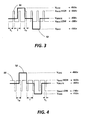
- a waveform 50 depicts the bias voltage for the DAD developer housing 32 of Fig. 2.
- the waveform 50 is superimposed upon a typical tri-level image represented by reference character 52.
- the DAD bias is alternated between two potentials represented by V Bias High and V Bias Low.
- V Bias High equals approximately 6% of the total period, T at a frequency of 5kHz and the period, T L is approximately 94% thereof.
- the DC bias levels for V Bias High and V Bias Low are -650 and -300 volts, respectively.
- the DAD image was recorded at a voltage level of -100 volts while the CAD voltage was at -900 volts with the background at -450 volts.
- the bias voltages V Bias High and V Bias Low are -530 and -150 volts, respectively.
- the waveform 55 representing these biases is inverted with respect to the waveform 50 in the sense that the period, T H for V Bias High is approximately 94% of the total period, T while the period T L for V Bias Low is approximately 6% of the total period T.
- a positive pre-transfer corona discharge member 56 is provided to condition the toner for effective transfer to a substrate using negative corona discharge.
- Transfer station D includes a corona generating device 60 which sprays ions of a suitable polarity onto the backside of sheet 58. This attracts the charged toner powder images from the belt 10 to sheet 58. After transfer, the sheet continues to move, in the direction of arrow 62, onto a conveyor (not shown) which advances the sheet to fusing station E.
- Fusing station E includes a fuser assembly, indicated generally by the reference numeral 64, which permanently affixes the transferred powder image to sheet 58.
- fuser assembly 64 comprises a heated fuser roller 66 and a backup roller 68.
- Sheet 58 passes between fuser roller 66 and backup roller 68 with the toner powder image contacting fuser roller 66. In this manner, the toner powder image is permanently affixed to sheet 58.
- a chute guides the advancing sheet 58 to a catch tray, also not shown, for subsequent removal from the printing machine by the operator.
- the magnetic brush cleaner housing 70 is disposed at the cleaner station F.
- the cleaner apparatus comprises a conventional magnetic brush roll structure for causing carrier particles in the cleaner housing to form a brush-like orientation relative to the roll structure and the charge retentive surface. It also includes a pair of detoning rolls for removing the residual toner from the brush.
- a discharge lamp (not shown) floods the photoconductive surface with light to dissipate any residual electrostatic charge remaining prior to the charging thereof for the successive imaging cycle.
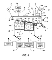
- FIG 5 A modified form of the printing machine of Figure 2 is shown in figure 5.
- components corresponding to those in Figure 2 carry the same reference numerals.
- the machine 9 shown in Figure 5 has two operating modes, namely a tri-level highlight color mode and a bi-level monochrome mode, and to that end it differs from the Figure 2 machine by the addition of a DC power supply 45 and a switch 49 which are associated with the developer housing 34, and a switch 47 which is associated with the developer housing 32.
- the switches 47, 49 are in the position shown in Figure 5 so that the power supply 41 applies a CDC bias to the rolls 35, 36 in developer housing 32, and the power supply 43 applies a CDC bias to the rolls 37, 38 in developer housing 34.
- the machine functions as described with reference to Figure 2. Developer bias switching between V Bias High and V Bias Low is effected automatically via the power supplies 41 and 43 under the control of the ESS 26.
- the switches 47, 49 are moved into the alternative position as indicated by the broken-line arrows. In that position, the bias is removed from the rolls 35, 36 by the switch 47 and the conventional DC bias is applied to the rolls 37, 38 via the standard bias power supply 45 through switch 49.
- the machine shown in Figure 5 also differs from that shown in Figure 2 in that the rolls 37 and 38 and the backup rolls disposed to the other side of the photoreceptor belt 10 are arranged so that the belt is wrapped about the rolls 37, 38. While only two rolls 37 and 38 are contained in the housing 34, the use of three rolls is contemplated.
- the operating latitude of the tri-level xerographic process is improved by replacing the standard DC bias that is applied to one or both of the developer housings in conventional tri-level imaging with a chopped DC (CDC) developer bias. That is, the housing bias applied to the developer housing is alternated between two potentials, one that represents roughly the normal bias for the DAD developer, and the other that represents a bias that is considerably more negative than the normal bias, the former being identified as V Bias Low and the latter as V Bias High.
- CDC chopped DC
- This alternation of the bias takes place in a periodic fashion at a given frequency, with the period of each cycle divided up between the two bias levels at a duty cycle of 6% but which may be within the range of from 5-10 % (Percent of cycle at V BIAS High).
- the amplitude of both V BIAS Low and V BIAS High are about the same as for the DAD housing case, but the waveform is inverted in the sense that the bias on the CAD housing is at V BIAS High for a duty cycle of 94% (but which may be within the range of from 90-95%).
- DMA developed mass/area
- Q/M developed charge/mass
- the increases in the DMA and Q/M when using a Chopped DC bias, and the resultant increase in image neutralization, are used to improve the operating latitude in several different ways.
- the increased developability that is obtained when using the Chopped DC bias instead of an equivalent conventional DC bias can be used to either obtain higher DMA's for the same background level, or to obtain the same DMA as the DC bias case, but with reduced development fields.
- the reduced development fields in the latter case would make available photoreceptor voltage that could be applied elsewhere (i.e: red and black cleaning fields, or reduction of photoreceptor voltages).
- the higher developed Q/M helps to decrease the amount of red image damage caused by the second CAD black housing.
- the increased neutralization helps to prevent the development of black carrier-beads and wrong sign toner into the first (DAD) image by the second (CAD) developer housing.
- the developer biases in a tri-level highlight color printer are switched between standard DC and chopped DC bias modes.
- the standard DC bias mode is used to obtain excellent black copy quality in the black monochrome mode using Insulative Magnetic Brush (IMB) developer.
- the chopped DC bias mode is used to increase the DMA (as already mentioned) and reduce undesirable fringe field development in the black housing when printing in the tri-level highlight color mode.
- tri-level highlight color printing can be achieved in a high speed printer which utilizes a black (IMB) developer by using chopped DC bias (CDC) in the highlight color mode while still preserving the excellent quality monochromatic black images by electrically biasing the black developer housing using a conventional DC bias while operating in a first mode of operation.
- the end result of bias switching in Figure 5 is to produce excellent black copy quality in the black monochrome mode in high speed printing, while both enabling tri-level highlight color and extending the operating latitude in the tri-level highlight color mode.
Landscapes
- Physics & Mathematics (AREA)
- General Physics & Mathematics (AREA)
- Color Electrophotography (AREA)
Applications Claiming Priority (4)
| Application Number | Priority Date | Filing Date | Title |
|---|---|---|---|
| US07/440,914 US5079114A (en) | 1989-11-22 | 1989-11-22 | Biasing switching between tri-level and bi-level development |
| US07/440,913 US5080988A (en) | 1989-11-22 | 1989-11-22 | Biasing scheme for improving latitudes in the tri-level xerographic process |
| US440913 | 1989-11-22 | ||
| US440914 | 1989-11-22 |
Publications (3)
| Publication Number | Publication Date |
|---|---|
| EP0429309A2 true EP0429309A2 (de) | 1991-05-29 |
| EP0429309A3 EP0429309A3 (en) | 1991-11-06 |
| EP0429309B1 EP0429309B1 (de) | 1994-12-14 |
Family
ID=27032602
Family Applications (1)
| Application Number | Title | Priority Date | Filing Date |
|---|---|---|---|
| EP90312719A Expired - Lifetime EP0429309B1 (de) | 1989-11-22 | 1990-11-22 | Polarisierungsweise zur Verbesserung der Eigenschaften der Drei-Niveau-Xerographie |
Country Status (2)
| Country | Link |
|---|---|
| EP (1) | EP0429309B1 (de) |
| DE (1) | DE69015131T2 (de) |
Cited By (1)
| Publication number | Priority date | Publication date | Assignee | Title |
|---|---|---|---|---|
| EP0531053A3 (en) * | 1991-09-05 | 1994-09-21 | Xerox Corp | Tri-level imaging apparatus |
Family Cites Families (3)
| Publication number | Priority date | Publication date | Assignee | Title |
|---|---|---|---|---|
| GB2145942B (en) * | 1983-08-05 | 1987-03-18 | Konishiroku Photo Ind | Developing latent eletrostatic images |
| US4847655A (en) * | 1987-12-11 | 1989-07-11 | Xerox Corporation | Highlight color imaging apparatus |
| US5066979A (en) * | 1989-01-13 | 1991-11-19 | Canon Kabushiki Kaisha | Color image forming apparatus wherein plural colors can be formed through one printing cycle |
-
1990
- 1990-11-22 DE DE69015131T patent/DE69015131T2/de not_active Expired - Fee Related
- 1990-11-22 EP EP90312719A patent/EP0429309B1/de not_active Expired - Lifetime
Cited By (1)
| Publication number | Priority date | Publication date | Assignee | Title |
|---|---|---|---|---|
| EP0531053A3 (en) * | 1991-09-05 | 1994-09-21 | Xerox Corp | Tri-level imaging apparatus |
Also Published As
| Publication number | Publication date |
|---|---|
| DE69015131D1 (de) | 1995-01-26 |
| EP0429309B1 (de) | 1994-12-14 |
| EP0429309A3 (en) | 1991-11-06 |
| DE69015131T2 (de) | 1995-07-27 |
Similar Documents
| Publication | Publication Date | Title |
|---|---|---|
| US4847655A (en) | Highlight color imaging apparatus | |
| EP0305222B1 (de) | Verfahren und Vorrichtung zur Magnetbürstenentwicklung | |
| US4731634A (en) | Apparatus for printing black and plural highlight color images in a single pass | |
| US4771314A (en) | Developer apparatus for a highlight printing apparatus | |
| JP2809410B2 (ja) | ハイライトカラーイメージング装置 | |
| US5031570A (en) | Printing apparatus and toner/developer delivery system therefor | |
| US4761672A (en) | Ramped developer biases | |
| US5337136A (en) | Tandem trilevel process color printer | |
| US5021838A (en) | Preferred toner/carrier properties | |
| US5061969A (en) | Hybrid development scheme for trilevel xerography | |
| EP0465211B1 (de) | Druckgerät mit Hervorhebung der Farben | |
| US5038177A (en) | Selective pre-transfer corona transfer with light treatment for tri-level xerography | |
| US5080988A (en) | Biasing scheme for improving latitudes in the tri-level xerographic process | |
| US4984021A (en) | Photoreceptor edge erase system for tri-level xerography | |
| US5583629A (en) | Color electrophotographic printing machine | |
| US5241359A (en) | Biasing switching between tri-level and bi-level development | |
| US4761668A (en) | Highlight color printer | |
| US4959286A (en) | Two-pass highlight color imaging with developer housing bias switching | |
| US5241358A (en) | Biasing scheme for improving latitudes in the tri-level xerographic process | |
| EP0361851B1 (de) | Photorezeptorrandlöschsystem, insbesondere für Dreistufenxerographie | |
| US5480751A (en) | Tri-level background suppression scheme using an AC scorotron with front erase | |
| US5539506A (en) | Edge raggedness and background removal by post development member | |
| EP0429309B1 (de) | Polarisierungsweise zur Verbesserung der Eigenschaften der Drei-Niveau-Xerographie | |
| CA2027459C (en) | Bias switching between tri-level and bi-level development | |
| EP0588552B1 (de) | Verfahren und Gerät zum Aufladen einer photoleitenden Oberfläche mit einem gleichmässigen Potential |
Legal Events
| Date | Code | Title | Description |
|---|---|---|---|
| PUAI | Public reference made under article 153(3) epc to a published international application that has entered the european phase |
Free format text: ORIGINAL CODE: 0009012 |
|
| AK | Designated contracting states |
Kind code of ref document: A2 Designated state(s): DE FR GB |
|
| PUAL | Search report despatched |
Free format text: ORIGINAL CODE: 0009013 |
|
| AK | Designated contracting states |
Kind code of ref document: A3 Designated state(s): DE FR GB |
|
| 17P | Request for examination filed |
Effective date: 19920429 |
|
| 17Q | First examination report despatched |
Effective date: 19930524 |
|
| GRAA | (expected) grant |
Free format text: ORIGINAL CODE: 0009210 |
|
| AK | Designated contracting states |
Kind code of ref document: B1 Designated state(s): DE FR GB |
|
| REF | Corresponds to: |
Ref document number: 69015131 Country of ref document: DE Date of ref document: 19950126 |
|
| ET | Fr: translation filed | ||
| PLBE | No opposition filed within time limit |
Free format text: ORIGINAL CODE: 0009261 |
|
| STAA | Information on the status of an ep patent application or granted ep patent |
Free format text: STATUS: NO OPPOSITION FILED WITHIN TIME LIMIT |
|
| 26N | No opposition filed | ||
| REG | Reference to a national code |
Ref country code: GB Ref legal event code: IF02 |
|
| PGFP | Annual fee paid to national office [announced via postgrant information from national office to epo] |
Ref country code: FR Payment date: 20031110 Year of fee payment: 14 |
|
| PGFP | Annual fee paid to national office [announced via postgrant information from national office to epo] |
Ref country code: GB Payment date: 20031119 Year of fee payment: 14 |
|
| PGFP | Annual fee paid to national office [announced via postgrant information from national office to epo] |
Ref country code: DE Payment date: 20031204 Year of fee payment: 14 |
|
| PG25 | Lapsed in a contracting state [announced via postgrant information from national office to epo] |
Ref country code: GB Free format text: LAPSE BECAUSE OF NON-PAYMENT OF DUE FEES Effective date: 20041122 |
|
| PG25 | Lapsed in a contracting state [announced via postgrant information from national office to epo] |
Ref country code: DE Free format text: LAPSE BECAUSE OF NON-PAYMENT OF DUE FEES Effective date: 20050601 |
|
| GBPC | Gb: european patent ceased through non-payment of renewal fee |
Effective date: 20041122 |
|
| PG25 | Lapsed in a contracting state [announced via postgrant information from national office to epo] |
Ref country code: FR Free format text: LAPSE BECAUSE OF NON-PAYMENT OF DUE FEES Effective date: 20050729 |
|
| REG | Reference to a national code |
Ref country code: FR Ref legal event code: ST |