EP0429332B1 - Verfahren und Anordnung zur Bestimmung der Charakteristiken einer Linse, insbesondere ihrer Stärke - Google Patents
Verfahren und Anordnung zur Bestimmung der Charakteristiken einer Linse, insbesondere ihrer Stärke Download PDFInfo
- Publication number
- EP0429332B1 EP0429332B1 EP90403167A EP90403167A EP0429332B1 EP 0429332 B1 EP0429332 B1 EP 0429332B1 EP 90403167 A EP90403167 A EP 90403167A EP 90403167 A EP90403167 A EP 90403167A EP 0429332 B1 EP0429332 B1 EP 0429332B1
- Authority
- EP
- European Patent Office
- Prior art keywords
- lens
- light
- axis
- determination
- position sensor
- Prior art date
- Legal status (The legal status is an assumption and is not a legal conclusion. Google has not performed a legal analysis and makes no representation as to the accuracy of the status listed.)
- Expired - Lifetime
Links
- 238000000034 method Methods 0.000 title claims description 6
- 230000003287 optical effect Effects 0.000 claims description 14
- 238000004458 analytical method Methods 0.000 claims description 8
- 230000005540 biological transmission Effects 0.000 claims description 8
- 230000015572 biosynthetic process Effects 0.000 claims description 7
- 238000011084 recovery Methods 0.000 claims 1
- 238000012545 processing Methods 0.000 description 10
- 238000010586 diagram Methods 0.000 description 7
- 239000013307 optical fiber Substances 0.000 description 6
- 238000005259 measurement Methods 0.000 description 5
- 238000011144 upstream manufacturing Methods 0.000 description 5
- 230000003321 amplification Effects 0.000 description 3
- 238000006243 chemical reaction Methods 0.000 description 3
- 238000003199 nucleic acid amplification method Methods 0.000 description 3
- 238000011161 development Methods 0.000 description 2
- 230000018109 developmental process Effects 0.000 description 2
- 239000000470 constituent Substances 0.000 description 1
- 230000004907 flux Effects 0.000 description 1
- 230000032696 parturition Effects 0.000 description 1
- 238000012360 testing method Methods 0.000 description 1
Images

Classifications
-
- G—PHYSICS
- G01—MEASURING; TESTING
- G01M—TESTING STATIC OR DYNAMIC BALANCE OF MACHINES OR STRUCTURES; TESTING OF STRUCTURES OR APPARATUS, NOT OTHERWISE PROVIDED FOR
- G01M11/00—Testing of optical apparatus; Testing structures by optical methods not otherwise provided for
- G01M11/02—Testing optical properties
- G01M11/0228—Testing optical properties by measuring refractive power
Definitions
- the present invention relates generally to the determination of at least some of the optical characteristics of a lens.
- It relates more particularly, but not exclusively, to the determination of the focal power of an ophthalmic lens.
- This determination is usually made using a device, or instrument, commonly called a frontofocometer.
- the present invention relates, more particularly still, to the case where such a device comprises, in practice upstream of the lens, emission means suitable for the formation of a plurality of light beams, and, downstream of the latter , a photosensitive position sensor capable of allowing the reading of the impact of this light beam in an analysis plane perpendicular to the axis of the lens after passing through it.
- the present invention is based on the observation, not demonstrated to date, that it was advantageously possible to simplify this operation by taking into consideration a central light ray.
- the present invention thus firstly relates to a method for determining at least one of the characteristics of a lens, of the kind according to which, as regards the determination of its focal power, this lens is passed through by at least three light rays distributed in a circle around the axis of said lens and there is a photosensitive position sensor downstream of said lens capable of enabling the coordinates of their impacts to be recorded in an analysis plane perpendicular to the axis of the lens, this method being generally characterized in that one chooses, for light rays, in addition to the three light rays distributed in a circle, a light ray passing through the axis of the lens; it also relates to a device specific to the implementation of such a method.
- the use of a central light ray makes it possible to simplify the processing of the signals obtained, it also makes it possible, advantageously, to determine, before each measurement, the center of coordinates to be taken into account, to properly center the lens to be studied, by analyzing the impact of the central light ray after crossing it, and to have a direct measurement of the prism that this lens may possibly present.
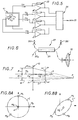
- FIG. 1 it is a question, overall, of measuring the focal power of an ophthalmic lens 10, and, for example, as shown, of a converging ophthalmic lens.
- It can be both a spherical only ophthalmic lens and an ophthalmic lens spherocylindrical.
- the device used to measure the focal power of such an ophthalmic lens 10 comprises, upstream of this ophthalmic lens 10, emission means 11 suitable for the formation of a plurality of light rays M, and, downstream of the latter, a position sensor 12 capable of enabling the coordinates of their impacts M 'to be recorded in an analysis plane P perpendicular to the axis A of the assembly, this analysis plane P being by example formed by the front face of such a position sensor 12.
- the light rays M have been shown to be relatively thick in FIGS. 1 to 3 and in the diagram in FIG. 8A.
- a processing unit 13 suitable for processing the signals it delivers and, preferably, for automatic processing of these signals.
- the emission means 11 are chosen so as to be suitable for the formation of three light rays M1, M2, M3 distributed along the same circle C, by example at 135 ° two by two for the light rays M1, M3, on the one hand, and M2, M3, on the other hand, and at 90 ° with respect to each other for the light rays M1, M2 , as shown, and a central light beam M o , that is to say a light ray passing through the axis of the assembly.
- the emission means 11 comprise a light source 15, a collimator 16, and a screen 17 pierced with holes 18, at the rate of one per light ray M.
- the emitting means 11 may comprise a bundle of four optical fibers 20 o , 201, 202, 203, the ends of which, duly provided with collimating optics, such as a ball or microlens by example, are distributed according to the desired arrangement, namely, as indicated above, a circle C, for the formation of the light rays M1, M2, M3, and the axis of the assembly for the formation of the light ray M o central.
- collimating optics such as a ball or microlens by example
- these optical fibers 20 o , 201, 202, 203 are served by a light distribution box 21 which is common to them.
- an individual light source such as a light-emitting diode, laser or lamp for example.
- the device according to the invention comprises a cover 22 adapted to allow only one light ray M to pass at a time.
- this cover 22 operates downstream of the transmission means 11.
- optical fibers 20 o , 201, 202, 203 for the constitution of these, it can intervene within these emission means 11, between the source luminous serving these optical fibers 20 o , 201, 202, 203 and the entry thereof.
- the position sensor 12 is followed by a voltage current conversion and amplification stage 23, then by an analog-to-digital converter 24, before the signals which it delivers are applied to computer means. treatment 25.
- this position sensor 12 is a sensor capable of delivering a signal proportional to the intensity of the light ray which it receives.
- a photosensitive surface which, in response to the impact of a light ray M, is capable of generating electric currents ix1, ix2, iy1, iy2 according to each of the four directions of the plane, two corresponding to the x- axis and the other two to the y- axis.
- the intensity of each of these currents is proportional to the light intensity.
- the current voltage and amplification conversion stage 23 has as many constituents as there are plane directions.
- the refractive index of the ophthalmic lens 10 it is also associated, with the central light ray M o of the emission means 11, means 27 suitable for recovering the ray reflected on the ophthalmic lens 10 and to send it to a detector 28r capable of delivering a signal linked to its light intensity.
- the transmission means 11 are then transmission means with optical fibers.
- central optical fiber 20 o which is used, in cooperation with an X-coupler 29, making it possible, on the one hand, to direct half of the intensity which it carries towards a detector 28i, and, d on the other hand, recover the reflected light ray and direct half of its intensity towards the detector 28r.
- the detectors 28r and 28i operate upstream of the voltage current conversion and amplification stage 23, in parallel with the position sensor 12.
- this axis A ' has been assumed to coincide with the axis A of the emission means 11 and of the position sensor 12.
- the central light ray M o strikes the lens at a point m o , and, after crossing the latter, it is deflected towards its focal point F.
- the calculation makes it possible to determine the coordinates x ' o , y' o of the point m ' o as a function of those x o , y o of the point m o , of the distance D between the mean plane of the ophthalmic lens 10 and the plane d 'analysis P, and of the offset of the axis A' of this ophthalmic lens 10 relative to the axis A of the entire device.
- this curve is a circle.
- this curve is, as shown diagrammatically in FIG. 8B, an ellipse C '.
- the calculation shows that it is therefore possible to determine the focal power of the ophthalmic lens 10 as a function of the major axis and the minor axis of this ellipse.
- the refractive index n of the ophthalmic lens 10 is obtained by the reflectance coefficient, that is to say by the ratio Re between the intensity Ir of the reflected light ray and that Ii of the incident light ray, as noted using detectors 28r and 28i.
- the optical transmission of the ophthalmic lens 10 is obtained by the ratio between the light fluxes detected with and without this ophthalmic lens 10.
Landscapes
- Chemical & Material Sciences (AREA)
- Analytical Chemistry (AREA)
- Physics & Mathematics (AREA)
- General Physics & Mathematics (AREA)
- Testing Of Optical Devices Or Fibers (AREA)
- Eyeglasses (AREA)
Claims (6)
- Verfahren zur Bestimmung von zumindest einem der Merkmale einer Linse (10), derart, daß, wenn es sich um die Bestimmung ihrer Brechkraft handelt, man durch diese Linse (10) zumindest drei Lichtstrahlen (M₁, M₂, M₃) schickt, die gemäß einem Kreis (C) um die Achse (A) der Linse (10) verteilt sind, und man hinter der Linse (10) einen strahlungsempfindlichen Positionsfühler (12) anordnet, der geeignet ist, die Ermittlung der Koordinaten ihres Auftreffens in einer Analysenebene (P) zu ermoglichen, die senkrecht zur Achse der Linse (10) liegt, dadurch gekennzeichnet, daß man als Lichtstrahlen (M), außer den gemäß einem Kreis (C) verteilten drei Lichtstrahlen, einen Lichtstrahl wählt, der durch die Achse (A) der Linse (10) läuft.
- Vorrichtung zur Bestimmung der Merkmale einer Linse, derart, daß sie Aussendemittel (11) zur Bildung von zumindest drei Lichtstrahlen (M₁, M₂, M₃) aufweist, die gemäß einem Kreis (C) um die Achse (A) der Linse (10) verteilt sind, und einen Positionsfühler (12), der geeignet ist, die Ermittlung der Koordinaten ihres Auftreffens in einer Analysenebene (P), die senkrecht zur Achse (A) des Ganzen liegt, zu ermöglichen, dadurch gekennzeichnet, daß zum Einsatz eines Verfahrens gemäß Anspruch 1 die Aussendemittel (11) geeignet sind, außer den drei Lichtstrahlen (M₁, M₂ , M₃), die gemäß einem Kreis (C) verteilt sind, den Lichtstrahl (Mo), der durch die Achse (A) der Linse (10) lauft, zu bilden.
- Vorrichtung gemäß Anspruch 2, dadurch gekennzeichnet, daß sie eine Abdeckung (22) aufweist, die nur einen einzigen Lichtstrahl (M) zur Zeit durchläßt.
- Vorrichtung gemäß irgendeinem der Ansprüche 2, 3, dadurch gekennzeichnet, daß der Positionsfühler (12) dazu geeignet ist, elektrische Ströme (ix₁, ix₂, iy₁, iy₂) gemäß jeder der vier Richtungen der Ebene zu erzeugen, und zwar zwei entsprechend der Abszissenachse (x) und die anderen beiden entsprechend der Ordinatenachse (y)
- Vorrichtung gemäß irgendeinem der Ansprüche 2 bis 4, dadurch gekennzeichnet, daß der strahlenempfindliche Positionsfühler (12) zur Bestimmung der optischen Transmission der Linse (10) ein Fühler ist, der geeignet ist, ein Signal proportional zur Intensitat des Lichtstrahles, den er empfängt, zu liefern.
- Vorrichtung gemäß irgendeinem der Ansprüche 2 bis 5, dadurch gekennzeichnet, daß zur Bestimmung des Brechungsindex der Linse (10) an dem zentralen Lichtstrahl (Mo) seiner Aussendemittel (11) Mittel (27) angeschlossen sind, die dazu geeignet sind, den auf der Linse (10) reflektierten Strahl einzufangen und ihn zu einem Detektor (28r) zu senden, der geeignet ist, ein Signal, das an seine Lichtintensität gebunden ist, zu liefern.
Applications Claiming Priority (2)
| Application Number | Priority Date | Filing Date | Title |
|---|---|---|---|
| FR8914782 | 1989-11-10 | ||
| FR8914782A FR2654513B1 (fr) | 1989-11-10 | 1989-11-10 | Procede et dispositif pour la determiantion des caracteristiques d'un lentille, et, notamment, de sa puissance. |
Publications (2)
| Publication Number | Publication Date |
|---|---|
| EP0429332A1 EP0429332A1 (de) | 1991-05-29 |
| EP0429332B1 true EP0429332B1 (de) | 1994-01-26 |
Family
ID=9387290
Family Applications (1)
| Application Number | Title | Priority Date | Filing Date |
|---|---|---|---|
| EP90403167A Expired - Lifetime EP0429332B1 (de) | 1989-11-10 | 1990-11-07 | Verfahren und Anordnung zur Bestimmung der Charakteristiken einer Linse, insbesondere ihrer Stärke |
Country Status (6)
| Country | Link |
|---|---|
| US (1) | US5108174A (de) |
| EP (1) | EP0429332B1 (de) |
| JP (1) | JPH0827218B2 (de) |
| DE (1) | DE69006326T2 (de) |
| ES (1) | ES2050979T3 (de) |
| FR (1) | FR2654513B1 (de) |
Families Citing this family (10)
| Publication number | Priority date | Publication date | Assignee | Title |
|---|---|---|---|---|
| US5331394A (en) * | 1992-04-10 | 1994-07-19 | Metaphase Corporation | Automated lensometer |
| US5953114A (en) * | 1994-04-11 | 1999-09-14 | Leica Mikroskopie Systeme Ag | Method of determining measurement-point position data and device for measuring the magnification of an optical beam path |
| WO1995034800A1 (en) * | 1994-06-14 | 1995-12-21 | Visionix Ltd. | Apparatus for mapping optical elements |
| US5523836A (en) * | 1994-11-02 | 1996-06-04 | Minix; Marcus S. | Method and apparatus for orienting a lens' refractive characteristics and lay-out properties |
| JP3814155B2 (ja) * | 2001-03-14 | 2006-08-23 | Hoya株式会社 | 透過率測定方法及び装置 |
| US6561648B2 (en) * | 2001-05-23 | 2003-05-13 | David E. Thomas | System and method for reconstruction of aberrated wavefronts |
| TWI244861B (en) * | 2004-07-06 | 2005-12-01 | Asia Optical Co Inc | Device and method for optical center detection |
| CN100428049C (zh) * | 2004-07-21 | 2008-10-22 | 亚洲光学股份有限公司 | 光学中心监测装置及方法 |
| CN111670350B (zh) * | 2017-12-28 | 2022-06-10 | 光学转变有限公司 | 用于测量隐形眼镜的光学特性的方法和系统 |
| US10859494B2 (en) * | 2018-09-03 | 2020-12-08 | Chongqing Hkc Optoelectronics Technology Co., Ltd. | Transmittance measuring method, device and computer readable storage medium |
Family Cites Families (11)
| Publication number | Priority date | Publication date | Assignee | Title |
|---|---|---|---|---|
| US3880525A (en) * | 1974-05-08 | 1975-04-29 | American Optical Corp | Method and apparatus for determining the refractive characteristics of a lens |
| US4275964A (en) * | 1979-05-18 | 1981-06-30 | Rodenstock Instruments Corporation | Apparatus and method for determining the refractive characteristics of a test lens |
| DE3208024A1 (de) * | 1981-03-05 | 1982-11-04 | Tokyo Kogaku Kikai K.K., Tokyo | Linsenpruefgeraet |
| JPS58737A (ja) * | 1981-06-26 | 1983-01-05 | Nippon Kogaku Kk <Nikon> | 自動レンズメ−タ |
| JPS60442B2 (ja) * | 1981-11-28 | 1985-01-08 | 株式会社サンリツト産業 | 被服 |
| US4609287A (en) * | 1982-10-05 | 1986-09-02 | Canon Kabushiki Kaisha | Method of and apparatus for measuring refractive characteristics |
| JPS5964022A (ja) * | 1982-10-05 | 1984-04-11 | キヤノン株式会社 | 屈折度測定装置 |
| US4826315A (en) * | 1985-06-14 | 1989-05-02 | Canon Kabushiki Kaisha | Lens meter |
| SU1420428A1 (ru) * | 1986-12-16 | 1988-08-30 | Предприятие П/Я А-1705 | Устройство дл контрол качества изображени оптических систем |
| JPH0752568Y2 (ja) * | 1987-10-29 | 1995-11-29 | 鐘淵化学工業株式会社 | 位置検出装置 |
| JP2768955B2 (ja) * | 1988-09-05 | 1998-06-25 | 株式会社トプコン | レンズメータ |
-
1989
- 1989-11-10 FR FR8914782A patent/FR2654513B1/fr not_active Expired - Fee Related
-
1990
- 1990-10-23 US US07/601,434 patent/US5108174A/en not_active Expired - Fee Related
- 1990-11-07 DE DE90403167T patent/DE69006326T2/de not_active Expired - Fee Related
- 1990-11-07 ES ES90403167T patent/ES2050979T3/es not_active Expired - Lifetime
- 1990-11-07 JP JP2302327A patent/JPH0827218B2/ja not_active Expired - Lifetime
- 1990-11-07 EP EP90403167A patent/EP0429332B1/de not_active Expired - Lifetime
Also Published As
| Publication number | Publication date |
|---|---|
| FR2654513A1 (fr) | 1991-05-17 |
| JPH03172729A (ja) | 1991-07-26 |
| ES2050979T3 (es) | 1994-06-01 |
| DE69006326D1 (de) | 1994-03-10 |
| FR2654513B1 (fr) | 1993-07-16 |
| DE69006326T2 (de) | 1994-05-05 |
| US5108174A (en) | 1992-04-28 |
| EP0429332A1 (de) | 1991-05-29 |
| JPH0827218B2 (ja) | 1996-03-21 |
Similar Documents
| Publication | Publication Date | Title |
|---|---|---|
| EP0278882B1 (de) | Verfahren und Vorrichtung zum Erstellen eines Abdrucks für medizinische Zwecke | |
| EP0429332B1 (de) | Verfahren und Anordnung zur Bestimmung der Charakteristiken einer Linse, insbesondere ihrer Stärke | |
| EP0604276A1 (de) | Verfahren und Vorrichtung zur Bestimmung der Farbe eines durchsichtigen streuenden und absorbierenden Gegenstandes, i.B. eines Zahns | |
| RU2670809C2 (ru) | Устройство измерения шероховатости поверхности | |
| FR2508160A1 (fr) | Dispositif pour determiner la position d'un objet | |
| EP1183518B1 (de) | Vorrichtung zur bestimmung der werte mindestens eines teilchenparameters, insbesondere von wassertröpfchen | |
| FR2487077A1 (fr) | Dispositif de determination a distance de la position dans l'espace d'un objet effectuant des mouvements de rotation | |
| CA2517252A1 (fr) | Detection de la carie interproximale a l'aide d'une sonde optique examinant la surface occlusale de la dent | |
| CH646516A5 (fr) | Procede et dispositif de mesure du profil transversal du champignon d'un rail d'une voie ferree. | |
| EP0512919A1 (de) | Vorrichtung zur Fernmessung der Position eines Gegenstandes | |
| CN102183359B (zh) | 对光束的准直性进行检测的方法和装置 | |
| FR2559577A1 (fr) | Procede de mesure par trace polygonal et dispositif de mesure | |
| EP1240496A1 (de) | Vorrichtung zur messung durch beugung der grösse von im wesentlichen sphärischen teilchen, insbesondere undurchsichtigen tropfen | |
| FR2639124A1 (fr) | Velocimetre doppler optique a faisceau de reference pour des mesures multidimensionnelles | |
| FR2749388A1 (fr) | Appareil de mesure des caracteristiques photometriques et colorimetriques d'un objet | |
| EP3111188B1 (de) | Optisches instrument zur identifizierung und lokalisierung von mikroätzung auf einer ophthalmischen linse | |
| EP0610640B1 (de) | Tragbarer Strichmarkierungsleser mit erweiterter Schärfentiefe | |
| FR2542878A1 (fr) | Dispositif de balayage | |
| EP0347298B1 (de) | Verfahren und Vorrichtung zur Messung der Sichtweite durch ein Medium veränderlicher Dichte | |
| EP0522951B1 (de) | Vorrichtung zur berührungslosen Messung des im wesentlichen zylindrischen Durchmessers eines Objektes, zum Beispiel einer optischen Faser | |
| EP1105712B1 (de) | Messvorrichtung der grösse sich bewegender teilchen, insbesondere für regenmessungen | |
| WO1991012490A1 (fr) | Procede et dispositif pour mesurer la torsion d'un fil textile | |
| EP4526621A1 (de) | Chromatische konfokale messvorrichtung mit einer kamera | |
| EP1077641B1 (de) | Kompakter optischer sensor fuer digitalen fingerabdruck | |
| EP0277877A2 (de) | Geschwindigkeitsmesser mit Mosaik aus Lichtleitfasern |
Legal Events
| Date | Code | Title | Description |
|---|---|---|---|
| PUAI | Public reference made under article 153(3) epc to a published international application that has entered the european phase |
Free format text: ORIGINAL CODE: 0009012 |
|
| AK | Designated contracting states |
Kind code of ref document: A1 Designated state(s): DE ES GB IT |
|
| 17P | Request for examination filed |
Effective date: 19910424 |
|
| 17Q | First examination report despatched |
Effective date: 19920714 |
|
| GRAA | (expected) grant |
Free format text: ORIGINAL CODE: 0009210 |
|
| AK | Designated contracting states |
Kind code of ref document: B1 Designated state(s): DE ES GB IT |
|
| GBT | Gb: translation of ep patent filed (gb section 77(6)(a)/1977) |
Effective date: 19940125 |
|
| REF | Corresponds to: |
Ref document number: 69006326 Country of ref document: DE Date of ref document: 19940310 |
|
| ITF | It: translation for a ep patent filed | ||
| REG | Reference to a national code |
Ref country code: ES Ref legal event code: FG2A Ref document number: 2050979 Country of ref document: ES Kind code of ref document: T3 |
|
| PLBE | No opposition filed within time limit |
Free format text: ORIGINAL CODE: 0009261 |
|
| STAA | Information on the status of an ep patent application or granted ep patent |
Free format text: STATUS: NO OPPOSITION FILED WITHIN TIME LIMIT |
|
| 26N | No opposition filed | ||
| PGFP | Annual fee paid to national office [announced via postgrant information from national office to epo] |
Ref country code: ES Payment date: 20001113 Year of fee payment: 11 |
|
| PG25 | Lapsed in a contracting state [announced via postgrant information from national office to epo] |
Ref country code: ES Free format text: LAPSE BECAUSE OF NON-PAYMENT OF DUE FEES Effective date: 20011108 |
|
| REG | Reference to a national code |
Ref country code: GB Ref legal event code: IF02 |
|
| PGFP | Annual fee paid to national office [announced via postgrant information from national office to epo] |
Ref country code: GB Payment date: 20031031 Year of fee payment: 14 |
|
| PGFP | Annual fee paid to national office [announced via postgrant information from national office to epo] |
Ref country code: DE Payment date: 20040129 Year of fee payment: 14 |
|
| REG | Reference to a national code |
Ref country code: ES Ref legal event code: FD2A Effective date: 20021213 |
|
| PG25 | Lapsed in a contracting state [announced via postgrant information from national office to epo] |
Ref country code: GB Free format text: LAPSE BECAUSE OF NON-PAYMENT OF DUE FEES Effective date: 20041107 |
|
| PG25 | Lapsed in a contracting state [announced via postgrant information from national office to epo] |
Ref country code: DE Free format text: LAPSE BECAUSE OF NON-PAYMENT OF DUE FEES Effective date: 20050601 |
|
| GBPC | Gb: european patent ceased through non-payment of renewal fee |
Effective date: 20041107 |
|
| PG25 | Lapsed in a contracting state [announced via postgrant information from national office to epo] |
Ref country code: IT Free format text: LAPSE BECAUSE OF NON-PAYMENT OF DUE FEES;WARNING: LAPSES OF ITALIAN PATENTS WITH EFFECTIVE DATE BEFORE 2007 MAY HAVE OCCURRED AT ANY TIME BEFORE 2007. THE CORRECT EFFECTIVE DATE MAY BE DIFFERENT FROM THE ONE RECORDED. Effective date: 20051107 |