EP0429339B1 - Befestigungsvorrichtung, bestehend aus Kabeln oder Stangen - Google Patents
Befestigungsvorrichtung, bestehend aus Kabeln oder Stangen Download PDFInfo
- Publication number
- EP0429339B1 EP0429339B1 EP90403215A EP90403215A EP0429339B1 EP 0429339 B1 EP0429339 B1 EP 0429339B1 EP 90403215 A EP90403215 A EP 90403215A EP 90403215 A EP90403215 A EP 90403215A EP 0429339 B1 EP0429339 B1 EP 0429339B1
- Authority
- EP
- European Patent Office
- Prior art keywords
- wall
- elongate element
- cables
- strut
- elongate
- Prior art date
- Legal status (The legal status is an assumption and is not a legal conclusion. Google has not performed a legal analysis and makes no representation as to the accuracy of the status listed.)
- Expired - Lifetime
Links
Images


Classifications
-
- A—HUMAN NECESSITIES
- A47—FURNITURE; DOMESTIC ARTICLES OR APPLIANCES; COFFEE MILLS; SPICE MILLS; SUCTION CLEANERS IN GENERAL
- A47B—TABLES; DESKS; OFFICE FURNITURE; CABINETS; DRAWERS; GENERAL DETAILS OF FURNITURE
- A47B96/00—Details of cabinets, racks or shelf units not covered by a single one of groups A47B43/00 - A47B95/00; General details of furniture
- A47B96/06—Brackets or similar supporting means for cabinets, racks or shelves
-
- A—HUMAN NECESSITIES
- A47—FURNITURE; DOMESTIC ARTICLES OR APPLIANCES; COFFEE MILLS; SPICE MILLS; SUCTION CLEANERS IN GENERAL
- A47B—TABLES; DESKS; OFFICE FURNITURE; CABINETS; DRAWERS; GENERAL DETAILS OF FURNITURE
- A47B43/00—Cabinets, racks or shelf units, characterised by features enabling folding of the cabinet or the like
- A47B43/003—Suspended shelves, e.g. by means of supple elements
- A47B43/006—Suspended shelves, e.g. by means of supple elements fixed on cords, cables, wire or chains
Definitions
- the invention relates to a device for the removable and adjustable fixing of shelves or other objects, according to the preamble of claim 1.
- Such a device is described for example in FR-A-2 272 627, the elongated elements being cables, and in FR-A-2 407 691, the elongated elements being rods.
- the elongated elements are anchored by their two ends respectively to the ceiling and to the ground, and extend vertically between the ceiling and the ground.
- the object of the invention is to provide a solution to this problem.
- FR-A-2 458 246 and EP-A-0 004 517 describe devices hung on a wall and comprising cables having vertical regions on which shelves can be mounted at an adjustable height.
- the height adjustment is no longer possible after the cables have been laid.
- the vertical regions of the cables and the shelves are only suspended and are not fixed stably.
- the invention relates to a device as defined in claim 1.
- Figure 1 shows a cable device allowing the attachment of several shelves P1 in superimposed positions. It comprises two first cables C11, the upper end of which is anchored in a vertical wall M by means of anchoring parts AM and the lower end of which is anchored to the ground S by means of anchoring parts AS. At a level between that of the anchoring pieces AM and that of the shelves P1, the cables C11 are supported at the free ends of bars or spacers E fixed to the wall by their opposite ends and extending substantially perpendicular to the wall. Each first cable C11 extends vertically between its bearing area on the end of the corresponding spacer and the anchoring piece AS, and obliquely, at an angle to the vertical which does not exceed 45 °, between this support area and the AM anchor.
- Two second cables C21 extend vertically downwards from the two spacers E respectively, between the wall and the bearing area of the first cables C11, to the ground where their lower end is anchored by means of anchoring pieces AS identical to those of the first C11 cables.
- the cables C11 and C21 are tensioned by means of springs integrated into the anchoring parts AS, which can be as described in FR-A-2 272 627.
- Each pair of cables C11-C21 is situated in a vertical plane perpendicular to the wall M, the two planes respectively containing the two pairs of cables being spaced in the longitudinal direction of the wall by a distance corresponding substantially to the length of the shelves P1.
- Each shelf is fixed at each of its ends by two hanging pieces QP removably and adjustable mounted on cables C11 and C21 respectively.
- the parts QP are as described in FR-A-2 627 241 in relation to FIG. 4 of this document. Of course, other types of attachment pieces can be used depending on the thickness and the material of the shelves.
- FIG. 2 illustrates a device on which are hung a shelf P1 similar to those of FIG. 1 and a box R1 having on its front face pivoting doors 1.
- This device comprises two first cables C12 whose upper ends are anchored to the wall M by means of anchoring pieces AM similar to those of FIG. 1, and resting on upper spacers E also similar to those of FIG. 1.
- the lower ends of the cables C12 unlike those of the cables C11 of the figure 1, are also anchored to the wall by means of AM anchoring pieces similar to the preceding ones, and these cables are supported, at an intermediate level between the objects hooked P1 and R1 on the one hand, and the lower anchoring pieces AM on the other hand, on the free ends of lower spacers E similar to the previous ones.
- Each cable C12 extends vertically between the ends of the upper and lower spacers, and obliquely, at angles to the vertical not exceeding 45 °, between the spacers and the corresponding anchoring parts.
- Each of the first two cables C12 is associated with a second cable C22 stretched vertically between the upper and lower spacers E, to which it is linked at intermediate points between the wall and the bearing area of the first cable.
- the tension of each of the cables C12 and C22 is provided by a tensioner TC.
- the cable tensioners C22 are interposed between objects P1 and R1 on the one hand, and the lower spacer on the other hand.
- Those of the cables C12 are interposed, in the example illustrated, between the lower spacer and the lower anchoring part. They could also be between the hanging objects and the lower spacer.
- the shelf P1 is arranged with respect to the cables in the same way as those of FIG. 1, and is hung thereon by pieces QP also similar to those of FIG. 1.
- the two pairs of cables C12-C22 pass opposite the two end faces of the box R1 respectively.
- the latter is linked to each of the four cables, in a removable and adjustable manner, by two QR hooking pieces, superimposed in the direction of the cable, which are as described in FR-A-2 272 627 in relation to FIGS. 4 to 6 of this document, and which receive in their blind hole a cylindrical stud projecting from the end face of the box.
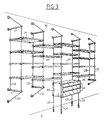
- FIG. 3 represents a mixed device comprising both cables with lower anchoring to the ground and cables with lower anchoring to the wall.
- a series of superimposed shelves P1 as described above.
- a box R2 provided with drawers 2 is mounted between the two pairs of cables C11-C21, in the manner described above with regard to the box R1.
- FIG. 4 shows an AM wall anchor and the upper end of the cable C11 or C12 attached to it.
- the anchoring piece comprises an inner sleeve 3 externally threaded, having an end wall 4 pierced, applied against the wall M by the head of a screw 5 passing through the bore of the wall 4 and screwed into the wall.
- On the external thread of the sleeve 3 is screwed an external sleeve 6 internally threaded, one open end 7 of which rests against the wall while its opposite end is partially closed by a wall 8 trapping a ball joint 9.
- the cable passes through a bore 10 of variable diameter formed in the ball 9, which retains the bulged end 11 of the cable.
- the ball 9 is oriented as a function of the direction of the cable in the vicinity of the anchoring piece, and prevents it from being subjected to lateral forces.
- each spacer E is fixed to the wall M by means of a base 12 itself applied against the wall by a screw 13 screwed therein.
- the base has a threaded hole 14 opening into its face turned away from the wall, and extended to its face in contact with the wall by a hole of smaller diameter housing the head of the screw.
- the spacer E has an externally threaded portion 15 which cooperates with the thread of the hole 14, and which is connected to a shoulder 16 which abuts against the base.
- the spacer is split along a vertical plane perpendicular to the wall, from its end face 17 and up to a certain distance therefrom.
- a threaded hole 18 is also made from the face 17, to a depth equal to that of the slot, and a grub screw 19, screwed into the hole 18, applies the cable C11 or C12, engaged in the slot, against the bottom of it.
- the longitudinal immobilization of the cable relative to the spacer, produced by the screw 19, makes it possible to perfect the horizontality of the spacer when the wall is not perfectly flat and vertical.
- the bulged end of the cable C21 or C22 is engaged in a bore 20 of variable diameter formed vertically in the spacer, and retained by a shoulder thereof.
- FIGS 4 and 5 which have just been described relate equally to the wall anchoring parts and the upper and lower spacers.
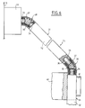
- FIG. 6 partially illustrates a first elongated element in the form of a rod and a corresponding spacer.
- the rod T1 is formed of rigid rectilinear elements 31 and flexible elements 38, suitable for being assembled either one after the other.
- Each element 31 comprises an elongated cylindrical body 32 having at one of its ends a threaded axial blind hole 33 and extended at its opposite end by a threaded axial stud 34.
- Each flexible element 32 comprises a helical spring 35 at one end of which a cylindrical threaded pin 36 is internally screwed by cooperation with the turns of the spring so as to protrude beyond the latter.
- a flexible tubular sheath 37 for example made of heat-shrinkable plastic, is fitted onto the spring 35.
- the external diameter of the sheath 37 is equal to that of the body 32 of the rigid elements 31, and it has a similar surface appearance. to that of this same body.
- Two elements 31 or 38, or an element 31 and an element 38, can be assembled by screwing the stud 34 or the protruding part 36 of one of the elements in the hole 33 or in the turns of the spring 35, at the opposite of the ankle, of the other element.
- the upper end of the rod T1 of FIG. 6 is formed by a flexible element 38 whose pin 36 is screwed into an anchor piece 39 fixed to the wall M, the axis of the pin 36 being oriented perpendicular to the wall and therefore horizontally.
- the anchoring part 39 can be similar to the ceiling anchoring part described in FR-A-2 407 691.
- the flexible end element is followed by one or more rigid elements 31 which extend obliquely downwards, the spring 35 of the terminal element being flexed elastically to take a curved configuration to connect the horizontal direction of the axis of the pin 36 to the oblique direction of the elements 31.
- a second flexible element 38 connects the rigid oblique element or elements to another rigid element 31 oriented vertically and engaging in a vertical end notch of a spacer 40.
- this spacer has a projection 41 externally threaded, s 'extending beyond the rod, and suitable for receiving a cap (not shown internally threaded), for pressing the rod element against the bottom of the notch and immobilizing it with respect to the spacer, as described in FR- A-2 423 186.
- the opposite end of the spacer, not shown, is fixed to the wall M, for example as described above for the spacers E.
- the rigid rod element thus fixed to the spacer can be extended downwards by other rigid elements, the vertical region thus formed receiving hooking parts which can be as described in FR-A-2 423 186 or in FR-A-2 627 241 for example.
- This vertical region can extend to a ground anchoring piece such as that described in FR-A-2 407 691, which includes a tension spring.
- the rod can rest on a lower spacer, then extend obliquely between it and an anchor piece below the wall similar to piece 39, the changes of direction being ensured by flexible elements as at the top part.
- a second rod not shown, formed of one or more rigid elements such as 31, is screwed by an upper terminal stud 36 into a threaded hole in the spacer 40.
- the lower end of the second rod can be anchored to the ground of the same way as that of the first rod, or fixed to the lower spacer by screwing a terminal threaded hole 33 on a threaded stud presented by the spacer, or by cooperation of a dowel such as 36 with this same hole threaded 33 and with the threaded hole of the lower spacer, which is then identical to the upper spacer 40.
- the device according to the invention may comprise first cables or first rods anchored to the ceiling by their upper end and to the wall by their lower end, possibly combined with cables or rods with wall-to-ground anchoring and / or wall-to-wall anchored cables or rods as described in the examples.
- the device can receive indifferently, in combination with the various anchoring modes, shelves, boxes and all other objects, by means of appropriate attachment pieces, in particular, without limitation, as described in FR- A-2 627 241.
Landscapes
- Installation Of Indoor Wiring (AREA)
- Clamps And Clips (AREA)
- Connection Of Plates (AREA)
Claims (11)
- Vorrichtung für die lösbare und verstellbare Befestigung von Objekten, wenigstens ein erstes längliches Element (C11) in Form eines Kabels oder einer Stange umfassend, von dem ein oberes Ende und ein unteres Ende dazu vorgesehen sind, fest verbunden zu werden mit wenigstens einer Trägerwand (M,S) mittels jeweiligen Verankerungsteilen (AM,AS) und lösbaren Befestigungsteilen (QP), von denen jedes in einer verstellbaren Höhe angebracht ist an einem ersten länglichen Element, in einem im wesentlichen vertikal gespannten Zwischenbereich von diesem, um ein Objekte (P1) oder mehrere zu tragen,
dadurch gekennzeichnet,
daß wenigstens ein erstes der genannten Enden vorgesehen ist, in einer Wand (M) verankert zu werden, dadurch daß der genannte Zwischenbereich auf Abstand gehalten wird von der besagten Wand durch wenigstens ein erstes Abstandsstück (E), das sich im wesentlichen horizontal zwischen der Mauer und dem länglichen Element erstreckt, wobei dieses letztere sich auf dem Abstandsstück abstützt durch eine Zone, die den besagten Zwischenbereich begrenzt und einen ersten Endbereich, der sich schräg bis zu dem entsprechenden, an der Mauer befestigten Verankerungsteil (AM) erstreckt, und dadurch, daß dem ersten länglichen Element (C11) oder jedem ersten länglichen Element ein zweites längliches Element (C21) zugeordnet ist, im wesentlichen vertikal gespannt zwischen einem oberen Ende und einem unteren Ende, um Befestigungsteile (QP) aufzunehmen für das oder die zu tragenden Objekte (P1), wobei ein erstes Ende des zweiten länglichen Elements fest verbunden ist mit dem ersten Abstandsstück (E), zwischen der Mauer und der Abstützzone des ersten länglichen Elements auf dieser. - Vorrichtung nach Anspruch 1, dadurch gekennzeichnet, daß das zweite Ende eines ersten länglichen Elements (C11) und gegebenenfalls das des ihm zugeordneten zweiten länglichen Elements (C21) an der Decke oder am Boden (S) verankert sind, wobei das erste längliche Element vertikal gespannt ist zwischen seinem zweiten Ende und seiner Stützzone auf dem Abstandsstück.
- Vorrichtung nach einem der vorhergehenden Ansprüche, dadurch gekennzeichnet, daß die beiden Enden eines ersten länglichen Elements (C12) in der Mauer verankert sind, wobei sich dieses längliche Element außerdem abstützt auf einem zweiten Abstandsstück (E), das sich von der Mauer aus erstreckt, durch eine Zone, die den genannten Zwischenbereich begrenzt und einen zweiten Endbereich, der sich schräg erstreckt bis zu dem an der Mauer (M) befestigten entsprechenden Verankerungsteil (AM).
- Vorrichtung nach Anspruch 3, dadurch gekennzeichnet, daß die beiden Enden eines zweiten länglichen Elements (C22) jeweils fest verbunden sind mit den Abstandsstücken, auf denen sich das zugeordnete erste längliche Element abstützt, zwischen der Mauer (M) und der Abstützzone des ersten länglichen Elements (C12) auf dieser.
- Vorrichtung nach einem der vorhergehenden Ansprüche, dadurch gekennzeichnet, daß jedes erste längliche Element sich im wesentlichen in einer vertikalen Ebene befindet.
- Vorrichtung nach einem der vorhergehenden Ansprüche, dadurch gekennzeichnet, daß jedes erste längliche Element und das zugordnete zweite längliche Element sich im wesentlichen in einer vertikalen Ebene befinden.
- Vorrichtung nach einem der vorhergehenden Ansprüche, dadurch gekennzeichnet, daß die Abstandsstücke Stäbe sind, deren eines Ende an der Wand befestigt wird und deren anderes Ende einem ersten länglichen Element als Stütze dient.
- Vorrichtung nach einem der vorhergehenden Ansprüche, dadurch gekennzeichnet, daß die Abstandsstücke (E) Arretierungseinrichtungen (18,19) der länglichen Elemente in deren Längsrichtung umfassen.
- Vorrichtung nach einem der vorhergehenden Ansprüche, dadurch gekennzeichnet, daß die länglichen Elemente Kabel sind, daß das oder die Teile zur Verankerung in der Mauer Einrichtungen (9) umfassen, die ermöglichen, die Orientierung des Endes des Kabels zu variieren, ohne eine Querkraft auf dieses auszuüben.
- Vorrichtung nach einem der Ansprüche 1 bis 8, dadurch gekennzeichnet, daß die länglichen Elemente Stangen sind, die in ihrem Zwischenbereich und in wenigstens einem Teil ihrer Endbereiche steif und geradlinig sind, wobei diese steifen und geradlinigen Teile (31) untereinander verbunden sind durch biegsame und gekrümmte Teile (38).
- Vorrichtung nach Anspruch 10, dadurch gekennzeichnet, daß die Stangen außerdem biegsame und gekrümmte Teile (38) umfassen, die angrenzen an die Mauerverankerungsstücke (39).
Applications Claiming Priority (2)
| Application Number | Priority Date | Filing Date | Title |
|---|---|---|---|
| FR8915133 | 1989-11-17 | ||
| FR8915133A FR2654599B1 (fr) | 1989-11-17 | 1989-11-17 | Dispositif de fixation a cables ou a tiges. |
Publications (2)
| Publication Number | Publication Date |
|---|---|
| EP0429339A1 EP0429339A1 (de) | 1991-05-29 |
| EP0429339B1 true EP0429339B1 (de) | 1995-05-24 |
Family
ID=9387518
Family Applications (1)
| Application Number | Title | Priority Date | Filing Date |
|---|---|---|---|
| EP90403215A Expired - Lifetime EP0429339B1 (de) | 1989-11-17 | 1990-11-13 | Befestigungsvorrichtung, bestehend aus Kabeln oder Stangen |
Country Status (6)
| Country | Link |
|---|---|
| EP (1) | EP0429339B1 (de) |
| AT (1) | ATE122860T1 (de) |
| CA (1) | CA2030134A1 (de) |
| DE (1) | DE69019681T2 (de) |
| ES (1) | ES2075182T3 (de) |
| FR (1) | FR2654599B1 (de) |
Families Citing this family (4)
| Publication number | Priority date | Publication date | Assignee | Title |
|---|---|---|---|---|
| IT1303511B1 (it) * | 1998-06-26 | 2000-11-06 | Kai Skudelny | Dispositivo di sostegno di scaffali a sbalzo. |
| FR2851442B1 (fr) * | 2003-02-20 | 2005-07-08 | Mobile Cables System | Fixation d'un dispositif d'affichage par un profile rigide pendant par gravite |
| DE20303781U1 (de) | 2003-03-07 | 2003-05-15 | Tecklenborg, Kegel GmbH, 27572 Bremerhaven | Regalsystem zum Abstellen von Gegenständen |
| AT413583B (de) * | 2004-10-08 | 2006-04-15 | Blum Gmbh Julius | Stabilisierungsvorrichtung für möbelteile |
Family Cites Families (4)
| Publication number | Priority date | Publication date | Assignee | Title |
|---|---|---|---|---|
| DE1429494A1 (de) * | 1964-10-05 | 1969-06-19 | Gerhard Brecht Tech Verkaufs G | An Seilen aufgehaengtes Regal |
| US4095768A (en) * | 1976-01-26 | 1978-06-20 | Coats & Clark, Inc. | Bracket assembly |
| FR2420944A1 (fr) * | 1978-03-28 | 1979-10-26 | Hellin J P | Etageres murales suspendues et equilibrees par des cordons loges dans des consoles tubulaires |
| FR2458246A1 (fr) * | 1979-06-13 | 1981-01-02 | Verdeau Jean | Etageres semi-suspendues reglables, prolongeables et amovibles |
-
1989
- 1989-11-17 FR FR8915133A patent/FR2654599B1/fr not_active Expired - Fee Related
-
1990
- 1990-11-13 EP EP90403215A patent/EP0429339B1/de not_active Expired - Lifetime
- 1990-11-13 DE DE69019681T patent/DE69019681T2/de not_active Expired - Lifetime
- 1990-11-13 AT AT90403215T patent/ATE122860T1/de not_active IP Right Cessation
- 1990-11-13 ES ES90403215T patent/ES2075182T3/es not_active Expired - Lifetime
- 1990-11-16 CA CA002030134A patent/CA2030134A1/en not_active Abandoned
Also Published As
| Publication number | Publication date |
|---|---|
| FR2654599A1 (fr) | 1991-05-24 |
| ATE122860T1 (de) | 1995-06-15 |
| CA2030134A1 (en) | 1991-05-18 |
| FR2654599B1 (fr) | 1994-05-20 |
| DE69019681D1 (de) | 1995-06-29 |
| DE69019681T2 (de) | 1996-02-01 |
| EP0429339A1 (de) | 1991-05-29 |
| ES2075182T3 (es) | 1995-10-01 |
Similar Documents
| Publication | Publication Date | Title |
|---|---|---|
| WO1995028889A1 (fr) | Dispositif de stabilisation d'ancrage orthopedique | |
| EP0586320A1 (de) | System zum Befestigen eines Versteifungselementes einer Vorhangfassade an einem Konstruktionselement | |
| CA2276326A1 (fr) | Poteaux et bornes a dispositif de liaison au sol a limite de rupture | |
| FR2537906A1 (fr) | Ratelier a consoles | |
| FR2851442A1 (fr) | Fixation d'un dispositif d'affichage par un profile rigide pendant par gravite | |
| FR2605665A1 (fr) | Organe de support pour element tubulaire | |
| CA2155580C (fr) | Dispositif d'ancrage portatif | |
| EP0429339A1 (de) | Befestigungsvorrichtung, bestehend aus Kabeln oder Stangen | |
| FR2527711A1 (fr) | Noeud d'assemblage pour structures diverses, telles que des echafaudages | |
| EP0235060B1 (de) | Verbindungsriegel für Balken und mit Hilfe dieser Verbindungsriegel hergestelltes Holztragwerk | |
| EP0886021B1 (de) | Stützfussvorrichtung für Stange oder Pfosten | |
| FR2664142A3 (fr) | Etagere destinee a etre fixee a un mur de facon invisible. | |
| CA2021405A1 (fr) | Systeme de fixation a suspension variable et articulation, notamment pour literie ou sieges | |
| FR2656206A3 (en) | Hanger device forming a display | |
| BE679919A (de) | ||
| FR2640860A1 (en) | Support for slat of bedstead and fixing nail | |
| EP1908897B1 (de) | Zaunanlage | |
| FR2458701A1 (fr) | Ferrure d'assemblage d'elements constitutifs de meubles tels que lits et sieges | |
| FR3008119A1 (fr) | Dispositif de liaison de verins sur une structure metallique porteuse, telle qu'une tour d'etaiement, et structure metallique porteuse associee | |
| FR2725480A1 (fr) | Bati a hauteur ou largeur ajustable | |
| FR2544458A1 (fr) | Support, notamment pour la presentation | |
| FR3156153A1 (fr) | Système de clôture | |
| FR2683249A1 (fr) | Piquet pour cloture. | |
| FR3146921A1 (fr) | Equipement de fixation au sol d’un mât de mobilier d’extérieur | |
| FR2648197A1 (fr) | Dispositif de fixation d'elements en bois entre eux pour realiser une structure modulable tel que notamment un abri pour intemperies |
Legal Events
| Date | Code | Title | Description |
|---|---|---|---|
| PUAI | Public reference made under article 153(3) epc to a published international application that has entered the european phase |
Free format text: ORIGINAL CODE: 0009012 |
|
| AK | Designated contracting states |
Kind code of ref document: A1 Designated state(s): AT BE CH DE DK ES FR GB GR IT LI LU NL SE |
|
| 17P | Request for examination filed |
Effective date: 19911128 |
|
| 17Q | First examination report despatched |
Effective date: 19930513 |
|
| GRAA | (expected) grant |
Free format text: ORIGINAL CODE: 0009210 |
|
| AK | Designated contracting states |
Kind code of ref document: B1 Designated state(s): AT BE CH DE DK ES FR GB GR IT LI LU NL SE |
|
| PG25 | Lapsed in a contracting state [announced via postgrant information from national office to epo] |
Ref country code: DK Effective date: 19950524 Ref country code: GR Free format text: LAPSE BECAUSE OF FAILURE TO SUBMIT A TRANSLATION OF THE DESCRIPTION OR TO PAY THE FEE WITHIN THE PRESCRIBED TIME-LIMIT Effective date: 19950524 Ref country code: AT Effective date: 19950524 |
|
| REF | Corresponds to: |
Ref document number: 122860 Country of ref document: AT Date of ref document: 19950615 Kind code of ref document: T |
|
| REF | Corresponds to: |
Ref document number: 69019681 Country of ref document: DE Date of ref document: 19950629 |
|
| GBT | Gb: translation of ep patent filed (gb section 77(6)(a)/1977) |
Effective date: 19950612 |
|
| ITF | It: translation for a ep patent filed | ||
| PG25 | Lapsed in a contracting state [announced via postgrant information from national office to epo] |
Ref country code: SE Effective date: 19950824 |
|
| RAP2 | Party data changed (patent owner data changed or rights of a patent transferred) |
Owner name: GROUPE SMS SA |
|
| REG | Reference to a national code |
Ref country code: CH Ref legal event code: PUE Owner name: GROUPE SMS S.A. |
|
| REG | Reference to a national code |
Ref country code: ES Ref legal event code: FG2A Ref document number: 2075182 Country of ref document: ES Kind code of ref document: T3 |
|
| NLT2 | Nl: modifications (of names), taken from the european patent patent bulletin |
Owner name: GROUPE SMS SA |
|
| PGFP | Annual fee paid to national office [announced via postgrant information from national office to epo] |
Ref country code: LU Payment date: 19951101 Year of fee payment: 6 |
|
| PGFP | Annual fee paid to national office [announced via postgrant information from national office to epo] |
Ref country code: NL Payment date: 19951130 Year of fee payment: 6 |
|
| PGFP | Annual fee paid to national office [announced via postgrant information from national office to epo] |
Ref country code: BE Payment date: 19951201 Year of fee payment: 6 |
|
| RAP4 | Party data changed (patent owner data changed or rights of a patent transferred) |
Owner name: GROUPE SMS SA |
|
| PGFP | Annual fee paid to national office [announced via postgrant information from national office to epo] |
Ref country code: CH Payment date: 19960110 Year of fee payment: 6 |
|
| PLBE | No opposition filed within time limit |
Free format text: ORIGINAL CODE: 0009261 |
|
| STAA | Information on the status of an ep patent application or granted ep patent |
Free format text: STATUS: NO OPPOSITION FILED WITHIN TIME LIMIT |
|
| NLS | Nl: assignments of ep-patents |
Owner name: GROUPE SMS SA;SMS FRANCE |
|
| NLT1 | Nl: modifications of names registered in virtue of documents presented to the patent office pursuant to art. 16 a, paragraph 1 |
Owner name: M.C.S. TECHNOLOGIES |
|
| 26N | No opposition filed | ||
| REG | Reference to a national code |
Ref country code: GB Ref legal event code: 732E |
|
| PG25 | Lapsed in a contracting state [announced via postgrant information from national office to epo] |
Ref country code: LU Free format text: LAPSE BECAUSE OF NON-PAYMENT OF DUE FEES Effective date: 19961113 |
|
| PG25 | Lapsed in a contracting state [announced via postgrant information from national office to epo] |
Ref country code: BE Effective date: 19961130 Ref country code: CH Effective date: 19961130 Ref country code: LI Effective date: 19961130 |
|
| REG | Reference to a national code |
Ref country code: FR Ref legal event code: CJ |
|
| BERE | Be: lapsed |
Owner name: MOBILE CABLES SYSTEM Effective date: 19961130 |
|
| PG25 | Lapsed in a contracting state [announced via postgrant information from national office to epo] |
Ref country code: NL Effective date: 19970601 |
|
| REG | Reference to a national code |
Ref country code: CH Ref legal event code: PL |
|
| NLV4 | Nl: lapsed or anulled due to non-payment of the annual fee |
Effective date: 19970601 |
|
| REG | Reference to a national code |
Ref country code: FR Ref legal event code: CD Ref country code: FR Ref legal event code: CL |
|
| REG | Reference to a national code |
Ref country code: GB Ref legal event code: IF02 |
|
| REG | Reference to a national code |
Ref country code: FR Ref legal event code: JE |
|
| REG | Reference to a national code |
Ref country code: FR Ref legal event code: JE |
|
| REG | Reference to a national code |
Ref country code: FR Ref legal event code: TP Ref country code: FR Ref legal event code: CA |
|
| PGFP | Annual fee paid to national office [announced via postgrant information from national office to epo] |
Ref country code: ES Payment date: 20091204 Year of fee payment: 20 |
|
| PGFP | Annual fee paid to national office [announced via postgrant information from national office to epo] |
Ref country code: IT Payment date: 20091217 Year of fee payment: 20 Ref country code: FR Payment date: 20091216 Year of fee payment: 20 Ref country code: GB Payment date: 20091222 Year of fee payment: 20 |
|
| PGFP | Annual fee paid to national office [announced via postgrant information from national office to epo] |
Ref country code: DE Payment date: 20091223 Year of fee payment: 20 |
|
| REG | Reference to a national code |
Ref country code: GB Ref legal event code: PE20 Expiry date: 20101112 |
|
| REG | Reference to a national code |
Ref country code: ES Ref legal event code: FD2A Effective date: 20110228 |
|
| PG25 | Lapsed in a contracting state [announced via postgrant information from national office to epo] |
Ref country code: GB Free format text: LAPSE BECAUSE OF EXPIRATION OF PROTECTION Effective date: 20101112 |
|
| PG25 | Lapsed in a contracting state [announced via postgrant information from national office to epo] |
Ref country code: ES Free format text: LAPSE BECAUSE OF EXPIRATION OF PROTECTION Effective date: 20101114 |
|
| PG25 | Lapsed in a contracting state [announced via postgrant information from national office to epo] |
Ref country code: DE Free format text: LAPSE BECAUSE OF EXPIRATION OF PROTECTION Effective date: 20101113 |