EP0429352A1 - Siphon d'évacuation pour appareil sanitaire - Google Patents
Siphon d'évacuation pour appareil sanitaire Download PDFInfo
- Publication number
- EP0429352A1 EP0429352A1 EP90403274A EP90403274A EP0429352A1 EP 0429352 A1 EP0429352 A1 EP 0429352A1 EP 90403274 A EP90403274 A EP 90403274A EP 90403274 A EP90403274 A EP 90403274A EP 0429352 A1 EP0429352 A1 EP 0429352A1
- Authority
- EP
- European Patent Office
- Prior art keywords
- drain trap
- drain
- trap according
- sink
- emptying
- Prior art date
- Legal status (The legal status is an assumption and is not a legal conclusion. Google has not performed a legal analysis and makes no representation as to the accuracy of the status listed.)
- Granted
Links
- XLYOFNOQVPJJNP-UHFFFAOYSA-N water Substances O XLYOFNOQVPJJNP-UHFFFAOYSA-N 0.000 claims description 10
- 238000002347 injection Methods 0.000 claims description 3
- 239000007924 injection Substances 0.000 claims description 3
- 230000006978 adaptation Effects 0.000 description 4
- 238000004519 manufacturing process Methods 0.000 description 2
- 238000000034 method Methods 0.000 description 2
- 238000004026 adhesive bonding Methods 0.000 description 1
- 238000007599 discharging Methods 0.000 description 1
- 238000006073 displacement reaction Methods 0.000 description 1
- 238000001746 injection moulding Methods 0.000 description 1
- 238000007689 inspection Methods 0.000 description 1
- 238000002955 isolation Methods 0.000 description 1
- 239000007788 liquid Substances 0.000 description 1
- 238000000465 moulding Methods 0.000 description 1
- 239000002351 wastewater Substances 0.000 description 1
- 238000003466 welding Methods 0.000 description 1
Images

Classifications
-
- E—FIXED CONSTRUCTIONS
- E03—WATER SUPPLY; SEWERAGE
- E03C—DOMESTIC PLUMBING INSTALLATIONS FOR FRESH WATER OR WASTE WATER; SINKS
- E03C1/00—Domestic plumbing installations for fresh water or waste water; Sinks
- E03C1/12—Plumbing installations for waste water; Basins or fountains connected thereto; Sinks
- E03C1/28—Odour seals
- E03C1/284—Odour seals having U-shaped trap
Definitions
- the present invention relates to a siphon for discharging water for a sanitary appliance, the technical design of which gives it very little vertical bulk while respecting the usual flow sections.
- sanitary appliance it is understood to mean any appliance of the sink, washbasin, emptying bin, bathtub, etc. type.
- the traditional drain traps consist of a bent tubing in one or more pieces providing a water guard of about 50 mm to which we must add the diameter of the tubing, which gives the whole a significant height non-compressible with the use of cylindrical tubing.
- the device according to the invention makes it possible to reduce this vertical bulk, while maintaining the water clearance at a value of approximately 50 mm, owing to the fact that the shape of the waste water passage section is modified.
- FIG. 1A we find the sink emptying device (1) provided with its overflow inlet (2) which adapts to the part (3) allowing the evacuation of the dishwasher to be connected. This outlet will be provided with a plug (not shown) in the event that it is not used.
- the rotating part (3) adapts itself to the body (4) of the siphon that the installer connects to the water evacuation pipe (not shown) located laterally or behind the appliance. sanitary reil.
- the part (5) adapts to the siphon body (4) which the installer connects to the water evacuation pipe (not shown).
- the arrows (9) and (10) represent the circuits respectively taken by the liquid during evacuation.
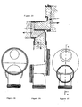
- FIGS. 2A and 2D we find in isolation the part (4) constituting the body of the siphon.
- This part (4) has a structure giving it a reduced height. It is positioned so that its water guard (g) is at the same level as the connection pipes, namely the dishwasher outlet (3) or the connection pieces (5, 6).
- the lower passage section has a very low height (h) and a large width (L).
- the water guard (g) is located directly below at least one sink emptying device (1, 8).
- the part (4) is provided on the one hand at its lower part with a thread for mounting an inspection plug (11) and, on the other hand, at its upper part, with a thread receiving a technical plug (12) having the function of obstructing the orifice necessary for the molding of the body.
- the plug (12) which has no reason to be opened once mounted, can be assembled other than by screwing such as gluing, welding and all other possible assembly techniques.
- the outlets (3, 7) of the dishwasher are positioned at a level higher than that of the water guard (g). These evacuations (3, 7) are optional.
- the part (A) can be rotated and is connected to one or more connecting parts (3, 5, 6) which can be rotated.
- the part (4) is obtained by an injection molding technique using three movable cores whose displacement is shown in Figure 2D by arrows.
- the drain trap can consist of a piece (4) molded in one piece with one or more connecting pieces (3, 5,6) and the emptying device (1, 8).
- This siphon is, according to the embodiment described, adopted for a sink emptying device with one or two tanks provided, if necessary, with a dishwasher drain, but it can also be adapted to a drain device washbasin, tub, bathtub ...
Landscapes
- Engineering & Computer Science (AREA)
- Environmental & Geological Engineering (AREA)
- Health & Medical Sciences (AREA)
- Life Sciences & Earth Sciences (AREA)
- Hydrology & Water Resources (AREA)
- Public Health (AREA)
- Water Supply & Treatment (AREA)
- Sink And Installation For Waste Water (AREA)
Abstract
Description
- La présente invention concerne un siphon d'évacuation d'eau pour appareil sanitaire dont sa conception technique lui confère un très faible encombrement vertical tout en respectant les sections d'écoulement usuelles.
- Par appareil sanitaire, il convient d'entendre tout appareil de type évier, lavabo, bac de vidage, baignoire, etc...
- Les siphons d'évacuation traditionnels sont constitués d'une tubulure coudée en une ou plusieurs pièces ménageant une garde d'eau d'environ 50 mm à laquelle on doit rajouter le diamètre de la tubulure, ce qui confère à l'ensemble une hauteur importante non compressible avec l'utilisation d'une tubulure cylindrique.
- Le dispositif selon l'invention permet de réduire cet encombrement vertical, tout en maintenant la garde d'eau à une valeur d'environ 50 mm, du fait que l'on modifie la forme de la section de passage des eaux usées.
- Les caractéristiques et avantages de l'invention seront mieux compris à la lecture de la description qui va suivre du mode de réalisation de l'invention.
- La figure 1A représente en coupe le siphon selon l'invention en adaptation à un dispositif de vidage d'évier à une cuve muni d'une évacuation de lave-vaisselle.
- La figure 1B représente en coupe le siphon selon l'invention en adaptation à un dispositif de vidage d'évier à deux cuves muni d'une évacuation de lave-vaisselle.
- La figure 2A représente une vue de face de la pièce (4) représentée aux figures 1A et 1B.
- La figure 2B représente une vue de dessus de la pièce (4).
- La figure 2C représente une vue de dessous de la pièce (4).
- La figure 2D représente une coupe selon AA (voir figure 2C) de la pièce (4) avec les directions de déplacement des noyaux du moule permettant une fabrication par injection.
- Sur la figure 1A, nous trouvons le dispositif de vidage d'évier (1) muni de son arrivée de trop-plein (2) qui s'adapte à la pièce (3) permettant de raccorder l'évacuation du lave-vaisselle. Cette évacuation sera munie d'un bouchon (non représenté) dans le cas où elle n'est pas utilisée. La pièce (3) orientable en rotation s'adapte elle-même au corps (4) du siphon que l'installateur relie à la canalisation d'évacuation d'eau (non représentée) située latéralement ou à l'arrière de l'appa reil sanitaire.
- Sur la figure 1B, nous trouvons le dispositif de vidage d'une des cuves de l'évier (1) muni de sona rrivée de trop-plein (2) qui s'adapte à la pièce (5) permettant de raccorder le conduit réglable (6). Ce conduit (6) comporte lui-même une évacuation de lave-vaisselle (7) et un dispositif de raccordement au dispositif de vidage de la deuxième cuve (8).
- La pièce (5) s'adapte au corps (4) de siphon que l'installateur relie à la canalisation d'évacuation d'eau (non représentée). Les flèches (9) et (10) représentent les circuits respectivement empruntés par le liquide pendant l'évacuation.
- Sur les figures 2A et 2D, nous trouvons de manière isolée la pièce (4) constituant le corps du siphon. Cette pièce (4) présente une structure lui conférant une hauteur réduite. Elle est positionnée de manière à ce que sa garde d'eau (g) se situe au même niveau que les tubulures de raccordement, à savoir l'évacuation du lave-vaisselle (3)ou les pièces de raccordement (5, 6). La section de passage inférieure présente une hauteur (h) très faible et une largeur (L) importante. La garde d'eau (g) est située directement au-dessous d'au moins un dispositif de vidage d'évier (1, 8).
- La pièce (4) est munie d'une part au niveau de sa partie inférieure d'un filetage de montage d'un bouchon de visite (11) et, d'autre part, au niveau de sa partie supérieure, d'un filetage recevant un bouchon technique (12) ayant pour fonction d'obstruer l'orifice nécessaire pour le moulage du corps. Le bouchon (12) qui n'a pas de raison d'être ouvert une fois monté, peut être assemblé autrement que par vissage tel que collage, soudure et toutes autres techniques d'assemblage possible.
- Les évacuations (3, 7) du lave-vaisselle sont positionnées à un niveau supérieur à celui de la garde d'eau (g). Ces évacuations (3, 7) sont facultatives.
- La pièce (A) est orientable en rotation et est reliée à une ou plusieurs pièces de raccordement (3, 5, 6) orientables en rotation.
- La pièce (4) est obtenue par une technique de moulage par injection en utilisant trois noyaux mobiles dont le déplacement est représenté sur la figure 2D par des flèches.
- Le siphon d'évacuation peut être constitué d'une pièce (4) moulée d'une seule pièce avec une ou plusieurs pièces à raccordement (3, 5,6) et le dispositif de vidage (1, 8).
- Ce siphon est, selon le mode de réalisation décrit, adopté à un dispositif de vidage d'évier à une ou deux cuves muni, le cas échéant, d'une évacuation de lave-vaisselle mais il peut également être adapté à un dispositif de vidage d'appareil sanitaire du type lavabo, bac, baignoire...
Claims (9)
Applications Claiming Priority (2)
| Application Number | Priority Date | Filing Date | Title |
|---|---|---|---|
| FR8915198 | 1989-11-20 | ||
| FR8915198A FR2654760B1 (fr) | 1989-11-20 | 1989-11-20 | Siphon d'evacuation pour appareil sanitaire. |
Publications (2)
| Publication Number | Publication Date |
|---|---|
| EP0429352A1 true EP0429352A1 (fr) | 1991-05-29 |
| EP0429352B1 EP0429352B1 (fr) | 1995-08-16 |
Family
ID=9387557
Family Applications (1)
| Application Number | Title | Priority Date | Filing Date |
|---|---|---|---|
| EP19900403274 Expired - Lifetime EP0429352B1 (fr) | 1989-11-20 | 1990-11-20 | Siphon d'évacuation pour appareil sanitaire |
Country Status (3)
| Country | Link |
|---|---|
| EP (1) | EP0429352B1 (fr) |
| DE (1) | DE69021691T2 (fr) |
| FR (1) | FR2654760B1 (fr) |
Cited By (2)
| Publication number | Priority date | Publication date | Assignee | Title |
|---|---|---|---|---|
| EP2302142A1 (fr) * | 2009-07-27 | 2011-03-30 | Enrique Rubio Lomillos | Siphon central |
| WO2010140138A3 (fr) * | 2009-06-04 | 2011-10-13 | Garcia Melico Jose Alberto | Système de récupération de chaleur et son thermosiphon |
Citations (5)
| Publication number | Priority date | Publication date | Assignee | Title |
|---|---|---|---|---|
| FR625128A (fr) * | 1926-11-25 | 1927-08-03 | Perfectionnements aux siphons | |
| FR1376802A (fr) * | 1963-10-07 | 1964-10-31 | Procédé de fabrication de siphon d'évier et produit industriel obtenu | |
| GB1163413A (en) * | 1965-09-20 | 1969-09-04 | Ind Products Proprietary Ltd | Improvements in liquid seals or waste traps |
| AT327821B (de) * | 1972-12-21 | 1976-02-25 | Hutterer & Lechner Kg | Siphon aus kunststoff als geruchverschluss fur brausetassen, badewannen u.dgl. |
| GB2156022A (en) * | 1984-03-14 | 1985-10-02 | Key Terrain Ltd | Waste traps with swivellable joints |
-
1989
- 1989-11-20 FR FR8915198A patent/FR2654760B1/fr not_active Expired - Fee Related
-
1990
- 1990-11-20 EP EP19900403274 patent/EP0429352B1/fr not_active Expired - Lifetime
- 1990-11-20 DE DE1990621691 patent/DE69021691T2/de not_active Expired - Fee Related
Patent Citations (5)
| Publication number | Priority date | Publication date | Assignee | Title |
|---|---|---|---|---|
| FR625128A (fr) * | 1926-11-25 | 1927-08-03 | Perfectionnements aux siphons | |
| FR1376802A (fr) * | 1963-10-07 | 1964-10-31 | Procédé de fabrication de siphon d'évier et produit industriel obtenu | |
| GB1163413A (en) * | 1965-09-20 | 1969-09-04 | Ind Products Proprietary Ltd | Improvements in liquid seals or waste traps |
| AT327821B (de) * | 1972-12-21 | 1976-02-25 | Hutterer & Lechner Kg | Siphon aus kunststoff als geruchverschluss fur brausetassen, badewannen u.dgl. |
| GB2156022A (en) * | 1984-03-14 | 1985-10-02 | Key Terrain Ltd | Waste traps with swivellable joints |
Cited By (2)
| Publication number | Priority date | Publication date | Assignee | Title |
|---|---|---|---|---|
| WO2010140138A3 (fr) * | 2009-06-04 | 2011-10-13 | Garcia Melico Jose Alberto | Système de récupération de chaleur et son thermosiphon |
| EP2302142A1 (fr) * | 2009-07-27 | 2011-03-30 | Enrique Rubio Lomillos | Siphon central |
Also Published As
| Publication number | Publication date |
|---|---|
| EP0429352B1 (fr) | 1995-08-16 |
| DE69021691T2 (de) | 1996-05-02 |
| DE69021691D1 (de) | 1995-09-21 |
| FR2654760B1 (fr) | 1993-04-09 |
| FR2654760A1 (fr) | 1991-05-24 |
Similar Documents
| Publication | Publication Date | Title |
|---|---|---|
| EP0496660B1 (fr) | Fosse septique toutes eaux à collecteur de liquide incorporé | |
| US5655230A (en) | Auxiliary urinal retrofit for a commode | |
| JP4729082B2 (ja) | 公共桝用逆流防止装置及び公共桝 | |
| EP0429352B1 (fr) | Siphon d'évacuation pour appareil sanitaire | |
| FR2609482A1 (fr) | Appareil de robinetterie pour le remplissage d'une baignoire | |
| FR2642104A1 (fr) | Dispositif de regulation de debit pour circuit de nettoyage d'un bassin, en particulier d'une piscine | |
| FR2578879A1 (fr) | Robinetterie pour baignoire | |
| JPH0246544Y2 (fr) | ||
| WO1999057384A1 (fr) | Dispositif d'alimentation automatique de l'eau dans un lave-mains de cabinet d'aisance | |
| FR2739115A1 (fr) | Conduit de trop-plein exterieur a un appareil sanitaire | |
| CN206888128U (zh) | 一种简易小便斗 | |
| CA2287065A1 (fr) | Siphon deboucheur | |
| FR2623371A1 (fr) | Vespasienne pour chiens concue pour etre installee dans des lieux publics | |
| KR200292726Y1 (ko) | 세면기의 배수트랩 | |
| FR2678969A1 (fr) | Dispositif de protection d'une tuyauterie d'evacuation d'eaux usees d'une habitation contre la penetration des rats d'egout. | |
| FR2607844A1 (fr) | Urinoir a ouverture oblongue adaptable aux locaux de dimensions reduites | |
| FR2702264A3 (fr) | Dispositif de montage d'une robinetterie mélangeuse de douche. | |
| FR2602807A1 (fr) | Perfectionnement aux dispositifs de reservoir de chasse d'eau pour water-closet | |
| BE530630A (fr) | ||
| FR2800261A1 (fr) | Installation sanitaire et dispositif de vidange pour une telle installation | |
| BE1000562A7 (fr) | Reservoir de chasse avec lave-mains integre. | |
| FR2472708A1 (fr) | Appareil a douches | |
| FR2502211A1 (fr) | Perfectionnements aux dispositifs de vidange pour baignoires | |
| JPH0410315Y2 (fr) | ||
| BE905675A (fr) | Un reservoir de chasse avec lave-mains integre. |
Legal Events
| Date | Code | Title | Description |
|---|---|---|---|
| PUAI | Public reference made under article 153(3) epc to a published international application that has entered the european phase |
Free format text: ORIGINAL CODE: 0009012 |
|
| AK | Designated contracting states |
Kind code of ref document: A1 Designated state(s): DE GB IT |
|
| 17P | Request for examination filed |
Effective date: 19911113 |
|
| 17Q | First examination report despatched |
Effective date: 19911219 |
|
| RAP3 | Party data changed (applicant data changed or rights of an application transferred) |
Owner name: SCPA DUBOSC ET LANDOWSKI |
|
| GRAA | (expected) grant |
Free format text: ORIGINAL CODE: 0009210 |
|
| AK | Designated contracting states |
Kind code of ref document: B1 Designated state(s): DE GB IT |
|
| REF | Corresponds to: |
Ref document number: 69021691 Country of ref document: DE Date of ref document: 19950921 |
|
| ITF | It: translation for a ep patent filed | ||
| GBT | Gb: translation of ep patent filed (gb section 77(6)(a)/1977) |
Effective date: 19951102 |
|
| PLBE | No opposition filed within time limit |
Free format text: ORIGINAL CODE: 0009261 |
|
| STAA | Information on the status of an ep patent application or granted ep patent |
Free format text: STATUS: NO OPPOSITION FILED WITHIN TIME LIMIT |
|
| 26N | No opposition filed | ||
| PGFP | Annual fee paid to national office [announced via postgrant information from national office to epo] |
Ref country code: GB Payment date: 20001115 Year of fee payment: 11 |
|
| PGFP | Annual fee paid to national office [announced via postgrant information from national office to epo] |
Ref country code: DE Payment date: 20010131 Year of fee payment: 11 |
|
| PG25 | Lapsed in a contracting state [announced via postgrant information from national office to epo] |
Ref country code: GB Free format text: LAPSE BECAUSE OF NON-PAYMENT OF DUE FEES Effective date: 20011120 |
|
| REG | Reference to a national code |
Ref country code: GB Ref legal event code: IF02 |
|
| PG25 | Lapsed in a contracting state [announced via postgrant information from national office to epo] |
Ref country code: DE Free format text: LAPSE BECAUSE OF NON-PAYMENT OF DUE FEES Effective date: 20020702 |
|
| GBPC | Gb: european patent ceased through non-payment of renewal fee |
Effective date: 20011120 |
|
| PG25 | Lapsed in a contracting state [announced via postgrant information from national office to epo] |
Ref country code: IT Free format text: LAPSE BECAUSE OF NON-PAYMENT OF DUE FEES;WARNING: LAPSES OF ITALIAN PATENTS WITH EFFECTIVE DATE BEFORE 2007 MAY HAVE OCCURRED AT ANY TIME BEFORE 2007. THE CORRECT EFFECTIVE DATE MAY BE DIFFERENT FROM THE ONE RECORDED. Effective date: 20051120 |