EP0429359B1 - Strahlungsbrenner mit automatischem Stillsetzen im Fall eines Flammenrückschlages - Google Patents
Strahlungsbrenner mit automatischem Stillsetzen im Fall eines Flammenrückschlages Download PDFInfo
- Publication number
- EP0429359B1 EP0429359B1 EP90403283A EP90403283A EP0429359B1 EP 0429359 B1 EP0429359 B1 EP 0429359B1 EP 90403283 A EP90403283 A EP 90403283A EP 90403283 A EP90403283 A EP 90403283A EP 0429359 B1 EP0429359 B1 EP 0429359B1
- Authority
- EP
- European Patent Office
- Prior art keywords
- radiant burner
- orifice
- radiant
- gas
- blocking
- Prior art date
- Legal status (The legal status is an assumption and is not a legal conclusion. Google has not performed a legal analysis and makes no representation as to the accuracy of the status listed.)
- Expired - Lifetime
Links
Images
Classifications
-
- F—MECHANICAL ENGINEERING; LIGHTING; HEATING; WEAPONS; BLASTING
- F23—COMBUSTION APPARATUS; COMBUSTION PROCESSES
- F23D—BURNERS
- F23D14/00—Burners for combustion of a gas, e.g. of a gas stored under pressure as a liquid
- F23D14/46—Details
- F23D14/72—Safety devices, e.g. operative in case of failure of gas supply
- F23D14/82—Preventing flashback or blowback
- F23D14/825—Preventing flashback or blowback using valves
-
- F—MECHANICAL ENGINEERING; LIGHTING; HEATING; WEAPONS; BLASTING
- F16—ENGINEERING ELEMENTS AND UNITS; GENERAL MEASURES FOR PRODUCING AND MAINTAINING EFFECTIVE FUNCTIONING OF MACHINES OR INSTALLATIONS; THERMAL INSULATION IN GENERAL
- F16K—VALVES; TAPS; COCKS; ACTUATING-FLOATS; DEVICES FOR VENTING OR AERATING
- F16K17/00—Safety valves; Equalising valves, e.g. pressure relief valves
- F16K17/36—Safety valves; Equalising valves, e.g. pressure relief valves actuated in consequence of extraneous circumstances, e.g. shock, change of position
- F16K17/38—Safety valves; Equalising valves, e.g. pressure relief valves actuated in consequence of extraneous circumstances, e.g. shock, change of position of excessive temperature
- F16K17/383—Safety valves; Equalising valves, e.g. pressure relief valves actuated in consequence of extraneous circumstances, e.g. shock, change of position of excessive temperature the valve comprising fusible, softening or meltable elements, e.g. used as link, blocking element, seal, closure plug
Definitions
- the present invention relates to a method of arranging a radiant burner for its automatic shutdown in the event of a rear light catch and to an automatic shutter device for implementing this method.
- Radiant burners are used, for example in installations for drying or rectifying the humidity profile of a sheet of paper or textile in continuous movement.
- the outlet of the distribution chamber they include one or more plates of refractory material and good thermal insulator (ceramic, ceramic or metallic fiber ...) whose role is to support combustion on the one hand and transform into radiation infrared the fraction of combustion heat recovered by contact with hot gases on the other hand.
- thermal insulator ceramic, ceramic or metallic fiber
- combustion reentry or tail light catch One of the classic failures of a radiant burner is the phenomenon known as combustion reentry or tail light catch. During such a phenomenon, combustion takes place in the distribution chamber at the rear of the wafer whereas it should normally be carried out on the front face.
- Another cause of ignition is leakage from the back of the radiant burner.
- the mixture will ignite on contact with the hot walls of the burner and in certain cases the combustion will enter through the orifice generating the leak at the rear of the radiant plate.
- the causes of rear leakage can be multiple, for example wear of the seals after aging at the end of the life of the radiant burner, manufacturing defect ...
- thermocouple system for control of the fuel arrival is itself controlled by means of this thermocouple.
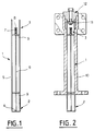
- the elements 5 and 6 consist respectively of a fixed frame 5 and a connecting piece 6 connected to the frame so as to be able to move with guidance thereon.
- This connecting piece 6 supports at its upper end a sealing surface 8 intended to come to bear against the orifice to be closed.
- the connecting piece 6 is resiliently biased by a helical spring 7 in order to bring the sealing surface 8 in the active closed position, when the connecting piece 6 is released from the frame 5 at 4.
- the helical spring 7 is therefore in the inactive compressed position between a part of the frame 5 preferably a spacer 9, and an annular flange of the connecting element 6.
- this annular flange constitutes the sealing surface 8.
- the annular spring retaining flange 7 can be independent of the sealing surface 8, that is to say located for example below the latter, the connecting piece 6 then having with respect to the example shown an extension directed upwards and supporting at its end the sealing surface.
Landscapes
- Engineering & Computer Science (AREA)
- General Engineering & Computer Science (AREA)
- Mechanical Engineering (AREA)
- Chemical & Material Sciences (AREA)
- Combustion & Propulsion (AREA)
- Gas Burners (AREA)
- Control Of Combustion (AREA)
- Regulation And Control Of Combustion (AREA)
Claims (14)
- Strahlungsbrenner mit einem Düsenhalter (12), der einen Düsenkopf (11) trägt, der mit einer Öffnung für die Zufuhr von Brenngas allein oder von Brenngas und einem anderen Gas wie Luft versehen ist, einer durch eine Strahlungsplatte begrenzten Kammer zur Verteilung des Luft/Gas-Gemisches, einem Rohr (10), in welches die Zufuhröffnung mündet und die selbst in die Verteilungskammer mündet, und einer Vorrichtung zur Absperrung der Zufuhröffnung zur Erzeugung eines automatischen Stillstands im Falle eines Flammenrückschlags, wobei die Absperrvorrichtung einen verformbaren Teil (2) zur Temperaturerfassung hat, der über eine Verbindungsstange (6) mit einem Absperrteil (3) der Eintrittsöffnung verbunden ist, der dazu dient, die Öffnung im Falle der Erfassung einer bestimmten Temperatur abzusperren, wobei der Brenner dadurch gekennzeichnet ist, daß die Absperrvorrichtung ein Gestell (5) aufweist, das aus einem umgebogenen Teil mit Verstrebungsschenkeln in Querrichtung besteht, in einer feststehenden Position in das Rohr (10) eingefügt ist, in die Verteilungskammer ragt und den Erfassungsteil (2) trägt, der in der Verteilungskammer und dem Absperrteil (3) angeordnet ist, der in dem Rohr in der Nähe der Zufuhröffnung angeordnet ist.
- Strahlungsbrenner mit einer Düse für Gas oder ein Gas/Luft-Gemisch nach Anspruch 1, dadurch gekennzeichnet, daß die Absperrvorrichtung in dem Brenner von oben her durch Demontage des Düsenhalters (12) eingesetzt wird.
- Strahlungsbrenner nach Anspruch 1, dadurch gekennzeichnet, daß die Absperrvorrichtung in dem Strahlungsabschnitt von unten her durch Demontage der Verteilungskammer eingesetzt wird.
- Strahlungsbrenner nach einem der Ansprüche 1 bis 3, dadurch gekennzeichnet, daß der Erfassungsteil (2) aufgrund eines Elements mit kontrollierter Schmelztemperatur verformbar ist.
- Strahlungsbrenner nach Anspruch 4, dadurch gekennzeichnet, daß das Element mit kontrollierter Schmelztemperatur eine Hartlotstelle oder eine Schweißstelle (4) ist.
- Strahlungsbrenner nach Anspruch 4, dadurch gekennzeichnet, daß das Element mit kontrollierter Schmelztemperatur ein Falzteil ist.
- Strahlungsbrenner nach einem der Ansprüche 1 bis 3, dadurch gekennzeichnet, daß der Erfassungsteil (2) ein Element aus Metall mit Formgedächtnis aufweist.
- Strahlungsbrenner nach einem der Ansprüche 4 bis 7, dadurch gekennzeichnet, daß der Erfassungsteil (2) ein Element aufweist, welches das feststehende Gestell (5) und eine Verbindungsstange (6) verbindet, die eine Absperr-Auflagefläche (8) trägt, so daß die Verformung des Erfassungsteils (2) die Verbindungsstange (6) bezüglich des Gestells (5) bewegt.
- Strahlungsbrenner nach Anspruch 8, dadurch gekennzeichnet, daß die Verbindungsstange (6) elastisch beaufschlagt wird, um die Absperr-Auflagefläche (8) in eine aktive Absperrposition zu bringen, wenn die Verbindungsstange (6) bezüglich des Gestells (5) bewegt wird.
- Strahlungsbrenner nach Anspruch 9, dadurch gekennzeichnet, daß eine Feder (7) zwischen einem Teil des feststehenden Gestells (5) und einem kreisringförmigen Flansch komprimiert ist, der sich auf der Verbindungsstange (6) befindet.
- Strahlungsbrenner nach Anspruch 10, dadurch gekennzeichnet, daß der kreisringförmige Flansch die Absperr-Auflagefläche (8) bildet.
- Strahlungsbrenner nach einem der Ansprüche 1 bis 11, dadurch gekennzeichnet, daß das Gestell (5) ein Metallband ist, das in Form einer Nadel gebogen ist, deren Arme über mindestens eine Querverstrebung (9) verbunden sind, wobei diese oder letztere eine Öffnung aufweist (aufweisen), durch welche die Verbindungsstange (6) geführt wird, die eine Metallstange ist, bei der ein Ende über den Erfassungsteil (2) mit der Basis der Nadel verbunden ist und das andere Ende einen kreisringförmigen Flansch trägt, der eine Absperr-Auflagefläche (8) bildet, wobei eine Feder (7) im inaktiven Zustand zwischen einer Verstrebung (9) und dem kreisringförmigen Flansch komprimiert ist.
- Strahlungsbrenner mit Luft/Gas-Trennung nach einem der Ansprüche 1 bis 12, dadurch gekennzeichnet, daß die Öffnung eine Gaszufuhröffnung ist.
- Strahlungsbrenner mit Luft/Gas-Mischung nach einem der Ansprüche 1 bis 12, dadurch gekennzeichnet, daß die Öffnung eine Luft/Gas-Gemisch-Zufuhröffnung ist.
Applications Claiming Priority (2)
| Application Number | Priority Date | Filing Date | Title |
|---|---|---|---|
| FR8915252 | 1989-11-21 | ||
| FR8915252A FR2654804B1 (fr) | 1989-11-21 | 1989-11-21 | Procede d'arret automatique d'un bruleur radiant en cas de prise de feu arriere et dispositif d'obturation automatique pour la mise en óoeuvre de ce procede. |
Publications (2)
| Publication Number | Publication Date |
|---|---|
| EP0429359A1 EP0429359A1 (de) | 1991-05-29 |
| EP0429359B1 true EP0429359B1 (de) | 1995-09-20 |
Family
ID=9387598
Family Applications (1)
| Application Number | Title | Priority Date | Filing Date |
|---|---|---|---|
| EP90403283A Expired - Lifetime EP0429359B1 (de) | 1989-11-21 | 1990-11-21 | Strahlungsbrenner mit automatischem Stillsetzen im Fall eines Flammenrückschlages |
Country Status (10)
| Country | Link |
|---|---|
| US (1) | US5122054A (de) |
| EP (1) | EP0429359B1 (de) |
| JP (1) | JP2955348B2 (de) |
| AT (1) | ATE128218T1 (de) |
| CA (1) | CA2030337C (de) |
| DE (1) | DE69022541T2 (de) |
| DK (1) | DK0429359T3 (de) |
| ES (1) | ES2081359T3 (de) |
| FR (1) | FR2654804B1 (de) |
| GR (1) | GR3018308T3 (de) |
Cited By (1)
| Publication number | Priority date | Publication date | Assignee | Title |
|---|---|---|---|---|
| DE10237529A1 (de) * | 2002-08-16 | 2004-02-26 | Voith Paper Patent Gmbh | Infrarot-Strahler und mechanische Abschalteinrichtung hierfür |
Families Citing this family (11)
| Publication number | Priority date | Publication date | Assignee | Title |
|---|---|---|---|---|
| GB9617444D0 (en) * | 1996-08-20 | 1996-10-02 | Interotex Eeig | Burner assemblies |
| DE19815785A1 (de) * | 1998-04-08 | 1999-10-14 | Schwank Gmbh | Strahlungsbrenner |
| DE69929769T2 (de) * | 1999-09-09 | 2006-11-02 | Scanferla, Giorgio, Bassano del Grappa | Brennerbaueinheit und Brennerkopf zur Gasmischungsverbrennung |
| US7116900B2 (en) * | 2003-04-01 | 2006-10-03 | Radiant Optics, Inc. | Radiant energy source systems, devices, and methods capturing, controlling, or recycling gas flows |
| CA2521134A1 (en) * | 2003-04-01 | 2004-10-21 | Radiant Optics, Inc. | Radiant energy source systems, devices and methods |
| EP1962003A1 (de) * | 2007-02-26 | 2008-08-27 | GoGaS Goch GmbH & Co. KG | Rückschlagsicherung für einen Strahlungsbrenner |
| US7849821B2 (en) * | 2007-04-12 | 2010-12-14 | Rheem Manufacturing Company | Burner flashback detection and system shutdown apparatus |
| DE102009030163A1 (de) * | 2009-05-12 | 2010-11-18 | Franz Schuck Gmbh | Hauseinführung |
| CN104941952B (zh) * | 2015-05-28 | 2019-02-01 | 沪东中华造船(集团)有限公司 | 一种回火防止器的维修方法 |
| CN112856423B (zh) * | 2021-01-15 | 2022-07-29 | 宁波方太厨具有限公司 | 防干烧灶具 |
| CN118593941A (zh) * | 2024-07-03 | 2024-09-06 | 上海安可科技股份有限公司 | 一种燃气阻火器 |
Family Cites Families (7)
| Publication number | Priority date | Publication date | Assignee | Title |
|---|---|---|---|---|
| US2659426A (en) * | 1950-05-12 | 1953-11-17 | Scully Signal Co | Oil burner with heat responsive fuel cutoff |
| FR1415577A (fr) * | 1964-07-11 | 1965-10-29 | Antargaz | Dispositif de sécurité contre le retour de flamme dans les brûleurs à gaz |
| DE1526013A1 (de) * | 1966-09-24 | 1970-07-16 | Vits Gmbh Maschf | Gasbrenner,insbesondere fuer Infrarotheizung,z.B. fuer Trockner fuer bahnfoermiges Gut |
| DE2453078A1 (de) * | 1974-11-08 | 1976-05-20 | Witt Paul Fa | Sicherheitseinrichtung fuer brenngasleitungen von schneid- oder schweissgeraeten |
| DE2510972B2 (de) * | 1975-03-13 | 1980-06-26 | Hartmann & Braun Ag, 6000 Frankfurt | In eine Gasleitung einzuschaltende, flammensperrende Vorrichtung |
| FR2467165B1 (fr) * | 1979-10-11 | 1986-05-09 | Tempo Sanys | Dispositif de decoupage de rondelles ou autre forme de materiau en forme de fibre, par exemple de coton, ainsi que de decoupage et d'obturation de sachets remplis de ces rondelles par un opercule de meme forme |
| JPS5855607A (ja) * | 1981-09-28 | 1983-04-02 | Sharp Corp | ガス燃焼装置 |
-
1989
- 1989-11-21 FR FR8915252A patent/FR2654804B1/fr not_active Expired - Lifetime
-
1990
- 1990-11-20 CA CA002030337A patent/CA2030337C/fr not_active Expired - Lifetime
- 1990-11-21 DK DK90403283.6T patent/DK0429359T3/da active
- 1990-11-21 EP EP90403283A patent/EP0429359B1/de not_active Expired - Lifetime
- 1990-11-21 DE DE69022541T patent/DE69022541T2/de not_active Expired - Lifetime
- 1990-11-21 US US07/616,439 patent/US5122054A/en not_active Expired - Lifetime
- 1990-11-21 AT AT90403283T patent/ATE128218T1/de not_active IP Right Cessation
- 1990-11-21 ES ES90403283T patent/ES2081359T3/es not_active Expired - Lifetime
- 1990-11-21 JP JP2317617A patent/JP2955348B2/ja not_active Expired - Lifetime
-
1995
- 1995-12-05 GR GR950403427T patent/GR3018308T3/el unknown
Cited By (1)
| Publication number | Priority date | Publication date | Assignee | Title |
|---|---|---|---|---|
| DE10237529A1 (de) * | 2002-08-16 | 2004-02-26 | Voith Paper Patent Gmbh | Infrarot-Strahler und mechanische Abschalteinrichtung hierfür |
Also Published As
| Publication number | Publication date |
|---|---|
| JP2955348B2 (ja) | 1999-10-04 |
| FR2654804B1 (fr) | 1994-06-03 |
| CA2030337C (fr) | 1999-09-21 |
| JPH03211309A (ja) | 1991-09-17 |
| ATE128218T1 (de) | 1995-10-15 |
| DK0429359T3 (da) | 1996-01-15 |
| FR2654804A1 (fr) | 1991-05-24 |
| ES2081359T3 (es) | 1996-03-01 |
| DE69022541T2 (de) | 1996-03-21 |
| US5122054A (en) | 1992-06-16 |
| GR3018308T3 (en) | 1996-03-31 |
| EP0429359A1 (de) | 1991-05-29 |
| CA2030337A1 (fr) | 1991-05-22 |
| DE69022541D1 (de) | 1995-10-26 |
Similar Documents
| Publication | Publication Date | Title |
|---|---|---|
| EP0429359B1 (de) | Strahlungsbrenner mit automatischem Stillsetzen im Fall eines Flammenrückschlages | |
| FR2698676A1 (fr) | Vanne thermosensible. | |
| FR2595134A1 (fr) | Bruleur a gaz a soufflage d'air force pour un poele a bois | |
| MC1125A1 (fr) | Installation pour la combustion de combustibles nobles | |
| EP0921350A1 (de) | Sauerstoff-Brennstoffbrenner | |
| EP0269487B2 (de) | Vormischgasbrenner mit Druckluftführung | |
| EP0059137A1 (de) | Zündvorrichtung für Brennstoff, der in einem schnellströmenden Gasstrom eingespritzt wird | |
| FR2646892A1 (fr) | Bruleur pilote pour dispositif de securite d'appareil a combustion de gaz | |
| FR2807145A1 (fr) | Dispositif d'agencement d'un thermocouple classique par l'interieur du conduit d'alimentation air-gaz d'un bruleur a gaz pour assurer les fonctions de "securite froide" et "securite chaude" | |
| EP0128809B1 (de) | Gasbrenner des Vormischtyps und mit Flammenüberwachung und Anwendung dieses Brenners insbesondere für Tauchrohranlage | |
| FR2576395A1 (fr) | Dispositif pour la combustion de combustibles solides | |
| CA2152397A1 (fr) | Buse de chalumeau a gaz | |
| EP0660039B1 (de) | Brennerkopf für Gasbrenner, Brenner versehen mit einem solchen Kopf und Verbrennungsverfahren | |
| EP0269488B1 (de) | Vormischgasbrenner mit Flammenüberwachung | |
| JPS5939647B2 (ja) | 燃焼安全装置 | |
| FR2807144A1 (fr) | Dispositif d'agencement d'un thermocouple classique par l'interieur du conduit air-gaz d'un bruleur a gaz pour assurer les fonctions de "securite froide" et de "securite chaude" | |
| US20260033670A1 (en) | Heating and cooking apparatus | |
| FR2624260A1 (fr) | Appareil de chauffage a gaz | |
| FR2678356A1 (fr) | Bruleur catalytique a air induit. | |
| BE1006302A3 (fr) | Buse, notamment a allumage piezo-electrique, et module d'allumage comportant une telle buse. | |
| FR2622669A1 (fr) | Soupape de decharge pour canalisation de transport de fluide chaud | |
| FR2751735A1 (fr) | Chaudiere de chauffage central a bruleur fioul | |
| FR2708337A1 (fr) | Appareil de chauffage avec brûleur catalytique, et un dispositif de visualisation de son allumage. | |
| EP0111609A1 (de) | Entzündungs- und Speisevorrichtung für Gasradiatoren | |
| FR2791417A1 (fr) | Bruleur a detecteur de flamme |
Legal Events
| Date | Code | Title | Description |
|---|---|---|---|
| PUAI | Public reference made under article 153(3) epc to a published international application that has entered the european phase |
Free format text: ORIGINAL CODE: 0009012 |
|
| AK | Designated contracting states |
Kind code of ref document: A1 Designated state(s): AT BE CH DE DK ES GB GR IT LI LU NL SE |
|
| 17P | Request for examination filed |
Effective date: 19910528 |
|
| 17Q | First examination report despatched |
Effective date: 19920603 |
|
| GRAA | (expected) grant |
Free format text: ORIGINAL CODE: 0009210 |
|
| AK | Designated contracting states |
Kind code of ref document: B1 Designated state(s): AT BE CH DE DK ES GB GR IT LI LU NL SE |
|
| REF | Corresponds to: |
Ref document number: 128218 Country of ref document: AT Date of ref document: 19951015 Kind code of ref document: T |
|
| REF | Corresponds to: |
Ref document number: 69022541 Country of ref document: DE Date of ref document: 19951026 |
|
| ITF | It: translation for a ep patent filed | ||
| GBT | Gb: translation of ep patent filed (gb section 77(6)(a)/1977) |
Effective date: 19951014 |
|
| REG | Reference to a national code |
Ref country code: DK Ref legal event code: T3 |
|
| REG | Reference to a national code |
Ref country code: GR Ref legal event code: FG4A Free format text: 3018308 |
|
| REG | Reference to a national code |
Ref country code: ES Ref legal event code: FG2A Ref document number: 2081359 Country of ref document: ES Kind code of ref document: T3 |
|
| PLBE | No opposition filed within time limit |
Free format text: ORIGINAL CODE: 0009261 |
|
| STAA | Information on the status of an ep patent application or granted ep patent |
Free format text: STATUS: NO OPPOSITION FILED WITHIN TIME LIMIT |
|
| 26N | No opposition filed | ||
| PGFP | Annual fee paid to national office [announced via postgrant information from national office to epo] |
Ref country code: DK Payment date: 20001113 Year of fee payment: 11 |
|
| PGFP | Annual fee paid to national office [announced via postgrant information from national office to epo] |
Ref country code: LU Payment date: 20001124 Year of fee payment: 11 |
|
| PGFP | Annual fee paid to national office [announced via postgrant information from national office to epo] |
Ref country code: GR Payment date: 20001129 Year of fee payment: 11 |
|
| PGFP | Annual fee paid to national office [announced via postgrant information from national office to epo] |
Ref country code: CH Payment date: 20011025 Year of fee payment: 12 |
|
| PGFP | Annual fee paid to national office [announced via postgrant information from national office to epo] |
Ref country code: SE Payment date: 20011106 Year of fee payment: 12 |
|
| PG25 | Lapsed in a contracting state [announced via postgrant information from national office to epo] |
Ref country code: LU Free format text: LAPSE BECAUSE OF NON-PAYMENT OF DUE FEES Effective date: 20011121 Ref country code: DK Free format text: LAPSE BECAUSE OF NON-PAYMENT OF DUE FEES Effective date: 20011121 |
|
| PG25 | Lapsed in a contracting state [announced via postgrant information from national office to epo] |
Ref country code: GR Free format text: LAPSE BECAUSE OF NON-PAYMENT OF DUE FEES Effective date: 20011130 |
|
| REG | Reference to a national code |
Ref country code: GB Ref legal event code: IF02 |
|
| REG | Reference to a national code |
Ref country code: DK Ref legal event code: EBP |
|
| PG25 | Lapsed in a contracting state [announced via postgrant information from national office to epo] |
Ref country code: SE Free format text: LAPSE BECAUSE OF NON-PAYMENT OF DUE FEES Effective date: 20021122 |
|
| PG25 | Lapsed in a contracting state [announced via postgrant information from national office to epo] |
Ref country code: LI Free format text: LAPSE BECAUSE OF NON-PAYMENT OF DUE FEES Effective date: 20021130 Ref country code: CH Free format text: LAPSE BECAUSE OF NON-PAYMENT OF DUE FEES Effective date: 20021130 |
|
| EUG | Se: european patent has lapsed | ||
| REG | Reference to a national code |
Ref country code: CH Ref legal event code: PL |
|
| PGFP | Annual fee paid to national office [announced via postgrant information from national office to epo] |
Ref country code: ES Payment date: 20091126 Year of fee payment: 20 Ref country code: AT Payment date: 20091103 Year of fee payment: 20 Ref country code: DE Payment date: 20091127 Year of fee payment: 20 |
|
| PGFP | Annual fee paid to national office [announced via postgrant information from national office to epo] |
Ref country code: NL Payment date: 20091123 Year of fee payment: 20 |
|
| PGFP | Annual fee paid to national office [announced via postgrant information from national office to epo] |
Ref country code: GB Payment date: 20091125 Year of fee payment: 20 Ref country code: IT Payment date: 20091128 Year of fee payment: 20 |
|
| PGFP | Annual fee paid to national office [announced via postgrant information from national office to epo] |
Ref country code: BE Payment date: 20091224 Year of fee payment: 20 |
|
| BE20 | Be: patent expired |
Owner name: *SOLARONICS VANEECKE Effective date: 20101121 |
|
| REG | Reference to a national code |
Ref country code: NL Ref legal event code: V4 Effective date: 20101121 |
|
| REG | Reference to a national code |
Ref country code: GB Ref legal event code: PE20 Expiry date: 20101120 |
|
| PG25 | Lapsed in a contracting state [announced via postgrant information from national office to epo] |
Ref country code: NL Free format text: LAPSE BECAUSE OF EXPIRATION OF PROTECTION Effective date: 20101121 |
|
| PG25 | Lapsed in a contracting state [announced via postgrant information from national office to epo] |
Ref country code: GB Free format text: LAPSE BECAUSE OF EXPIRATION OF PROTECTION Effective date: 20101120 |
|
| PG25 | Lapsed in a contracting state [announced via postgrant information from national office to epo] |
Ref country code: DE Free format text: LAPSE BECAUSE OF EXPIRATION OF PROTECTION Effective date: 20101121 |
|
| REG | Reference to a national code |
Ref country code: ES Ref legal event code: FD2A Effective date: 20130730 |
|
| PG25 | Lapsed in a contracting state [announced via postgrant information from national office to epo] |
Ref country code: ES Free format text: LAPSE BECAUSE OF EXPIRATION OF PROTECTION Effective date: 20101122 |