EP0429381B1 - Machine agricole avec dispositif de suspension du groupe d'organes de travail perfectionné - Google Patents
Machine agricole avec dispositif de suspension du groupe d'organes de travail perfectionné Download PDFInfo
- Publication number
- EP0429381B1 EP0429381B1 EP90440106A EP90440106A EP0429381B1 EP 0429381 B1 EP0429381 B1 EP 0429381B1 EP 90440106 A EP90440106 A EP 90440106A EP 90440106 A EP90440106 A EP 90440106A EP 0429381 B1 EP0429381 B1 EP 0429381B1
- Authority
- EP
- European Patent Office
- Prior art keywords
- articulation
- agricultural machine
- accordance
- suspension
- elements
- Prior art date
- Legal status (The legal status is an assumption and is not a legal conclusion. Google has not performed a legal analysis and makes no representation as to the accuracy of the status listed.)
- Expired - Lifetime
Links
- 239000000725 suspension Substances 0.000 title claims abstract description 427
- 238000006073 displacement reaction Methods 0.000 claims 4
- 235000012054 meals Nutrition 0.000 claims 1
- 238000003306 harvesting Methods 0.000 description 75
- 210000000056 organ Anatomy 0.000 description 19
- 230000008878 coupling Effects 0.000 description 6
- 238000010168 coupling process Methods 0.000 description 6
- 238000005859 coupling reaction Methods 0.000 description 6
- 230000005540 biological transmission Effects 0.000 description 5
- 230000000694 effects Effects 0.000 description 3
- 238000010276 construction Methods 0.000 description 2
- 210000002414 leg Anatomy 0.000 description 2
- 210000004417 patella Anatomy 0.000 description 2
- 208000031968 Cadaver Diseases 0.000 description 1
- 150000001768 cations Chemical class 0.000 description 1
- 229910003460 diamond Inorganic materials 0.000 description 1
- 239000010432 diamond Substances 0.000 description 1
- 239000012530 fluid Substances 0.000 description 1
- 150000002500 ions Chemical class 0.000 description 1
- 238000012423 maintenance Methods 0.000 description 1
- 238000004519 manufacturing process Methods 0.000 description 1
- 238000012986 modification Methods 0.000 description 1
- 230000004048 modification Effects 0.000 description 1
- 238000004806 packaging method and process Methods 0.000 description 1
- 230000036316 preload Effects 0.000 description 1
- 238000006467 substitution reaction Methods 0.000 description 1
Images



Classifications
-
- A—HUMAN NECESSITIES
- A01—AGRICULTURE; FORESTRY; ANIMAL HUSBANDRY; HUNTING; TRAPPING; FISHING
- A01D—HARVESTING; MOWING
- A01D67/00—Undercarriages or frames specially adapted for harvesters or mowers; Mechanisms for adjusting the frame; Platforms
-
- A—HUMAN NECESSITIES
- A01—AGRICULTURE; FORESTRY; ANIMAL HUSBANDRY; HUNTING; TRAPPING; FISHING
- A01D—HARVESTING; MOWING
- A01D34/00—Mowers; Mowing apparatus of harvesters
- A01D34/01—Mowers; Mowing apparatus of harvesters characterised by features relating to the type of cutting apparatus
- A01D34/412—Mowers; Mowing apparatus of harvesters characterised by features relating to the type of cutting apparatus having rotating cutters
- A01D34/63—Mowers; Mowing apparatus of harvesters characterised by features relating to the type of cutting apparatus having rotating cutters having cutters rotating about a vertical axis
- A01D34/64—Mowers; Mowing apparatus of harvesters characterised by features relating to the type of cutting apparatus having rotating cutters having cutters rotating about a vertical axis mounted on a vehicle, e.g. a tractor, or drawn by an animal or a vehicle
- A01D34/66—Mowers; Mowing apparatus of harvesters characterised by features relating to the type of cutting apparatus having rotating cutters having cutters rotating about a vertical axis mounted on a vehicle, e.g. a tractor, or drawn by an animal or a vehicle with two or more cutters
- A01D34/661—Mounting means
-
- Y—GENERAL TAGGING OF NEW TECHNOLOGICAL DEVELOPMENTS; GENERAL TAGGING OF CROSS-SECTIONAL TECHNOLOGIES SPANNING OVER SEVERAL SECTIONS OF THE IPC; TECHNICAL SUBJECTS COVERED BY FORMER USPC CROSS-REFERENCE ART COLLECTIONS [XRACs] AND DIGESTS
- Y10—TECHNICAL SUBJECTS COVERED BY FORMER USPC
- Y10S—TECHNICAL SUBJECTS COVERED BY FORMER USPC CROSS-REFERENCE ART COLLECTIONS [XRACs] AND DIGESTS
- Y10S56/00—Harvesters
- Y10S56/10—Uneven terrain compensation
-
- Y—GENERAL TAGGING OF NEW TECHNOLOGICAL DEVELOPMENTS; GENERAL TAGGING OF CROSS-SECTIONAL TECHNOLOGIES SPANNING OVER SEVERAL SECTIONS OF THE IPC; TECHNICAL SUBJECTS COVERED BY FORMER USPC CROSS-REFERENCE ART COLLECTIONS [XRACs] AND DIGESTS
- Y10—TECHNICAL SUBJECTS COVERED BY FORMER USPC
- Y10S—TECHNICAL SUBJECTS COVERED BY FORMER USPC CROSS-REFERENCE ART COLLECTIONS [XRACs] AND DIGESTS
- Y10S56/00—Harvesters
- Y10S56/14—Hitch
Definitions
- Such an agricultural machine is known, produced in the form of a mower (DE-U-87 01093 and prospectus KRONE "front mower with AFL discs" ref. NIE 7-1.88).
- This known mower is intended to be coupled to the front hitch of a tractor. It includes a chassis and a mowing group linked to it by a deformable parallelogram suspension device.
- This chassis comprises a central console which is provided, at the rear, with a coupling triangle allowing the mower to be coupled to the front coupling of the tractor and which extends above the mowing group.
- the latter is linked to the front of the console by means of said deformable parallelogram suspension device, which comprises three suspension connecting rods: a rigid central suspension connecting rod and two equally rigid lateral suspension connecting rods.
- the central suspension rod extends higher than the two lateral suspension rods.
- the latter extend, in turn, a relatively large distance from each other.
- the central suspension rod is connected to the console by means of a first ball joint and to the mowing unit by means of a second ball joint.
- the two lateral suspension rods are also each linked to the console by means of a ball joint. They are, on the other hand, each linked to the mowing group by means of a cylindrical articulation. Moreover, they extend, in top view, at least substantially parallel in the direction of advance to work. In side view and during work, the suspension rods extend rearwards and downwards from their respective articulation to the console to their respective articulation to the mowing unit.
- the mowing unit of this machine known can go up and down freely.
- the pivoting of the mowing group around a straight line directed towards the front can only be achieved, however, because the cylindrical articulations of the two lateral suspension rods are provided with sufficient clearance (which should be greater than the clearance of usual operation of a cylindrical joint). In any case, this pivoting remains relatively limited and the life of the cylindrical joints of the two lateral suspension rods can prove to be problematic during intensive use.
- the front joints of the three suspension rods are certainly provided on a central console.
- the front joints of the two lateral suspension rods are relatively distant from each other. This is necessary in order to be able to obtain a sufficient connection between said lateral suspension rods and the mowing unit, capable of absorbing the forces appearing when the mower is used.
- EP-A-0 297 012 there is known a trailed mower comprising a frame which extends transversely to the direction of advance to work. At each of its ends, this chassis is provided with a wheel by means of which it rests on the ground. In the middle part, the chassis is linked to a drawbar which makes it possible to attach the mower to a tractor and which is linked to the chassis by an articulation with a vertical axis.
- the chassis supports a group of working elements by means of a deformable parallelogram suspension device. This suspension device comprises two pairs of suspension rods each extending near one end of the chassis.
- the group of working members of this known mower can also move up and down freely.
- the pivoting of the group of working members around a straight line directed towards the front can only be achieved, however, because the two pairs of suspension rods are relatively distant from each other. In all cases, this pivoting also remains relatively limited and the articulations of the suspension rods risk being subjected to significant forces during said pivoting.
- a trailed mower conditioner is also known.
- This comprises a chassis and a group of articulated working members linked thereto via an intermediate structure and a suspension device with a deformable parallelogram.
- the chassis has a diamond shape, the large axis of which is directed transversely to the working direction, while the small axis is directed according to the direction of work.
- Each side of the rhombus is made up of a beam. These beams are fixed at their respective inner end to a central beam materializing the minor axis of the rhombus. At their outer end, the beams are fixed two by two to a respective amount.
- the chassis rests on two wheels, each of which is linked to an upright by means of a wheel arm.
- the suspension device of this known machine comprises a rigid central suspension rod and two equally rigid lateral suspension rods.
- the central suspension rod is linked to the chassis by a cylindrical articulation and to the intermediate structure by a swiveling articulation.
- the two lateral connecting rods are linked both to the chassis and to the intermediate structure by swiveling joints.
- This deformable parallelogram suspension device combined with the intermediate structure and with the articulation of the group of working members, allows the group of working members to adapt to the terrain.
- the two lateral suspension rods are relatively distant from each other. This guarantees a good connection of these lateral suspension rods to the intermediate structure (to which the group of working members is linked) capable of absorbing the forces appearing during the use of the mower.
- this requires a large frame on which the lateral suspension rods can to be hooked.
- Such a chassis increases the weight of the machine, as well as its production costs.
- the objective of the present invention therefore consists in creating an agricultural machine comprising a suspension device which does not have the drawbacks of known devices, and in which it is possible to group the points of connection of the suspension device to the chassis, while obtaining a good connection of the suspension device to the group of working members capable of absorbing the forces appearing in particular during the use of the agricultural machine.
- a first agricultural machine is characterized in that said suspension means additionally comprise a second central suspension member forming with the first central suspension member a second quadrilateral deformable in an direction at least substantially vertical equivalent to the first quadrilateral, and the axis of the first articulation and the axis of the second articulation extending at least substantially in the second plane, said second articulation extending additionally at least substantially at the level of the first straight and its axis having in addition at least substantially a common point with the first straight and with the second straight, and that the first articulation of a lateral suspension member extends at least substantially in the foreground, its axis being located at least substantially on the axis of the first articulation of the second central suspension member (claim independent ion 1).
- a second agricultural machine is characterized in that the first articulations of the lateral suspension members extend at least substantially in the foreground, their axes being at least substantially coincident (independent claim 2).
- suspension devices of agricultural machines of the invention no longer have the drawback of the suspension devices of known agricultural machines.
- the lateral suspension member (s) are in particular provided to avoid pivoting of the group of working members around a straight line passing through the axis of the second articulation of the central suspension member having two articulations of the ball joint type, and by the point of intersection of the first and second straight lines.
- the suspension device for agricultural machines also has the advantage of being able to group the first articulations of the central suspension members and of the lateral suspension members in the same zone of the structure provided with the coupling means. This results in a simplification of the construction thereof.
- This makes it possible, for example, to very easily provide this structure with a unit to which the coupling means is linked by means of which the agricultural machine is coupled to a motor vehicle, and which supports, if necessary, a part at least transmission means transmitting the movement received from a motor source to the group of working members.
- This unit can be used for a whole range of agricultural machines with different working widths. For this, it will suffice to link to it the group or groups of suitable working members by means of the suspension device (s), the first respective joints of which are grouped in the same zone.
- the second articulations of the lateral suspension members are distant from the foreground, a very good connection is obtained between the suspension device and the group of working members. Furthermore, these lateral suspension members create a stiffening of the group of working members, which is a function of the distance separating their second articulations from the foreground. This is particularly of great interest in machines with a large working width, in which the group of working members has a relatively large dimension.
- the group of working members has a vertical median plane, it may, in accordance with an additional characteristic of the invention, be provided for the foreground is at least substantially coincident with said median plane.
- the foreground may advantageously extend at least substantially in the direction of advance to work.
- the first and second deformable quadrilateral may be pulled at work, that is to say that the first joints of a central suspension member as well as of a lateral suspension member extend, taking into account the direction of advance to work, more forward than their second joints.
- the first and the second deformable quadrilateral will even be each produced in the form of a deformable parallelogram.
- the second articulation of a lateral suspension member could, of course, be of the cylindrical type. However, for simplification of the practical embodiment, it will be desirable for it to also be of the ball joint type.
- At least one lateral suspension member can be provided on each side of the first straight line.
- the second joints of said organs side suspension nes extend at least substantially symmetrically with respect to the first straight line.
- adjustment members intended for adjusting the distance separating its first articulation from its second articulation.
- the second central suspension member extends higher and, preferably, above the first central suspension member.
- the lateral suspension members extend higher and, preferably, above the central suspension member.
- the agricultural machine of the invention comprises, in addition, means limiting or preventing the movement of the group of organs of work transverse to the direction of advance to work.
- this first cylindrical articulation could even be of the pivot type.
- This articulation of the cylindrical or pivot type can be achieved by at least one cylindrical bearing or by two ball joints spaced from one another and whose centers define the axis of said articulation.
- first articulation of the second central suspension member may be of the ball joint type and for the means limiting or preventing the movement of the group of working members transverse to the direction of advance to work, limit or condemn the pivoting of the group of working members around a straight line passing through the centers of the first articulations of the central suspension members.
- said means may be constituted by two stops integral with the structure of the agricultural machine.
- said means may be constituted by a member which extends between two guide surfaces at least substantially planar and at least substantially parallel to the foreground. If the second articulation of the second central suspension member is of the ball joint type, the latter does not necessarily rotate around the first straight line which constitutes its longitudinal axis, when the group of working members rotates around said first straight line.
- the member extending between the two guide surfaces may have the appropriate shape allowing its translation, practically without play, between said guide surfaces.
- the second articulation of the second central suspension member may be of the cylindrical type.
- said second central suspension member rotates around the first straight line which constitutes its longitudinal axis, when the group of working members rotates around this first straight line.
- the member extending between the two guide surfaces may include a part cylindrical whose longitudinal axis is at least substantially coincident with the first straight line. In this way, said cylindrical part can be translated, practically without play, between the two guide surfaces and rotate around its longitudinal axis.
- a lateral suspension member may be either rigid, or essentially of the type or only capable of working in traction.
- said lateral suspension member may, for example, consist of a cable.
- said means may consist of a cylindrical finger, the longitudinal axis of which is at least substantially coincident with the first straight line, and two guide surfaces at least substantially planar and at least substantially parallel to the foreground, between which s 'extends the cylindrical finger.
- said cylindrical finger can be translated, practically without play, between the two guide surfaces and rotate around its longitudinal axis.
- said cylindrical finger is integral with at least one of the lateral suspension members.
- the agricultural machine of the invention comprises several lateral suspension members rigidly connected to one another.
- the structure of the agricultural machine may include a simple console at the front end of which are linked the central suspension member (s), as well as the or the lateral suspension members.
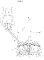
- FIG. 1 shows an agricultural machine according to the invention, produced in the form of a mower (1). This is coupled to an agricultural tractor (2).
- the drawbar (4) consists of a body (3) and a drawbar (4).
- the drawbar (4) for its part, consists of a primary drawbar (5) intended to be coupled to the lower arms (6) of the coupling of the agricultural tractor (2) and a secondary drawbar (7) linked to the body. (3) of the mower (1).
- the primary drawbar (5) is linked to the front end of the secondary drawbar (7) by means of a connecting device (8) known to those skilled in the art and which allows in particular a pivoting of the primary drawbar (5 ) relative to the secondary drawbar (7) about an axis at least substantially vertical.
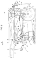
- the secondary drawbar (7) is connected to the body (3) by means of an articulation (9) of geometric axis (10) ( Figure 2) at least substantially vertical and extending at least substantially in the vertical median plane (11) of the body (3), directed in the direction of advance (12) at work.
- the angular position of the drawbar (4) relative to the body (3) can be changed by rotating the drawbar (4) around the axis (10) of the joint (9).
- Putting in the desired angular position and the maintenance in it are achieved by a hydraulic cylinder (13). Thanks to this arrangement, the body (3) of the mower (1) can, in particular at work, extend - seen from the rear in the direction of advance (12) at work - either to the right or to the left of the agricultural tractor (2). This allows mowing back and forth.
- the body (3) of the mower (1) comprises a frame (14) which rests on the ground - especially at work - by means of two wheels (15) which each extend near a respective outer end of said chassis (14).
- Each wheel (15) is linked to the chassis (14) by means of a wheel arm (16) itself linked to said chassis (14) by means of a pivot type hinge (17) with a geometric axis at least substantially horizontal and directed at least substantially perpendicular to the direction of advance (12) at work.
- the geometric axes of the articulations (17) of the two wheels (15) are at least substantially coincident.
- each wheel arm (16) and the chassis (14) is also provided a hydraulic cylinder (18) which allows the wheel arm (16) and the corresponding wheel (15) to pivot relative to the chassis (14) around the geometric axis of the corresponding joint (17). This allows the chassis (14) to be approached from the ground (109) during the mowing phase and to be moved away from the ground (109) when the mowing is interrupted.
- the body (3) of the mower (1) further comprises a group of working members which is here constituted by a harvesting mechanism (19) provided with cutting members (20) and processing members (21) of the product cut by the cutting members (20), such as packaging members for example.
- This harvesting mechanism (19) is linked to the chassis (14) by means of a suspension device (22) which will be described later in more detail.
- the harvesting mechanism (19) is driven from the PTO (23) of the tractor (2) which attacks, by means of a telescopic shaft with universal joints (24), the input shaft (not shown) of the connecting device (8) which is also, in a manner known to those skilled in the art, a movement transmission device.
- the output shaft (25) of the link and transmission device (8) transmits the movement to a transmission shaft (26) which is housed inside the secondary drawbar (7).
- the transmission shaft (26) is coupled to the input shaft (27) of an intermediate casing (28) which extends at the connection of the secondary drawbar (7) to the chassis (14).
- This intermediate casing (28) ( Figure 2) consists of two parts: an upper part (29) secured to the secondary drawbar (7) and a lower part (30) secured to the frame (14).
- the upper part (29) supports on the one hand the input shaft (27) and on the other hand an intermediate output shaft (31). These two shafts (27, 31) are coupled by means of a pair of bevel gears (32) housed in the upper part (29).
- the lower part (30) supports on the one hand an intermediate input shaft (33) and on the other hand an output shaft (34).
- the two shafts (33, 34) are linked in rotation by means of a pair of bevel gear wheels (35) housed in the lower part (30).
- the intermediate output shaft (31) and the intermediate input shaft (33) are coupled to each other by means of a universal joint (36).
- these two intermediate shafts (31, 33) are arranged in such a way that their respective axes of rotation coincide with the geometric axis (10) of the articulation (9) by means of which the drawbar (4) is linked to the chassis (14) of the body (3).
- This articulation (9) is produced in the following manner.
- the secondary drawbar (7) is provided with a hub (37) centered on the geometric axis (10) and extending downward.
- This hub (37) is guided in rotation in a bearing (38) also centered on the geometric axis (10) and integral with the chassis (14).
- FIG. 1 also very precisely appears the shape of the frame (14).
- the latter essentially consists of a median element (42) and two lateral elements (43, 44) each extending on a respective side of said median element (42).
- the central element (42) mainly consists of the bearing (38) and a console (45) which extends forward at least substantially horizontally and at least substantially in the direction of advance (12) at work .
- Said console (45) is advantageously rigidly connected, but nevertheless removably, to the bearing (38).
- the lateral elements (43, 44), for their part, are each constituted by a beam (46) extending at least substantially horizontally and transversely to the direction of advance (12) at work.
- each beam (46) At the outer end of each beam (46), that is to say the end remote from the bearing (38), is fixed a leg (47) extending downwards. It is at the lower end of this leg (47) that the wheel arm (16) of the corresponding wheel (15) is linked.
- Each lateral element (43, 44) is also rigidly and removably linked to the bearing (38).
- harvesting mechanism (19) extends transversely to the direction of advance (12) at work, as well as under the console (45) of the median element ( 42) of the chassis (14), at the front end of which it is connected by means of the suspension device (22).
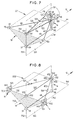
- first suspension member (48) linked on the one hand to the console (45) of the chassis (14) by means of a first articulation (49) of the ball-joint type, and on the other hand to a crosspiece (50) of the harvesting mechanism (19) by means of 'a second joint (51) also of the ball joint type.
- this second articulation (51) extends lower and, taking into account the direction of advance (12) at work, further back than the first articulation (49).
- the suspension device (22) further comprises a second suspension member (52) linked to the console (45) of the chassis (14) by means of a first articulation (53) of the cylindrical type with geometric axis (54). As it appears in FIG. 5, this first articulation (53) is even of the pivot type, that is to say a cylindrical articulation whose translation along its geometric axis is condemned.
- This second suspension member (52) is moreover linked to the inlet casing (40) of the harvesting mechanism (19) by means of a second articulation (55) of the ball type, which extends, as visible in Figure 2, below, and taking into account the direction of advance (12) at work, further back than the first articulation (53).
- This second suspension member (52) is arranged such that a first plane (56) (FIG.
- the geometric axis (54) of the first articulation (53) of the second suspension member (52) is arranged so that at work the first plane (56) is at least substantially directed in the direction of advance (12 ) at work. Here, it is even at least substantially coincident with the median plane (11) of the body (3), respectively of the harvesting mechanism (19).
- This second suspension member (52) is also also arranged so that its first articulation (53) extends higher and, taking into account the direction of advance (12) at work, further back than the first articulation (49) of the first suspension member (48).
- the second suspension member (52) thus extends higher than the first suspension member (48).
- This first suspension member (48) is, moreover, arranged so that, when the harvesting mechanism (19) rests on a horizontal ground (109), the center (59) of its second articulation (51) s' extends at least substantially in the foreground (56).
- the first joints (49; 53) and the second joints (51; 55) of the two suspension members (48; 52) are arranged in such a way that these two suspension members (48; 52) form with the chassis.
- the harvesting mechanism (19) at least substantially a deformable parallelogram in particular in the foreground (56).
- the first articulations (49; 53) extend, taking into account the direction of advance (12) at work, more forward than the second articulations (51; 55), said deformable parallelogram is pulled, which allows the harvesting mechanism (19) to pass well over obstacles.
- the suspension device (22) then comprises a first lateral suspension member (60) linked to the console (45) of the chassis (14) by means of a first articulation (61) of the ball-joint type, the center (62) of which is at least substantially situated on the geometric axis (54) of the first articulation (53) of the second suspension member (52), as well as at least substantially in the first plane (56).
- This first lateral suspension member (60) is moreover linked to the harvesting mechanism (19) by means of a second articulation (63) of the center ball type (64).
- the suspension device (22) then further comprises a second lateral suspension member (66) linked to the console (45) of the chassis (14) by means of a first articulation (67) of the ball type whose center (68) is at least substantially located on the geometric axis (54) of the first articulation (53) of the second member of suspension (52), as well as at least substantially in the foreground (56).
- a second lateral suspension member (66) linked to the harvesting mechanism (19) by means of a second articulation (69) of the center ball type (70).
- the two lateral suspension members (60, 66) are arranged in such a way that the centers (64, 70) of their second joints (63, 69), the center (57) of the second joint (55) of the second member suspension (52) and the combined centers (62, 68) of the first articulations (61, 67) of the two lateral suspension members (60, 66) are at least substantially situated in a second plane (71) which intersects the first plane ( 56) along a first straight line (72) passing through the center (57) of the second articulation (55) of the second suspension member (52) and the at least substantially coincident centers (62, 68) of the first articulations (61, 67 ) of the two lateral suspension members (60, 66).
- These two lateral suspension members (60, 66) are at least substantially symmetrical with respect to this first straight line (72).
- the centers (64, 70) of the second articulations (63, 69) of the two lateral suspension members (60, 66) and the center (57) of the second articulation (55) of the second suspension organ (52) are at least substantially located on a second straight line (73) which always remains at least substantially orthogonal to the first straight line (72).
- the harvesting mechanism (19) rests on a horizontal ground (109)
- the second plane (71) is at least substantially orthogonal to the first plane (56).
- the second straight line (73) therefore also extends at least substantially parallel to the geometric axis (54) of the first articulation (53) of the second member suspension (52).
- the second articulation (63) of the first lateral suspension member (60) extends - mower (1) seen from the rear in the direction of advance (12) at work - substantially in the middle part of the part of the harvesting mechanism (19) extending on the same side of the median plane (11) as said first lateral suspension member (60).
- the second articulation (63) of the first lateral suspension member (60) extends at a distance from the median plane (11) substantially equal to a quarter of the working width (65) of the harvesting mechanism ( 19).
- the second articulation (69) of the second lateral suspension member (66) also extends - mower (1) seen from the rear in the direction of advance (12) at work - substantially in the middle part of the part of the harvesting mechanism (19) extending on the same side of the median plane (11) as said second lateral suspension member (66).
- the suspension device (22) which has just been described, operates in the following manner.
- the harvesting mechanism (19) can move up and down relative to the chassis (14) by deformation of the deformable parallelogram formed by the two suspension members (48, 52) with the chassis (14) and the mechanism harvest (19).
- the harvesting mechanism (19) can then pivot around the first straight line (72).
- the harvesting mechanism (19) cannot, however, pivot around the straight line (74) passing through the center (58) of the first articulation (49) of the first suspension member (48) and the centers combined (62, 68 ) of the first articulations (61, 67) of the two lateral suspension members (60, 66).
- This pivoting is in fact condemned by the first articulation (53) of the second suspension member (52), given that the latter is of the cylindrical or pivot type.
- This first articulation (53) of the second suspension member (52) is therefore means preventing movement of the harvesting mechanism (19) transversely to the direction of advance (12) at work.
- the harvesting mechanism (19) can also not pivot about the straight line (75) passing through the centers (59, 57) of the second joints (51, 55) of the two suspension members (48, 52). This pivoting is in fact condemned by the two lateral suspension members (60, 66).
- the two suspension members (48, 52) and the two lateral suspension members (60, 66), constituting the suspension device (22), are each formed by a rigid connecting rod.
- the two lateral suspension members (60, 66) each comprise in particular a body (76, 77) one end of which is provided with a longitudinal threaded hole having a pitch to straight and the other end of which is provided with a longitudinal threaded hole having a pitch to the left.
- a suitable threaded rod (78, 79) in one of these threaded holes is screwed a suitable threaded rod (78, 79), while in the other threaded hole is also screwed a suitable threaded rod (80, 81).
- the length of the lateral suspension member (60, 66) is lengthened or narrowed.
- the rotation of the body (76, 77) relative to the threaded rods (78, 80, 79, 81) is condemned by means of a nut (82, 83) screwed onto the threaded rod (78 , 79) until it stops against the corresponding end of the body (76, 77). Thanks to these means, it is possible to correctly adjust the length of each lateral suspension member (60, 66). Thanks to these means, it is also possible to put each lateral suspension member (60, 66) under preload.
- the threaded rods (80, 81) of these lateral suspension members (60, 66) are rigidly linked to each other by means of a connecting plate (84) which extends under the first articulation (53) of the second suspension member (52).
- said connecting plate (84) is provided with a ball joint (85) intended to form both the first articulation (61) of the first lateral suspension member (60) and the first articulation (67) of the second lateral suspension member (66).
- each of the two wings (86, 87) of the console (45) of the chassis (14) is welded a ring (88, 89), so that these two rings (88, 89) define the geometric axis (54 ) of the first articulation (53) of the second suspension member (52).
- the latter in turn, has two cylindrical bearings (90, 91) extending at least substantially symmetrically relative to the foreground (56) and between which is provided a certain space (92) allowing the ball joint ( 85) to extend between said cylindrical bearing surfaces (90, 91).
- a pin (93) has a first part (94) having a diameter corresponding to the inside diameter of the ring (89) of the wing (87) of the console (45) and in which said first part (94) is housed.
- this first part (94) also passes through the cylindrical bearing surface (91) of the second suspension member (52), which is guided in rotation on said first part (94) by means of a guide ring (95).
- the pin (93) then comprises a second part (96) of a diameter less than the diameter of the first part (94), so as to form a shoulder (97) extending in the space (92) provided between the two cylindrical bearings (90, 91) of the second suspension member (52).
- the diameter of the second part (96) corresponds to the inside diameter of the ring (88) of the wing (86) of the console (45), in which said second part (96) is housed.
- the diameter of the second part (96) also corresponds to the inside diameter of the sphere (98) of the ball joint (85).
- the sphere (98) of the ball joint (85) is mounted on the second part (96) so as to extend between the shoulder (97) and a sheath (99) slipped on the second part (96) and s' extending between said sphere (98) and the ring (88).
- the outside diameter of this sheath (99) corresponds to the diameter of the first part (94) of the pin (93).
- This sleeve (99) additionally crosses the cylindrical surface (90) which is guided in rotation on said sleeve (99) by means of a guide ring (100).
- a threaded hole (101) is made along the longitudinal axis of the pin (93).
- a screw (102) which also passes through a support washer (103) extending between the head (104) of the screw (102) and the ring (88).
- the support washer (103) bears on the ring (88), which has the effect of displacing the pin (93) in the direction of said ring (88).
- the movement of the pin (93) will be stopped when the shoulder (97) abuts on the sphere (98) which abuts on the sleeve (99) which abuts on the ring (88).
- the sphere (98) is thus blocked and the body (105) of the ball joint (85) can pivot on the latter in order to form the first articulations (61, 67) of the two lateral suspension members (60, 66) .
- the external distance between the two cylindrical bearings (90, 91) is somewhat less than the internal distance (106) between the two rings (88, 89). In this way, said cylindrical bearings (90, 91) can pivot on the first part (94) of the journal (93), respectively on the sleeve (99), for the purpose of forming the first articulation (53) of the second member. suspension (52).
- first articulation (49) of the first suspension member (48) appears in detail on FIG. 6. It is however unnecessary to describe it, given that the ball joint (107), intended to form said first articulation (49), is mounted in the same way as the ball joint (85) forming the first articulations (61, 67) of the two lateral suspension members (60, 66), assembly which has been described above.
- the mower (1) further includes a lifting device (110) of the harvesting mechanism (19).
- This device consists of a hydraulic cylinder (111) whose cylinder (112) is linked to the chassis (14) and whose rod (113) is linked to a chain (114).
- This chain (114) is partially wound on a wheel (115) guided in rotation in the chassis (14), and is connected at its end remote from the hydraulic cylinder (111) to the second suspension member (52).
- this lifting device (110) does not hinder the movement of the harvesting mechanism (19) relative to the chassis (14).
- the harvesting mechanism (19) must be raised, it will suffice to bring the rod (113) into the body (112) of the hydraulic cylinder (111) by injecting fluid therein. In doing so, the rod (113) pulls, via the chain (114), on the second suspension member (52), which has the effect of raising the harvesting mechanism (19) by deformation of the deformable parallelogram.
- FIG. 7 schematically represents another exemplary embodiment of a suspension device (221).
- This comprises a first suspension member (48) identical to the first suspension member (48) of the suspension device (22).
- the latter consists of two elements (116, 117) each of which is linked to the chassis (14) by a first articulation (118, 119) of the ball-joint type and which are linked to the harvesting mechanism (19) by means of a second joint joint (551) of the patella type.
- the first two joints (118, 119) of the two elements (116, 117) form the first joint (531) by through which the second suspension member (521) is linked to the chassis (14).
- This first articulation (531) is equivalent to a pivot type articulation, the axis (541) of which is formed by the straight line passing through the centers (120, 121) of the first articulations (118, 119) of the two elements (116, 117).
- This second suspension member (521) is arranged such that a first plane (561), passing through the center (571) of its second articulation (551) and orthogonal to the geometric axis (541) of its first articulation (531), contains at least substantially the center (58) of the first articulation (49) of the first suspension member (48) and is at least substantially vertical.
- This first plane (561) also constitutes at least substantially the bisector plane of the angle formed by the two elements (116, 117) of the second suspension member (521).
- the geometric axis (541) of the first articulation (531) of the second suspension member (521) can be arranged so that at work, the first plane (561) is at least substantially directed in the direction of advance (12) at work. It can also be provided that the first plane (561) is at least substantially coincident with the median plane (11). Moreover, the first suspension member (48) is arranged such that when the harvesting mechanism (19) rests on a horizontal ground (109), the center (59) of its second articulation (51) extends to the less noticeably in the foreground (561).
- the relative position between the first joints (49, 531) and the second joints (51, 551) of the two suspension members (48, 521) is similar to that of the first joints (49, 53) and the second joints (51, 55) of the two suspension members (48, 52) of the suspension device (22).
- the two suspension members (48, 521) also form with the chassis (14) and the harvesting mechanism (19) at least substantially a drawn parallelogram.
- the suspension device (221) further comprises two lateral suspension members (60, 66) identical to those of the suspension device (22).
- the combined centers (62, 68) of their first articulations (61, 67) are at least substantially located on the geometric axis (541), as well as at least substantially in the foreground (561).
- the centers (64, 70) of their second articulations (63, 69), the center (571) of the second articulation (551) of the second suspension member (521) and the combined centers (62, 68) of the first articulations (61, 67) of the two lateral suspension members (60, 66) are at least substantially situated in a second plane (711) which intersects the first plane (561) along a first straight line (721) passing through the center ( 571) of the second articulation (551) of the second suspension member (521) and the at least substantially coincident centers (62, 68) of the first articulations (61, 67) of the two lateral suspension members (60, 66).
- the latter are at least substantially symmetrical with respect to this first straight line (721).
- the centers (64, 70) of the second articulations (63, 69) of the two lateral suspension members (60, 66) and the center (571) of the second articulation (551) of the second suspension organ (521) are at least substantially located on a second straight line (731) which always remains at least substantially orthogonal to the first straight line (721).
- the harvesting mechanism (19) rests on a horizontal ground (109)
- the second plane (711) is at least substantially orthogonal to the first plane (561).
- the second straight line (731) therefore also extends at least substantially parallel to the geometric axis (541) of the first articulation (531) of the second suspension member (521).
- the relative position of the second joints (63, 69) of the two lateral suspension members (60, 66) on the harvesting mechanism (19) is similar to that of the second joints (63, 69) of the two lateral suspension members (60, 66) of the suspension device (22).
- the two elements (116, 117) of the second suspension member (521) are each formed by a chain. These are also each provided with an adjustment member (122, 123) for the distance separating the center (120, 121) from their first articulation (118, 119) and the center (571) from their second articulation (551 ) common.
- the adjustment members (122, 123) mainly serve to put the elements (116, 117) under prestressing.
- This suspension device (221) operates in the following manner.
- the harvesting mechanism (19) can move up and down relative to the chassis (14) by deformation of the deformable parallelogram formed by the two suspension members (48, 521) with the chassis (14) and the mechanism harvest (19).
- the harvesting mechanism (19) can then pivot around the first straight line (721).
- the harvesting mechanism (19) cannot, however, pivot around the straight line (741) passing through the center (58) of the first articulation (49) of the first suspension member (48) and the centers combined (62, 68 ) of the first articulations (61, 67) of the two lateral suspension members (60, 66).
- This pivoting is in fact condemned by the first articulation (531) of the second suspension member (521), since the latter is of the pivot type.
- This first articulation (531) is therefore, like the first articulation (53), a means preventing the movement of the harvesting mechanism (19) in a direction transverse to the direction of advance (12) at work.
- the harvesting mechanism (19) cannot finally pivot around the straight line (751) passing through the centers (59, 571) of the second joints (51, 551) of the two suspension members (48, 521). This pivoting is in fact condemned by the two lateral suspension members (60, 66).
- FIG. 8 schematically represents another exemplary embodiment of a suspension device (222).
- This first comprises a first suspension member (48) identical to that of the suspension device (22).
- a second suspension member (522) linked on the one hand to the chassis (14) by means of a first articulation (532) of the ball-joint type and on the other hand to the harvesting mechanism (19) by means of a second articulation (552) also of the ball joint type.
- This second suspension member (522) is arranged so that the center (542) of its first articulation (532) and the center (572) of its second articulation (552) are located in at least one first plane (562) substantially vertical and passing through the center (58) of the first articulation (49) of the first suspension member (48).
- This first suspension member (48) is also arranged so that when the harvesting mechanism (19) rests on a horizontal ground (109), the center (59) of its second articulation (51) extends at least substantially in the foreground (562).
- the relative position between the first joints (49, 532) and the second joints (51, 552) of the two suspension members (48, 522) is similar to that of the first joints (49, 53) and the second joints (51, 55) of the two suspension members (48, 52) of the suspension device (22).
- the two suspension members (48, 522) also form with the chassis (14) and the harvesting mechanism (19) at least substantially a deformable parallelogram drawn.
- the suspension device (222) then comprises a first lateral suspension member (602) linked on the one hand to the chassis (14) by means of a first articulation (612) of the ball-joint type, the center (622) of which is at less substantially coincident with the center (542) of the first articulation (532) of the second suspension member (522), and on the other hand to the harvesting mechanism (19), by means of a second articulation (632) also of the ball type.
- the suspension device (222) then further comprises a second lateral suspension member (662) linked to the chassis (14) by means of a first articulation (672) of the ball-joint type, the center (682) of which is also at least substantially coincident with the center (542) of the first articulation (532) of the second suspension member (522).
- This second lateral suspension member (662) is on the other hand linked to the harvesting mechanism (19) by means of a second articulation (692) also of the ball joint type.
- the centers (642, 702) of the second articulations (632, 692) of the two lateral suspension members (602, 662), the center (572) of the second articulation (552) of the second suspension organ (522) and the combined centers (622, 682, 542) of the first articulations (612, 672, 532) of the two lateral suspension members (602, 662) and of the second suspension member (522) are at least substantially situated in a second plane (712) which cuts the first plane (562) along a first straight line (722) passing through the center (572) of the second articulation (552) of the second suspension member (522) and the centers at least substantially merged (622, 682, 542) of the first articulations (612, 672, 532) of the two lateral suspension members (602, 662), respectively of the second suspension member (522).
- the two lateral suspension members (602, 662) are at least substantially symmetrical with respect to this first straight line (722). Moreover, the centers (642, 702) of the second articulations (632, 692) of the two lateral suspension members (602, 662) and the center (572) of the second articulation (552) of the second suspension member (522) are at least substantially located on a second straight line (732) which always remains at least substantially orthogonal to the first straight line (722).
- the harvesting mechanism (19) rests on a horizontal ground (109)
- the second plane (712) is at least substantially orthogonal to the first plane (562).
- the position of the plane (562) relative to the direction of advance (12) at work is defined by stops (124, 125) integral with the chassis (14) and acting on the assembly formed by the second suspension member ( 522) and the two lateral suspension members (602, 662) or on the harvesting mechanism (19).
- These stops (124, 125) can be arranged so that at work the first plane (562) is at least substantially directed in the direction of advance (12) at work. It can also be provided that the first plane (562) is, like the first plane (56) of the suspension device (22), at least substantially coincident with the median plane (11).
- the second suspension member (522) is also formed by a rigid connecting rod.
- the two lateral suspension members (602, 662), on the other hand, are each formed by a cable. It appears, moreover, that these lateral suspension members (602, 662) are each provided with an adjustment member (126, 127) for the distance separating the center (622, 682) from their first articulation (612, 672 ) and the center (642, 702) of their second articulation (632, 692). These adjustment members (126, 127) are used in particular to put the lateral suspension members (602, 662) under pretension.
- the relative position of the second articulations (632, 692) of the two lateral suspension members (602, 662) on the harvesting mechanism (19) is similar to that of the second articulations (63, 69) of the two lateral suspension members (60, 66) of the suspension device (22).
- This suspension device (222) operates in the following manner.
- the harvesting mechanism (19) can move up and down relative to the chassis (14) by deformation of the deformable parallelogram formed by the two suspension members (48, 522) with the chassis (14) and the mechanism harvest (19).
- the harvesting mechanism (19) can then pivot around the first straight line (722).
- the harvesting mechanism (19) cannot, however, pivot or at least within a certain predetermined limit around the straight line (742) passing through the center (58) of the first articulation (49) of the first suspension member (48 ) and the combined centers (542, 622, 682) of the first joints (532, 612, 672) of the second suspension member (522) and of the two lateral suspension members (602, 662).
- This pivoting is in fact condemned or at least limited by the stops (124, 125) which are therefore a means preventing or limiting the movement of the harvesting mechanism (19) in a direction transverse to the direction of advance (12) at work .
- the harvesting mechanism (19) can also not pivot around the straight line (752) passing through the centers (59, 572) of the second joints (51, 552) of the two suspension members (48, 522). This pivoting is in fact condemned by the two lateral suspension members (602, 662).
- FIG. 9 schematically represents another exemplary embodiment of a suspension device (223).
- This suspension device (223) firstly comprises a suspension member (48) identical to the first suspension member (48) of the suspension device (22).
- This second suspension member (523) is arranged so that the center (543) of its first articulation (533) and the center (573) of its second articulation (553) are located in at least one first plane (563) substantially vertical and passing through the center (58) of the first articulation (49) of the first suspension member (48).
- This first suspension member (48) is also arranged so that when the harvesting mechanism (19) rests on a horizontal ground (109), the center (59) of its second articulation (51) extends at least substantially in the foreground (563).
- the relative position between the first joints (49, 553) and the second joints (51, 553) of the two suspension members (48, 523) is similar to that of the first joints (49, 53) and the second joints (51, 55) of the two suspension members (48, 52) of the suspension device (22).
- the two suspension members (48, 523) also form with the chassis (14) and the harvesting mechanism (19) at least substantially a deformable parallelogram drawn.
- the suspension device (223) then comprises a first lateral suspension member (603) linked on the one hand to the chassis (14) by means of a first articulation (613) of the ball-joint type, the center (623) of which is at less substantially coincident with the center (543) of the first articulation (533) of the second suspension member (523), and on the other hand to the harvesting mechanism (19) by means of a second articulation (633) also of the type patella.
- the suspension device (223) then further comprises a second lateral suspension member (663) linked to the chassis (14) by means of a first articulation (673) of the ball-joint type, the center (683) of which is also at least substantially coincident with the center (543) of the first articulation (533) of the second suspension member (523).
- This second lateral suspension member (663) is on the other hand linked to the harvesting mechanism (19) by means of a second articulation (693) also of the ball type.
- the centers (643, 703) of the second articulations (633, 693) of the two lateral suspension members (603, 663), the center (573) of the second articulation (553) of the second suspension organ (523) and the combined centers (623, 683, 543) of the first articulations (613, 673, 533) of the two lateral suspension members (603, 663) and of the second suspension member (523) are at least substantially situated in a second plane (713) which cuts the first plane (563) along a first straight line (723) passing through the center (573) of the second articulation (553) of the second suspension member (523) and the centers at least substantially merged (623, 683, 543) of the first articulations (613, 673, 533) of the two lateral suspension members (603, 663), respectively of the second suspension member (523).
- the two lateral suspension members (603, 663) are at least substantially symmetrical with respect to this first straight line (723). Moreover, the centers (643, 703) of the second articulations (633, 693) of the two lateral suspension members (603, 663) and the center (573) of the second articulation (553) of the second suspension organ (523) are at least substantially located on a second straight line (733) which always remains at least substantially orthogonal to the first straight line (723).
- the harvesting mechanism (19) rests on a horizontal ground (109)
- the second plane (713) is at least substantially orthogonal to the first plane (563).
- the second suspension member (523) is provided with a member (128), of section at least substantially square, which extends practically without play between two guide surfaces (130, 131) integral with the frame (14).
- These two guide surfaces (130, 131) are at least substantially planar and extend at least substantially parallel to the first plane (563). They thus allow said member (128) to move in the foreground (563).
- These guide surfaces (130, 131) can be arranged so that at work, the first plane (563) is at least substantially directed in the direction of advance (12) at work. It can also be provided that the first plane (563) is, like the first plane (56) of the suspension device (22), at least substantially coincident with the median plane (11).
- the second suspension member (523) as well as the two lateral suspension members (603, 663) to be rigid.
- these lateral suspension members (603, 663) may include adjustment members similar to those of the lateral suspension members (60, 66).
- the relative position of the second joints (633, 693) of the two lateral suspension members (603, 663) on the harvesting mechanism (19) is similar to that of the second joints (63, 69) of the two lateral suspension members (60, 66).
- This suspension device (223) operates in the following manner.
- the harvesting mechanism (19) can move up and down relative to the chassis (14) by deformation of the deformable parallelogram formed by the two suspension members (48, 523) with the chassis (14) and the mechanism harvest (19).
- the harvesting mechanism (19) can then pivot around the first straight line (723).
- the harvesting mechanism (19) cannot, on the other hand, not pivot or at least within a certain predetermined limit (if a clearance has been provided between the member (128) and the guide surfaces (130, 131)) around the straight line (743) passing through the center (58) of the first articulation (49) of the first suspension member (48) and the centers combined (543, 623, 683 ) of the first articulations (533, 613, 673) of the second suspension member (523) and of the two lateral suspension members (603, 663).
- This pivoting is in fact condemned or at least limited by the member (128) and the two guide surfaces (130, 131) which therefore constitute a means preventing or limiting the movement of the harvesting mechanism (19) in a direction transverse to the advance direction (12) at work.
- the harvesting mechanism (19) can also not pivot around the straight line (753) passing through the centers (59, 573) of the second joints (51, 553) of the two suspension members (48, 523). This pivoting is in fact condemned by the two lateral suspension members (603, 663).
- FIG. 10 schematically represents another exemplary embodiment of a suspension device (224).
- This suspension device (224) firstly comprises a suspension member (48) identical to the first suspension member (48) of the suspension device (22).
- the suspension device (224) then comprises a first lateral suspension member (604) linked on the one hand to the chassis (14) by means of a first articulation (614) of the ball-joint type and on the other hand to the harvesting mechanism. (19) by means of a second articulation (634) also of the ball joint type.
- the suspension device (224) then further comprises a second lateral suspension member (664) linked on the one hand to the chassis (14) by means of a first articulation (674) of the ball-joint type and on the other hand to the mechanism of harvest (19) by means of a second articulation (694) also of the ball type.
- a second articulation (694) also of the ball type.
- the centers (624, 684) of the first joints (614, 674) of the two lateral suspension members (604, 664) are at least substantially coincident. Near these latter, the two lateral suspension members (604, 664) are linked together by means of a cross-member (132).
- the latter carries a cylindrical finger (133) whose longitudinal axis (134) passes at least substantially through the at least substantially coincident centers (624, 684) of the first articulations (614, 674) of the two lateral suspension members (604 , 664).
- the longitudinal axis (134) of this cylindrical finger (133) thus forms with the center (58) of the first articulation (49) of the suspension member (48) a first plane (564) at least substantially vertical.
- the suspension member (48) is moreover arranged such that when the harvesting mechanism (19) rests on a horizontal ground (109), the center (59) of its second articulation (51) also extends to the less noticeably in the foreground (564)
- the centers (644, 704) of the second joints (634, 694) and the combined centers (624, 684) of the first joints (614, 674) of the two lateral suspension members (604, 664) are located in a second plane (714) which intersects the first plane (564) along a first straight line (724) at least substantially coincident with the longitudinal axis (134) of the cylindrical finger (133).
- the two lateral suspension members (604, 664) are at least substantially symmetrical with respect to this first straight line (724).
- the centers (644, 704) of the second articulations (634, 694) of the two lateral suspension members (604, 664) are located on a second straight line (734) which always remains at least substantially orthogonal to the first straight line ( 724).
- the second plane (714) is at least substantially orthogonal to the first plane (564).
- the position of the foreground (564) relative to the direction of advance (12) at work is defined by two guide surfaces (130, 131) identical to that of the suspension device (223) and between which extends the cylindrical finger (133). These therefore allow said cylindrical finger (133) to move in the plane (564) and to pivot around its longitudinal axis (134), that is to say around the first straight line (724).
- These guide surfaces (130, 131) can be arranged so that at work, the first plane (564) is at least substantially directed in the direction of advance (12) at work. It can also be provided that the first plane (564) is, like the first plane (56) of the suspension device (22), at least substantially coincident with the median plane (11).
- the relative position between the first joints (49, 614, 674) and the second joints (51, 634, 694) of the suspension member (48), respectively of the two lateral suspension members (604, 664), is identical to that of the first articulations (49, 61, 67) and of the second articulations (51, 63, 69) of the suspension member (48), respectively of the two lateral suspension members (60, 66) of the suspension device ( 22).
- the suspension member (48) and the two lateral suspension members (604, 664) thus form with the chassis (14) and the harvesting mechanism (19) a drawn parallelogram.
- the two lateral suspension members (604, 664) are rigid. Although this is not shown, it will be understood that these lateral suspension members (604, 664) may include adjustment members similar to those of the lateral suspension members (60, 66).
- the hanger (224) operates as follows.
- the harvesting mechanism (19) can move up and down relative to the chassis (14) by deformation of the deformable parallelogram defined above.
- the harvesting mechanism (19) can then pivot around the first straight line (724).
- the harvesting mechanism (19) cannot however pivot or at least within a certain predetermined limit around the straight line (744) passing through the center (58) of the first articulation (49) of the suspension member (48) and the combined centers (624, 684) of the first joints (614, 674) of the two lateral suspension members (604, 664).
- This pivoting is in fact condemned or at least limited by the cylindrical finger (133) and the two guide surfaces (130, 131) which therefore constitute a means preventing or limiting the movement of the harvesting mechanism (19) in a transverse direction to the advance direction (12) at work.
- the harvesting mechanism (19) can also not pivot around the straight line (754) passing through the center (59) of the second articulation (51) of the suspension member (48) and the point of intersection ( 135) of the first right (724) and the second right (734). This pivoting is in fact condemned by the two lateral suspension members (604, 664).
- At least one of the lateral suspension members (60, 66; 603, 663) could be replaced by one of the lateral suspension (602, 662) of the suspension device (222) and vice versa.
- the articulation (53) of the second suspension member (52) of the suspension device (22) could be replaced by the articulation (531) of the second suspension member (521) of the suspension device (221) and vice versa.
Landscapes
- Life Sciences & Earth Sciences (AREA)
- Environmental Sciences (AREA)
- Agricultural Machines (AREA)
- Soil Working Implements (AREA)
- Harvester Elements (AREA)
- Catching Or Destruction (AREA)
Applications Claiming Priority (2)
| Application Number | Priority Date | Filing Date | Title |
|---|---|---|---|
| FR8915684 | 1989-11-24 | ||
| FR8915684A FR2654893B1 (fr) | 1989-11-24 | 1989-11-24 | Machine agricole avec dispositif de suspension du groupe d'organes de travail perfectionne. |
Publications (2)
| Publication Number | Publication Date |
|---|---|
| EP0429381A1 EP0429381A1 (fr) | 1991-05-29 |
| EP0429381B1 true EP0429381B1 (fr) | 1995-03-01 |
Family
ID=9387898
Family Applications (1)
| Application Number | Title | Priority Date | Filing Date |
|---|---|---|---|
| EP90440106A Expired - Lifetime EP0429381B1 (fr) | 1989-11-24 | 1990-11-22 | Machine agricole avec dispositif de suspension du groupe d'organes de travail perfectionné |
Country Status (11)
| Country | Link |
|---|---|
| US (1) | US5107663A (da) |
| EP (1) | EP0429381B1 (da) |
| JP (1) | JP3204396B2 (da) |
| AT (1) | ATE118966T1 (da) |
| AU (1) | AU630006B2 (da) |
| CA (1) | CA2030765C (da) |
| DE (1) | DE69017362T2 (da) |
| DK (1) | DK0429381T3 (da) |
| ES (1) | ES2070300T3 (da) |
| FR (1) | FR2654893B1 (da) |
| RU (1) | RU2048718C1 (da) |
Families Citing this family (53)
| Publication number | Priority date | Publication date | Assignee | Title |
|---|---|---|---|---|
| DK26790A (da) * | 1990-02-01 | 1991-08-02 | Taarup As Maskinfab | Skaarlaegger |
| FR2668880B1 (fr) * | 1990-11-12 | 1995-06-30 | Kuhn Sa | Procede de transformation d'une machine de recolte pour l'amener d'une position de transport dans une position de travail, et machine de recolte. |
| FR2668881B1 (fr) * | 1990-11-12 | 1994-05-27 | Kuhn Sa | Machine agricole, en particulier faucheuse, s'adaptant aisement au relief du terrain et comportant un carter pivotant. |
| FR2696898B1 (fr) * | 1992-10-16 | 1994-12-09 | Kuhn Sa | Faucheuse avec un entraînement perfectionné des rouleaux de traitement. |
| DK170694B1 (da) * | 1993-03-08 | 1995-12-11 | Freudendahl J Fab As | Slåmaskine |
| DK170692B1 (da) * | 1993-03-08 | 1995-12-11 | Freudendahl J Fab As | Slåmaskine til høstning af græsafgrøder med to side om side indrettede slåaggregater |
| DK170693B1 (da) * | 1993-03-08 | 1995-12-11 | Freudendahl J Fab As | Slåmaskine |
| DK171261B1 (da) * | 1993-07-13 | 1996-08-19 | Freudendahl J Fab As | Slåmaskine omfattende to i forlængelse af hinanden liggende knivbjælker. |
| DE69520119T2 (de) * | 1994-04-21 | 2001-09-13 | Jf-Fabriken - J. Freudendahl A/S, Soenderborg | Gezogenes landwirtschaftliches Gerät |
| FR2724689B1 (fr) * | 1994-09-16 | 1997-01-24 | Kuhn Sa | Mecanisme de verrouillage destine a equiper principalement une machine agricole |
| FR2736505B1 (fr) * | 1995-07-13 | 1997-09-26 | Kuhn Sa | Faucheuse avec un dispositif d'andainage perfectionne |
| FR2743978B1 (fr) * | 1996-01-31 | 1998-04-17 | Kuhn Sa | Faucheuse avec organe de depose perfectionne |
| US6003291A (en) * | 1996-04-09 | 1999-12-21 | Kuhn, S.A. | Agriculture machine |
| FR2749127B1 (fr) * | 1996-05-28 | 1998-08-07 | Kuhn Sa | Machine de coupe de vegetaux, destinee a etre attelee a un vehicule moteur, avec un dispositif de verrouillage du mecanisme de coupe |
| FR2751166B1 (fr) * | 1996-07-22 | 1998-09-18 | Kuhn Sa | Machine agricole de recolte de vegetaux avec deux unites de conditionnement |
| FR2759531B1 (fr) * | 1997-02-14 | 1999-04-23 | Kuhn Sa | Machine agricole de coupe comportant un dispositif de suspension perfectionne du mecanisme de coupe |
| FR2759533B1 (fr) * | 1997-02-14 | 1999-04-23 | Kuhn Sa | Faucheuse comportant un dispositif empechant la transmission de tout ou partie des vibrations entre le mecanisme de coupe et la structure porteuse |
| FR2784003B1 (fr) | 1998-10-02 | 2000-12-29 | Kuhn Sa | Machine agricole comportant un timon pivotable et des organes de transmission comprenant un accouplement a joints universels |
| DE19818960B4 (de) * | 1998-04-28 | 2008-12-04 | Deere & Company, Moline | Aufhängung eines Vorsatzes |
| US6082085A (en) * | 1998-05-13 | 2000-07-04 | Agco Corporation | Foliage mowing implement having mechanical drive with main gearbox rotation |
| FR2786977B1 (fr) | 1998-12-14 | 2001-02-16 | Kuhn Sa | Faucheuse comportant un dispositif centralise de reglage de la force d'allegement exercee sur le mecanisme de recolte |
| FR2774853B1 (fr) | 1999-02-15 | 2001-02-16 | Kuhn Sa | Organe de coupe pour une machine de coupe notamment une faucheuse |
| FR2791224B1 (fr) | 1999-03-24 | 2001-05-25 | Kuhn Sa | Dispositif de coupe d'une machine de coupe, par exemple faucheuse comportant un dispositif d'entrainement du produit coupe |
| FR2792161B1 (fr) | 1999-04-16 | 2001-05-25 | Kuhn Sa | Machine de coupe comportant un dispositif de coupe lie a un chassis au moyen d'un dispositif de liaison ameliore |
| FR2792164B1 (fr) | 1999-04-16 | 2001-05-25 | Kuhn Sa | Dispositif de traitement de fourrage coupe et faucheuse utilisant un tel dispositif de traitement |
| FR2793379B1 (fr) | 1999-05-11 | 2001-07-06 | Kuhn Sa | Dispositif d'adaptation pour barre d'attelage de tracteur |
| FR2794206B1 (fr) | 1999-05-26 | 2001-07-06 | Kuhn Sa | Procede de montage/demontage et de reglage automatique de la tension d'un organe de transmission sans fin - machine agricole utilisant un tel procede |
| FR2823061B1 (fr) | 2001-04-06 | 2003-09-26 | Kuhn Sa | Machine de recolte avec un dispositif d'entrainement perfectionne |
| FR2823637A1 (fr) | 2001-04-18 | 2002-10-25 | Kuhn Sa | Faucheuse agricole comportant un mecanisme de regroupement d'andains |
| US6581362B2 (en) | 2001-06-19 | 2003-06-24 | Deere & Company | Crop converging arrangement for mower-conditioner equipped with a rotary disc cutter bar |
| US6655118B1 (en) | 2002-08-13 | 2003-12-02 | Vermeer Manufacturing Company | Suspension system |
| RU2261569C2 (ru) * | 2003-04-28 | 2005-10-10 | Кубанский государственный аграрный университет | Навесное устройство |
| WO2006011125A2 (en) * | 2004-07-26 | 2006-02-02 | Richard Murphy | A stabilising and release system for and boom holding and positioning system for an agricultural apparatus |
| FR2899430B1 (fr) * | 2006-04-11 | 2010-03-19 | Kuhn Sa | Rouleau conditionneur de faucheuse-conditionneuse, procede de fabrication d'un tel rouleau et faucheuse-conditionneuse equipee d'un tel rouleau |
| HU229564B1 (en) * | 2007-01-26 | 2014-02-28 | Optigep Kft | Harvest adapter equipped with stalk crusher for cereals, mainly for sunflower |
| US7726109B2 (en) | 2007-10-30 | 2010-06-01 | Vermeer Manufacturing Co. | Four-bar linkage for suspending a header for an agricultural implement |
| US7658056B2 (en) | 2007-10-30 | 2010-02-09 | Vermeer Manufacturing Co. | System for folding an agricultural machine with a floating work tool |
| BE1018757A3 (nl) * | 2009-05-15 | 2011-08-02 | Cnh Belgium Nv | Een oogstmachine met een bevestigingsinrichting voor een steunwiel en een methode voor het opbergen van een steunwiel van een oogstmachine. |
| US7823372B1 (en) * | 2009-06-22 | 2010-11-02 | Deere & Company | Skewed roller conveyor for double windrow attachment |
| US8261521B2 (en) * | 2009-08-31 | 2012-09-11 | Vermeer Manufacturing Company | Self-leveling four-bar linkage for suspending a header of an agricultural implement |
| PL2544519T3 (pl) * | 2010-03-12 | 2016-11-30 | Automatycznie sterowane przekładnie do urządzenia z dyszlem przegubowym | |
| DE102010041885A1 (de) * | 2010-10-01 | 2012-04-05 | Deere & Company | Kombination aus einem Zugfahrzeug und einem Gerät |
| FR2966322B1 (fr) * | 2010-10-21 | 2012-11-02 | Kuhn Sa | Machine de recolte avec un dispositif d'allegement |
| US8863489B2 (en) | 2011-03-30 | 2014-10-21 | H & S Manufacturing Co., Inc. | Tine drive cam for windrow merger |
| BE1020180A3 (nl) * | 2011-07-20 | 2013-06-04 | Cnh Belgium Nv | Maaidorser met messenrol. |
| US8418777B1 (en) * | 2011-12-09 | 2013-04-16 | GK Machine, Inc. | Agricultural folding scraper blade |
| US8752360B2 (en) * | 2011-12-28 | 2014-06-17 | Agco Corporation | Variable length header truss for harvesting header |
| US8857143B2 (en) * | 2011-12-28 | 2014-10-14 | Agco Corporation | Frame for harvesting header with continuous section |
| US9131638B2 (en) * | 2013-04-29 | 2015-09-15 | Cnh Industrial America Llc | Intermediate lift cylinder lock for extra tall stubble biomass operation |
| FR3013557B1 (fr) * | 2013-11-22 | 2016-01-01 | Kuhn Sa | Machine agricole, notamment machine pour la recolte de vegetaux, comportant deux unites de travail animees articulees a un meme bras lateral |
| US10375882B2 (en) * | 2017-04-19 | 2019-08-13 | Cnh Industrial America Llc | Multi-sectional header frame |
| CN108901355B (zh) * | 2018-06-11 | 2021-02-26 | 大连理工大学 | 一种基于变自由度机构的樱桃采摘装置 |
| US11266071B1 (en) | 2020-08-27 | 2022-03-08 | H & S Manufacturing Co., Inc. | Windrow merger with active weight transfer system |
Citations (1)
| Publication number | Priority date | Publication date | Assignee | Title |
|---|---|---|---|---|
| DE8701093U1 (de) * | 1987-01-23 | 1987-03-26 | Maschinenfabriken Bernard Krone Gmbh, 4441 Spelle | Traggestell für eine landwirtschaftliche Maschine |
Family Cites Families (14)
| Publication number | Priority date | Publication date | Assignee | Title |
|---|---|---|---|---|
| US2005618A (en) * | 1934-10-18 | 1935-06-18 | Int Harvester Co | Tractor cultivator |
| DE2019574C3 (de) * | 1970-04-23 | 1974-03-28 | Maschinenfabrik Fahr Ag Gottmadingen, 7702 Gottmadingen | Anordnung eines landwirtschaftlichen Arbeitsgerätes an einem Schlepper |
| DE2053073C3 (de) * | 1970-10-29 | 1981-01-29 | Maschinenfabriken Bernard Krone Gmbh, 4441 Spelle | Mähmaschine |
| GB1583983A (en) * | 1977-04-05 | 1981-02-04 | Sperry Ltd | Harvesting machines |
| GB1583982A (en) * | 1977-04-05 | 1981-02-04 | Sperry Ltd | Improvements in or relating to harvesting machines |
| GB2013466B (en) * | 1978-01-24 | 1982-06-03 | Sperry Rand France | Tractor mounted agricultural machine |
| US4177627A (en) * | 1978-06-12 | 1979-12-11 | International Harvester Company | Header suspension |
| FR2458981A1 (fr) * | 1979-06-19 | 1981-01-09 | Kuhn Sa | Bati de machine agricole |
| IT1133456B (it) * | 1979-07-13 | 1986-07-09 | Felten & Guilleaume Gmbh | Dispositivo antifurto per veicoli |
| FR2597293B1 (fr) * | 1986-04-17 | 1988-08-05 | Kuhn Sa | Faucheuse rotative avec barre de coupe et structure support. |
| NL8602865A (nl) * | 1986-11-12 | 1988-06-01 | Lely Nv C Van Der | Maaimachine. |
| FR2608362B1 (fr) * | 1986-12-22 | 1990-10-12 | Kuhn Sa | Faucheuse avec dispositif de suspension des groupes de fauche perfectionne |
| FR2614755A1 (fr) * | 1987-05-04 | 1988-11-10 | Kuhn Sa | Faucheuse munie d'un dispositif de reglage du piquage de l'organe de coupe |
| FR2617002B1 (fr) * | 1987-06-26 | 1991-06-07 | Kuhn Sa | Faucheuse munie de deux groupes d'organes de fauchage |
-
1989
- 1989-11-24 FR FR8915684A patent/FR2654893B1/fr not_active Expired - Fee Related
-
1990
- 1990-11-21 US US07/616,917 patent/US5107663A/en not_active Expired - Lifetime
- 1990-11-22 EP EP90440106A patent/EP0429381B1/fr not_active Expired - Lifetime
- 1990-11-22 DE DE69017362T patent/DE69017362T2/de not_active Expired - Fee Related
- 1990-11-22 DK DK90440106.4T patent/DK0429381T3/da active
- 1990-11-22 ES ES90440106T patent/ES2070300T3/es not_active Expired - Lifetime
- 1990-11-22 AT AT90440106T patent/ATE118966T1/de not_active IP Right Cessation
- 1990-11-23 RU SU904831669A patent/RU2048718C1/ru not_active IP Right Cessation
- 1990-11-23 CA CA002030765A patent/CA2030765C/fr not_active Expired - Fee Related
- 1990-11-23 AU AU66878/90A patent/AU630006B2/en not_active Ceased
- 1990-11-26 JP JP32222290A patent/JP3204396B2/ja not_active Expired - Fee Related
Patent Citations (1)
| Publication number | Priority date | Publication date | Assignee | Title |
|---|---|---|---|---|
| DE8701093U1 (de) * | 1987-01-23 | 1987-03-26 | Maschinenfabriken Bernard Krone Gmbh, 4441 Spelle | Traggestell für eine landwirtschaftliche Maschine |
Non-Patent Citations (1)
| Title |
|---|
| Prospektus Krone "faucheuse frontale à disques AFL". * |
Also Published As
| Publication number | Publication date |
|---|---|
| AU630006B2 (en) | 1992-10-15 |
| ATE118966T1 (de) | 1995-03-15 |
| FR2654893B1 (fr) | 1992-02-21 |
| EP0429381A1 (fr) | 1991-05-29 |
| DE69017362T2 (de) | 1995-10-26 |
| AU6687890A (en) | 1991-05-30 |
| JP3204396B2 (ja) | 2001-09-04 |
| ES2070300T3 (es) | 1995-06-01 |
| FR2654893A1 (fr) | 1991-05-31 |
| JPH03180105A (ja) | 1991-08-06 |
| DE69017362D1 (de) | 1995-04-06 |
| US5107663A (en) | 1992-04-28 |
| RU2048718C1 (ru) | 1995-11-27 |
| DK0429381T3 (da) | 1995-07-10 |
| CA2030765A1 (fr) | 1991-05-25 |
| CA2030765C (fr) | 2000-10-24 |
Similar Documents
| Publication | Publication Date | Title |
|---|---|---|
| CA2030765C (fr) | Machine agricole avec dispositif de suspension du groupe d'organes de travail perfectionne | |
| CA2030728C (fr) | Faucheuse avec dispositif d'allegement perfectionne | |
| EP0211785B1 (fr) | Faucheuse | |
| EP0297012B1 (fr) | Faucheuse rotative | |
| CA2030764C (fr) | Faucheuse comportant un groupe d'organes de travail s'etendant au travail transversalement a la direction d'avance | |
| CA1253697A (fr) | Faucheuse | |
| EP0356358B1 (fr) | Faucheuse à châssis perfectionné | |
| CA2226656C (fr) | Machine agricole de coupe perfectionnee | |
| FR2628596A1 (fr) | Faucheuse a entrainement direct | |
| EP0461056B1 (fr) | Machine agricole comportant deux organes liés entre eux au moyen d'une articulation protégée | |
| FR2760934A1 (fr) | Dispositif d'orientation de la boite a engrenages d'une moissonneuse conditionneuse | |
| EP0763321A1 (fr) | Machine de fenaison | |
| FR2806871A1 (fr) | Machine de fenaison comportant au moins une roue rateleuse articulee sur un bras porteur | |
| EP3973757B1 (fr) | Machine agricole trainée ou semi-portée avec un dispositif d'essieu réglable | |
| EP0779022B1 (fr) | Machine de fenaison | |
| FR2759245A1 (fr) | Machine de fenaison avec un dispositif d'appui au sol incluant au moins un balancier avec deux roues porteuses et un moyen pour deplacer ce balancier en vue du transport | |
| FR2644029A1 (fr) | Dispositif d'attelage pivotant pour outil agricole de grande largeur | |
| EP1111986B1 (fr) | Dispositif de roulement pour engin agricole | |
| EP0733302B1 (fr) | Machine de fenaison | |
| EP0654209B1 (fr) | Machine de fenaison | |
| EP3973756B1 (fr) | Machine agricole trainée de récolte avec un essieu réglable | |
| FR2551016A1 (da) | ||
| EP0486415B1 (fr) | Faucheuse à châssis indépendant comportant un dispositif de suspension et un dispositif d'allègement perfectionnés | |
| EP1449418A1 (fr) | Charrue réversible semi-portée | |
| FR2853204A1 (fr) | Machine agricole portee comportant au moins une roue d'assistance au transport |
Legal Events
| Date | Code | Title | Description |
|---|---|---|---|
| PUAI | Public reference made under article 153(3) epc to a published international application that has entered the european phase |
Free format text: ORIGINAL CODE: 0009012 |
|
| AK | Designated contracting states |
Kind code of ref document: A1 Designated state(s): AT BE DE DK ES FR GB IT NL SE |
|
| 17P | Request for examination filed |
Effective date: 19911009 |
|
| 17Q | First examination report despatched |
Effective date: 19921009 |
|
| GRAA | (expected) grant |
Free format text: ORIGINAL CODE: 0009210 |
|
| AK | Designated contracting states |
Kind code of ref document: B1 Designated state(s): AT BE DE DK ES FR GB IT NL SE |
|
| REF | Corresponds to: |
Ref document number: 118966 Country of ref document: AT Date of ref document: 19950315 Kind code of ref document: T |
|
| REF | Corresponds to: |
Ref document number: 69017362 Country of ref document: DE Date of ref document: 19950406 |
|
| ITF | It: translation for a ep patent filed | ||
| PG25 | Lapsed in a contracting state [announced via postgrant information from national office to epo] |
Ref country code: SE Effective date: 19950601 |
|
| REG | Reference to a national code |
Ref country code: ES Ref legal event code: FG2A Ref document number: 2070300 Country of ref document: ES Kind code of ref document: T3 |
|
| GBT | Gb: translation of ep patent filed (gb section 77(6)(a)/1977) |
Effective date: 19950605 |
|
| REG | Reference to a national code |
Ref country code: DK Ref legal event code: T3 |
|
| PG25 | Lapsed in a contracting state [announced via postgrant information from national office to epo] |
Ref country code: BE Effective date: 19951130 |
|
| PLBE | No opposition filed within time limit |
Free format text: ORIGINAL CODE: 0009261 |
|
| STAA | Information on the status of an ep patent application or granted ep patent |
Free format text: STATUS: NO OPPOSITION FILED WITHIN TIME LIMIT |
|
| 26N | No opposition filed | ||
| BERE | Be: lapsed |
Owner name: S.A. KUHN Effective date: 19951130 |
|
| REG | Reference to a national code |
Ref country code: GB Ref legal event code: IF02 |
|
| PGFP | Annual fee paid to national office [announced via postgrant information from national office to epo] |
Ref country code: NL Payment date: 20071026 Year of fee payment: 18 Ref country code: ES Payment date: 20071108 Year of fee payment: 18 Ref country code: DE Payment date: 20071113 Year of fee payment: 18 Ref country code: DK Payment date: 20071025 Year of fee payment: 18 |
|
| PGFP | Annual fee paid to national office [announced via postgrant information from national office to epo] |
Ref country code: IT Payment date: 20071117 Year of fee payment: 18 |
|
| PGFP | Annual fee paid to national office [announced via postgrant information from national office to epo] |
Ref country code: FR Payment date: 20071129 Year of fee payment: 18 Ref country code: GB Payment date: 20071029 Year of fee payment: 18 |
|
| PGFP | Annual fee paid to national office [announced via postgrant information from national office to epo] |
Ref country code: AT Payment date: 20081023 Year of fee payment: 19 |
|
| REG | Reference to a national code |
Ref country code: DK Ref legal event code: EBP |
|
| GBPC | Gb: european patent ceased through non-payment of renewal fee |
Effective date: 20081122 |
|
| PG25 | Lapsed in a contracting state [announced via postgrant information from national office to epo] |
Ref country code: NL Free format text: LAPSE BECAUSE OF NON-PAYMENT OF DUE FEES Effective date: 20090601 |
|
| NLV4 | Nl: lapsed or anulled due to non-payment of the annual fee |
Effective date: 20090601 |
|
| PG25 | Lapsed in a contracting state [announced via postgrant information from national office to epo] |
Ref country code: IT Free format text: LAPSE BECAUSE OF NON-PAYMENT OF DUE FEES Effective date: 20081122 |
|
| REG | Reference to a national code |
Ref country code: FR Ref legal event code: ST Effective date: 20090731 |
|
| PG25 | Lapsed in a contracting state [announced via postgrant information from national office to epo] |
Ref country code: DK Free format text: LAPSE BECAUSE OF NON-PAYMENT OF DUE FEES Effective date: 20081130 Ref country code: DE Free format text: LAPSE BECAUSE OF NON-PAYMENT OF DUE FEES Effective date: 20090603 |
|
| PG25 | Lapsed in a contracting state [announced via postgrant information from national office to epo] |
Ref country code: GB Free format text: LAPSE BECAUSE OF NON-PAYMENT OF DUE FEES Effective date: 20081122 |
|
| REG | Reference to a national code |
Ref country code: ES Ref legal event code: FD2A Effective date: 20081124 |
|
| PG25 | Lapsed in a contracting state [announced via postgrant information from national office to epo] |
Ref country code: ES Free format text: LAPSE BECAUSE OF NON-PAYMENT OF DUE FEES Effective date: 20081124 |
|
| PG25 | Lapsed in a contracting state [announced via postgrant information from national office to epo] |
Ref country code: AT Free format text: LAPSE BECAUSE OF NON-PAYMENT OF DUE FEES Effective date: 20091122 |
|
| PG25 | Lapsed in a contracting state [announced via postgrant information from national office to epo] |
Ref country code: FR Free format text: LAPSE BECAUSE OF NON-PAYMENT OF DUE FEES Effective date: 20081130 |