EP0429413B1 - Articulation avec joint hydraulique tournant, en particulier pour machines mobiles de travaux publics - Google Patents
Articulation avec joint hydraulique tournant, en particulier pour machines mobiles de travaux publics Download PDFInfo
- Publication number
- EP0429413B1 EP0429413B1 EP90830534A EP90830534A EP0429413B1 EP 0429413 B1 EP0429413 B1 EP 0429413B1 EP 90830534 A EP90830534 A EP 90830534A EP 90830534 A EP90830534 A EP 90830534A EP 0429413 B1 EP0429413 B1 EP 0429413B1
- Authority
- EP
- European Patent Office
- Prior art keywords
- hollow internal
- internal body
- articulation
- external
- reduction gear
- Prior art date
- Legal status (The legal status is an assumption and is not a legal conclusion. Google has not performed a legal analysis and makes no representation as to the accuracy of the status listed.)
- Expired - Lifetime
Links
- 239000007787 solid Substances 0.000 claims description 8
- 239000012530 fluid Substances 0.000 claims description 3
- 230000003042 antagnostic effect Effects 0.000 claims description 2
- 230000005540 biological transmission Effects 0.000 claims description 2
- 230000008878 coupling Effects 0.000 abstract 1
- 238000010168 coupling process Methods 0.000 abstract 1
- 238000005859 coupling reaction Methods 0.000 abstract 1
- 239000003638 chemical reducing agent Substances 0.000 description 2
- 238000010586 diagram Methods 0.000 description 1
Images

Classifications
-
- B—PERFORMING OPERATIONS; TRANSPORTING
- B66—HOISTING; LIFTING; HAULING
- B66C—CRANES; LOAD-ENGAGING ELEMENTS OR DEVICES FOR CRANES, CAPSTANS, WINCHES, OR TACKLES
- B66C23/00—Cranes comprising essentially a beam, boom, or triangular structure acting as a cantilever and mounted for translatory of swinging movements in vertical or horizontal planes or a combination of such movements, e.g. jib-cranes, derricks, tower cranes
- B66C23/62—Constructional features or details
- B66C23/84—Slewing gear
- B66C23/86—Slewing gear hydraulically actuated
-
- E—FIXED CONSTRUCTIONS
- E02—HYDRAULIC ENGINEERING; FOUNDATIONS; SOIL SHIFTING
- E02F—DREDGING; SOIL-SHIFTING
- E02F9/00—Component parts of dredgers or soil-shifting machines, not restricted to one of the kinds covered by groups E02F3/00 - E02F7/00
- E02F9/08—Superstructures; Supports for superstructures
- E02F9/10—Supports for movable superstructures mounted on travelling or walking gears or on other superstructures
- E02F9/12—Slewing or traversing gears
- E02F9/121—Turntables, i.e. structure rotatable about 360°
Definitions
- the invention relates to an articulation with rotating hydraulic connection, in particular for mobile work machines.
- This kind of articulation performs the task of reciprocally connecting two parts of the machine permitting the unlimited two-way rotation of the one with regard to the other.
- some types of mobile work machine such as for example articulated-arm diggers and cranes, on which a hydraulically-activated articulated arm is placed on a rotatable platform which is pivoted normally about a vertical axis.
- the articulation between the two parts is normally effected by means of a bearing of considerable diameter on one part of which a crown wheel is arranged which meshes with a sprocket on the other part which is commanded to rotate by a fixed motor reducer, evidently eccentrically disposed with respect to the rotation axis.
- the rotating joint completely separated from the bearing, but coaxially situated with respect to it, ensures the hydraulic connection between the components of the hydraulic circuit situated on the two parts of the machine.
- the other negative characteristic relates to the mass and weight of the solutions embraced in the prior art.
- the document FR-A- 1 553 597 shows an articulation with rotating hydraulic connection, in particular for mobile work machines which comprises :
- the present invention seeks to obviate the drawbacks and shortcomings in the prior art, with an articulation with rotating hydraulic connection which groups together in a single compact device the principal articulation components.
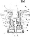
- fig 1 shows the external body of an articulation with rotating hydraulic connection able to be solidly mounted on one of the two parts reciprocally connected by the articulation; for example, in the case of a mobile work machine, to the wheel-mounted frame.
- the external body 1 is equipped on its upper part with a flange 23 having through bores 24 for connection by means of bolts.
- the external body 1 has beneath the flange 23 an internal cylindrical surface 3 having annular channels 2 in communication with an external conduit 30.
- a hollow internal body 4 is coaxially and rotatingly coupled to the external body 1 and has an internal cylindrical surface 5 shaped and arranged to be in face-on contact with the internal cylindrical surface 3.
- the open ends 6 of hydraulic conduits 7 envisaged solidly in the hollow internal body 4 are arranged in correspondence with the external cylindrical surface 5.
- Each hydraulic conduit 7 has an open end 6 located in such a way that it faces one of the annular channels 2 bored into the external body 1.
- the rotating seal between the annular channels 2 and the open ends 6 is circumferentially guaranteed by seals 25.
- the hollow internal body 4 is supported to the external body 1 by means of bearings 26 and 27.
- a hydraulic motor 8 is fixed to the hollow internal body 4, which is axialsymmetric in form and has in its upper part a flange 28 for its connection with the upper part of the machine.
- the hydraulic motor 8 housed in the internal cavity of the hollow internal body 4, activates a shaft 9 which is arranged coaxially with the cylindrical surfaces 3 and 5 and is engaged to the hollow internal body 4 by means of a hydraulically activated clutch 10.
- the clutch 10 is of the disk-type and is kept in the engaged position by a system of coaxial springs 11 which act upon a disk collar 12 with antagonistic action with respect to that of the pressurised fluid introduced into the annular channel 13 of a jack, whose annular piston 14 is coaxially slidable and sealed inside a cylindrical chamber 15 bored coaxially in the hollow internal body 4.
- the shaft 9 is the drive-shaft of an epicyclic reduction gear, indicated by 16, which reciprocally connects the hollow internal body 4 with the external body 1.
- the epicyclic reduction gear 16 comprises a satellite carrier 17 which is solid to the hollow internal body 4 and an internally cogged crown wheel 18, to which the satellites 19 mesh, solid to the external body 1 and arranged coaxially to the rotation axis of the shaft 9.
- the clutch 10 is kept in the engaged position by the action of the springs 11. Disengagement is performed by sending pressurised fluid into the chamber 13 whenever the rotation command is activated to produce rotation in either direction of the hollow internal body 4 with respect to the external body 1. In this situation the shaft 9 is free to rotate with respect to the hollow internal body 4 and thus to produce the rotation of the latter with respect to the external body 1 according to the reduction rapport of the epicyclic reduction gear 16.
- the group is extremely compact, without substantial limits to transmission power and to the number of rotating hydraulic connections between the two mobile parts of the articulation.
- a more normal reduction gear 20 is arranged, in which the chassis 21 is solid to the hollow internal body 4 while the conduit shaft 22 is mounted to the external body 1 and coaligned with the drive shaft 9.
- Both illustrated embodiments are characterised by extreme compactness and permit of great ease and rationality of assembly and dissembly.
Landscapes
- Engineering & Computer Science (AREA)
- Mechanical Engineering (AREA)
- Mining & Mineral Resources (AREA)
- Civil Engineering (AREA)
- General Engineering & Computer Science (AREA)
- Structural Engineering (AREA)
- Quick-Acting Or Multi-Walled Pipe Joints (AREA)
- Joints Allowing Movement (AREA)
- Hydraulic Motors (AREA)
- Retarders (AREA)
- Gear Transmission (AREA)
- Component Parts Of Construction Machinery (AREA)
Claims (3)
- Une articulation avec joint hydraulique tournant, en particulier pour machines mobiles de travaux publics qui comprend:- un corps extérieur (1) qui a, en correspondance avec sa propre surface cylindrique interne (3), les rainures annulaires (2) dudit joint;- un corps intérieur creux (4) qui est supporté et accouplé d'une manière coaxiale et tournante audit corps extérieur (1) et qui a une surface cylindrique externe (5); sur cette surface (5) sont situées les extrémités ouvertes (6) de différents conduits hydrauliques (7), ces extrémités ouvertes (6) se présentant sur lesdites rainures annulaires (2); ledit corps intérieur creux (4) ayant un moteur hydraulique (8) fixé sur lui pour produire le mouvement de rotation par rapport audit corps extérieur (1);- un moteur de transmission, qui comprend: un arbre de commande (9) mis en action directement par ledit moteur hydraulique (8), disposé coaxialement aux surfaces cylindriques (3) et (5); un engrenage démultiplicateur (16) coaxial qui relie réciproquement le corps extérieur (1) avec le corps intérieur creux (4) et qui a, comme arbre de commande, ledit arbre (9);
caractérisé en ce fait que ledit moteur hydraulique (8) est placé dans la cavité interne dudit corps intérieur creux (4) et que ledit arbre de commande (9) peut être embrayé audit corps intérieur creux (4) au moyen d'un embrayage (10) qui peut être désembrayé hydrauliquement et qui est du type à disque et qui est tenu dans la position engrenée par un système de ressorts coaxiaux (11) qui agissent sur un collier du disque (12) avec une action antagoniste par rapport à celle du fluide pressurisé qui est introduit dans le canal annulaire (13) d'un vérin hydraulique, dont le piston annulaire (14), qui peut glisser d'une façon coaxiale et qui est scellé à l'intérieur de la chambre cylindrique (15) trouée coaxialement dans le corps intérieur creux (4), est d'un seul tenant avec le collier du disque (12). - Une articulation comme celle de la revendication 1, dans laquelle ledit engrenage démultiplicateur est un engrenage démultiplicateur épicycloïdal (16) dans lequel l'arbre de commande (9) est d'un seul tenant avec l'arbre du moteur, le porteur de satellite (17) est d'un seul tenant avec le corps intérieur creux (4) et la roue de la couronne endentée à l'intérieur (18), avec laquelle les satellites (19) s'engrènent, est d'un seul tenant avec le corps extérieur (1).
- Une articulation comme celle de la revendication 1, dans laquelle ledit engrenage démultiplicateur est un engrenage démultiplicateur (20) avec au moins deux phases dans lesquelles le châssis (21) est d'un seul tenant avec le corps intérieur creux (4) et l'arbre de conduite (22) est fixé au corps extérieur (1) coaxialement à l'arbre de commande (9).
Applications Claiming Priority (2)
| Application Number | Priority Date | Filing Date | Title |
|---|---|---|---|
| IT04017589A IT1236282B (it) | 1989-11-20 | 1989-11-20 | Articolazione con collegamento idraulico rotante in particolare per macchine operatrici. |
| IT4017589 | 1989-11-20 |
Publications (2)
| Publication Number | Publication Date |
|---|---|
| EP0429413A1 EP0429413A1 (fr) | 1991-05-29 |
| EP0429413B1 true EP0429413B1 (fr) | 1994-06-08 |
Family
ID=11248963
Family Applications (1)
| Application Number | Title | Priority Date | Filing Date |
|---|---|---|---|
| EP90830534A Expired - Lifetime EP0429413B1 (fr) | 1989-11-20 | 1990-11-19 | Articulation avec joint hydraulique tournant, en particulier pour machines mobiles de travaux publics |
Country Status (5)
| Country | Link |
|---|---|
| EP (1) | EP0429413B1 (fr) |
| AT (1) | ATE106850T1 (fr) |
| DE (1) | DE69009691T2 (fr) |
| ES (1) | ES2057518T3 (fr) |
| IT (1) | IT1236282B (fr) |
Families Citing this family (7)
| Publication number | Priority date | Publication date | Assignee | Title |
|---|---|---|---|---|
| DE9400767U1 (de) * | 1994-01-18 | 1994-04-28 | Ec Engineering + Consulting Spezialmaschinen Gmbh, 89079 Ulm | Drehdurchführung |
| DE10025693A1 (de) * | 2000-05-24 | 2001-11-29 | Zahnradfabrik Friedrichshafen | Drehwerkantrieb |
| DE10309258B4 (de) * | 2003-03-03 | 2006-10-12 | Archimedes Voulgaris Hydraulikmotorenbau Gmbh | Einrichtung zur Befestigung und zum Drehantrieb eines Greiferwerkzeugs |
| DE102004010300A1 (de) * | 2004-03-03 | 2005-09-22 | Linde Ag | Drehwerksantrieb in Zentralbauweise |
| RU2468983C1 (ru) * | 2011-05-31 | 2012-12-10 | Федеральное государственное автономное образовательное учреждение высшего профессионального образования Сибирский федеральный университет (СФУ) | Поворотное устройство несущей стойки гидроманипулятора |
| JP5980711B2 (ja) * | 2013-03-29 | 2016-08-31 | 住友重機械工業株式会社 | ショベル |
| SE547879C2 (en) * | 2023-11-14 | 2025-12-16 | Indexator Rotator Sys Ab | Rotator for carrying a hydraulic tool and a vehicle comprising a rotor |
Family Cites Families (9)
| Publication number | Priority date | Publication date | Assignee | Title |
|---|---|---|---|---|
| GB1019687A (en) * | 1963-10-03 | 1966-02-09 | Bergens Mek Verksted | Arrangement for pivoting the derrick or extension arm in a crane, especially a ship's crane |
| FR1553597A (fr) * | 1967-03-01 | 1969-01-10 | ||
| US3662623A (en) * | 1970-08-19 | 1972-05-16 | Lorence Mfg Corp | Turntable drive mechanism |
| FR2122294B1 (fr) * | 1971-01-18 | 1975-06-06 | Poclain Sa | |
| US3819018A (en) * | 1972-12-04 | 1974-06-25 | Caterpillar Tractor Co | Brake assembly for excavator swing transmission |
| US3877743A (en) * | 1973-06-25 | 1975-04-15 | Norman Allen Johnson | Fluid operated grapple |
| US4009643A (en) * | 1975-02-26 | 1977-03-01 | Heinz Thumm | Hydraulic motor for rotating the bucket of an excavating machine |
| DE3135150C1 (de) * | 1981-09-04 | 1983-01-13 | Liebherr-Hydraulikbagger Gmbh, 7951 Kirchdorf | Kupplung zum Ankuppeln von Arbeitsgeräten an Stiele von Hydraulikbaggern |
| US4426110A (en) * | 1981-09-17 | 1984-01-17 | Mar Hook & Equipment, Inc. | Continuous rotation hydraulic grapple |
-
1989
- 1989-11-20 IT IT04017589A patent/IT1236282B/it active IP Right Grant
-
1990
- 1990-11-19 ES ES90830534T patent/ES2057518T3/es not_active Expired - Lifetime
- 1990-11-19 AT AT90830534T patent/ATE106850T1/de not_active IP Right Cessation
- 1990-11-19 EP EP90830534A patent/EP0429413B1/fr not_active Expired - Lifetime
- 1990-11-19 DE DE69009691T patent/DE69009691T2/de not_active Expired - Fee Related
Also Published As
| Publication number | Publication date |
|---|---|
| IT8940175A0 (it) | 1989-11-20 |
| EP0429413A1 (fr) | 1991-05-29 |
| ATE106850T1 (de) | 1994-06-15 |
| IT1236282B (it) | 1993-02-02 |
| DE69009691D1 (de) | 1994-07-14 |
| ES2057518T3 (es) | 1994-10-16 |
| IT8940175A1 (it) | 1991-05-20 |
| DE69009691T2 (de) | 1994-10-20 |
Similar Documents
| Publication | Publication Date | Title |
|---|---|---|
| US4431073A (en) | Two speed final drive gear box | |
| US4499790A (en) | Swivel head for industrial robots | |
| FI93264B (fi) | Hydrostaattismekaaninen tehonhaaroitusvaihteisto | |
| EP0636814B1 (fr) | yransmission mécanique pour roues motrices, en particulier pour engin de travail mobile | |
| EP0429413B1 (fr) | Articulation avec joint hydraulique tournant, en particulier pour machines mobiles de travaux publics | |
| US7074149B2 (en) | Transmission for wheel type working vehicle | |
| US12480276B2 (en) | Electric cylinder and work machine | |
| US4177869A (en) | Swivel joint for a vehicle | |
| US2343800A (en) | Vehicle construction | |
| US3736993A (en) | High torque boring machine | |
| EP0305548B1 (fr) | Moteur hydraulique a capacite variable | |
| USRE31500E (en) | Material-handling vehicle | |
| GB2131390A (en) | Automatic handling implement for industrial operations | |
| US5148885A (en) | Steerable utility vehicle | |
| US2949162A (en) | Carriage and driving mechanism for a mobile boom machine | |
| US3391753A (en) | Fluid power wheel | |
| US6742954B2 (en) | Locking system for a rotating joint | |
| US5356351A (en) | Shuttlecar wheel end | |
| US3915321A (en) | Front end loader | |
| CN223447570U (zh) | 一种双动力多式驱动减速传动装置 | |
| CN219309684U (zh) | 一种鞍座可任意角度旋转的钢卷小车 | |
| JPH0251561B2 (fr) | ||
| CN219217468U (zh) | 一种用于作业斗回转的驱动机构 | |
| EP1020397A2 (fr) | Montage de roue | |
| SU1556945A1 (ru) | Механизм привода вала отбора мощности транспортного средства |
Legal Events
| Date | Code | Title | Description |
|---|---|---|---|
| PUAI | Public reference made under article 153(3) epc to a published international application that has entered the european phase |
Free format text: ORIGINAL CODE: 0009012 |
|
| AK | Designated contracting states |
Kind code of ref document: A1 Designated state(s): AT DE ES FR GB |
|
| 17P | Request for examination filed |
Effective date: 19911008 |
|
| 17Q | First examination report despatched |
Effective date: 19930423 |
|
| RAP1 | Party data changed (applicant data changed or rights of an application transferred) |
Owner name: VANZINI, ODDONE |
|
| GRAA | (expected) grant |
Free format text: ORIGINAL CODE: 0009210 |
|
| AK | Designated contracting states |
Kind code of ref document: B1 Designated state(s): AT DE ES FR GB |
|
| REF | Corresponds to: |
Ref document number: 106850 Country of ref document: AT Date of ref document: 19940615 Kind code of ref document: T |
|
| REF | Corresponds to: |
Ref document number: 69009691 Country of ref document: DE Date of ref document: 19940714 |
|
| ET | Fr: translation filed | ||
| REG | Reference to a national code |
Ref country code: ES Ref legal event code: FG2A Ref document number: 2057518 Country of ref document: ES Kind code of ref document: T3 |
|
| PLBE | No opposition filed within time limit |
Free format text: ORIGINAL CODE: 0009261 |
|
| STAA | Information on the status of an ep patent application or granted ep patent |
Free format text: STATUS: NO OPPOSITION FILED WITHIN TIME LIMIT |
|
| 26N | No opposition filed | ||
| PGFP | Annual fee paid to national office [announced via postgrant information from national office to epo] |
Ref country code: GB Payment date: 19981120 Year of fee payment: 9 |
|
| PGFP | Annual fee paid to national office [announced via postgrant information from national office to epo] |
Ref country code: FR Payment date: 19981125 Year of fee payment: 9 |
|
| PGFP | Annual fee paid to national office [announced via postgrant information from national office to epo] |
Ref country code: AT Payment date: 19981127 Year of fee payment: 9 |
|
| PGFP | Annual fee paid to national office [announced via postgrant information from national office to epo] |
Ref country code: ES Payment date: 19981130 Year of fee payment: 9 Ref country code: DE Payment date: 19981130 Year of fee payment: 9 |
|
| PG25 | Lapsed in a contracting state [announced via postgrant information from national office to epo] |
Ref country code: GB Free format text: LAPSE BECAUSE OF NON-PAYMENT OF DUE FEES Effective date: 19991119 Ref country code: AT Free format text: LAPSE BECAUSE OF NON-PAYMENT OF DUE FEES Effective date: 19991119 |
|
| PG25 | Lapsed in a contracting state [announced via postgrant information from national office to epo] |
Ref country code: ES Free format text: LAPSE BECAUSE OF NON-PAYMENT OF DUE FEES Effective date: 19991120 |
|
| GBPC | Gb: european patent ceased through non-payment of renewal fee |
Effective date: 19991119 |
|
| PG25 | Lapsed in a contracting state [announced via postgrant information from national office to epo] |
Ref country code: FR Free format text: LAPSE BECAUSE OF NON-PAYMENT OF DUE FEES Effective date: 20000731 |
|
| PG25 | Lapsed in a contracting state [announced via postgrant information from national office to epo] |
Ref country code: DE Free format text: LAPSE BECAUSE OF NON-PAYMENT OF DUE FEES Effective date: 20000901 |
|
| REG | Reference to a national code |
Ref country code: FR Ref legal event code: ST |
|
| REG | Reference to a national code |
Ref country code: ES Ref legal event code: FD2A Effective date: 20001214 |